This thread has been locked.

If you have a related question, please click the "Ask a related question" button in the top right corner. The newly created question will be automatically linked to this question.

MSP430F6736: Trouble Writing Memory Block at 0x1800 on Page 0 of Length 0x200: Could not erase device memory

Part Number: MSP430F6736
Other Parts Discussed in Thread: MSP-FET

Can anyone explain this??

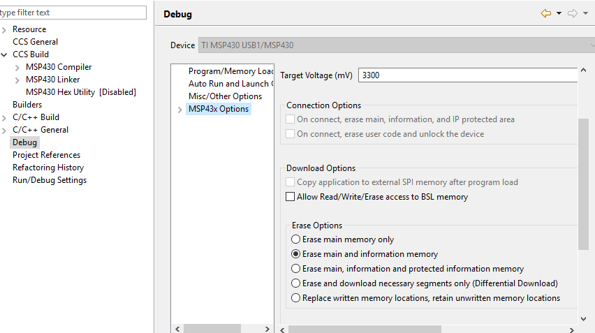
I've been happily(?) "debugging, loading & rectifying code" over & over for a while now & was busy doing the same yesterday when suddenly on one download cycle i got the message "Trouble Writing Memory Block at 0x1800 on Page 0 of Length 0x200: Could not erase device memory". Changing project settings didnt help, connecting disconnecting debuggers & board didnt help so i gave up leaving the board disconnected to power.

8 hrs later i come back & being the eternal optimist i retry & voila! it loads!

So now my questions are:

a) why did it happen in the 1st place that it could not load the program?.

b why did it work 8hrs later?

i'm developing a smart power meter using ccs6.1.3.00033 & msp-fet (no updates to either for the past month) on win10 64bit.

  • Moshe,
    Since nothing else changed, I'd have to guess that the either the capacitance of your SBW/JTAG channels changed, or the noise on VCC or some other channel changed.

    Are you using SBW or JTAG?
    Did you change the positioning of the board, wires, or items on your workbench?
    When the error first happened, had the board been connected to power for an extended amount of time?
  • Hi Cameron
    I'm using JTAG.
    As far as i can recall i hadnt touched anything....but it is a possibility. Previous messages regarding poor connections have been very explicit about not being able to communicate with the board.
    The board HAD been connected to power for a long time (days)...but it had been connected to power for extended periods previously.

    Is there anything to be learnt from the actual message? by that i mean, is it telling me "yes, i can communicate with the board, i can load the program in the mcu, but no, i just cannot write to the info area."....
    My first thought was that i had reached the erase limit but then realised that that was simply not possible.
    Then i thought, what about a change in the info area data or settings? but then recalled that neither had changed.
  • Moshe,
    It's difficult to say. It could be a permission issue (or some invalid logic state) that the power cycle fixed. It could also be the health of the power supply. e2e.ti.com/.../371557

    It could also be a CCS setting that was changed and reverted after you restarted your CCS session.

    Now that I reread your post and checked the memory section it errored on (INFO D), it seems mostly like either the permissions or settings thing. If it were another issue, I'd expect it to fail while writing main, unless the very first write is to INFO D for some reason.
  • Hi Cameron

    These are the download/debug settings that were always set...but what is interesting is that when i changed the erase options to "erase main memory only" i STILL got the same error message! And that really puzzled me.

  • Interesting. It sounds like you have something set to write there. Is this possible?
  • Hi Cameron

    As it is i AM using the infoD memory. I have an initialised structure in my application that utilises that space...but it hadnt changed in the last week...

    Also, a further issue arose which may or may not be connected....the enhanced UART A1 developed a couple of issues - namely it stopped recognising the receipt of NULL bytes AND started garbling transmitted bytes.

    I replaced my dev board with another and that all worked fine.

    So it would appear that something actually DID happen to the MSP the evening the memory block message appeared although the EXTENT of the issue wasn't entirely apparent.

    Thanks for your input!

    Best regards

  • Moshe,
    Can you post an oscilloscope capture of the uart transaction?

    Are you using DMA?
  • Hi Cameron

    I discovered that it wasnt reacting to null bytes when the logic analyser showed that the PC was transmitting them. And similarly, the analyser showed the garbled bytes the MSP was transmitting.

    No..i'm not using DMA..But i am tempted to do so (perhaps for the 2nd release).

    But i will re connect everything and hook it up to the scope and capture a transmission in the next day or two.

    kind regards

  • Sounds good, Moshe!
    Maybe try loading one of our UART examples to the suspect board and observe it's operation? This will help us confirm that it is an issue specific to that board.
  • Hi Cameron

    Sorry about the delay.

    The replacement board i was using packed up on the Tx side!...below is the waveform of both the Rx & Tx (Tx in yellow & Rx in blue) after it packed up & then with another board where the same comms produced correct signals..

    What has happened to the Tx side to produce such an output???...its almost like the Tx is mimicking the Rx.

    The correct signals came from the board I reconnected that was the cause of this thread & whose Rx side had previously packed up (see 2 msgs up)....but its now working perfectly (so being off mains for a few days resolved its issue)!! i have now kept it connected to mains and will see if it packs up again in a few days time.


  • moshe jacobson18 said:
    What has happened to the Tx side to produce such an output???...its almost like the Tx is mimicking the Rx.

    I would suspect an open circuit on the Tx such that the Tx trace is not being driven, and the scope picks up an low-level impulse when the Rx signal changes.

    Maybe there is a dry solder joint / cracked PCB trace such that the Tx connection is intermittent.

  • thank you Chester...there was!

    in fact, looking under the microscope, i could see the pin move when i nudged  it!!

  • Hi Cameron

    I'm working on new prototype board which has the problem of not picking up NULL bytes...it picks up the other bytes, just not NULL....why???

    The logic analyser picks it up correctly on the MCU Rx pin as  2h ABh CDh EFh 2Ah 20h 4h 5h 0h 5h 0h 24h 3h
    The captured waveform is as below.  Vmax is 4.08V Vmin is 0V Baud is 9600.

  • Hi Moshe,
    How are your UART registers setup?
    Is it setting any flags?
  • Hi Cameron

    This is the setup code and the interrupt code. Bear in mind that it works on other identical boards.
    And it is ONLY the NULL byte...transmission is fine (it sends the correct responses to packets that do not have the NULL byte).

    Oh, an one more thing, at some point the Rx & Tx pins may have been subjected to voltages of about 7V.


    void SetupRS232Port(void)
    {

      UCA1CTLW0 = 0; // this makes everything into the default state
      UCA1CTLW0 |= UCSWRST;   // Put state machine in reset
      UCA1CTLW0 |= UCSSEL1;   // use SMCLK
      UCA1CTLW0 |= UCRXEIE; //enable eroneous char intr..DO THIS ELSE WE MISS CRUCIAL BYTES
      UCA1BRW = ((uint16_t)0x68 );
      UCA1MCTLW = 0xd600 | 0x0020 | 0x0001;  
      UCA1CTLW0 &= ~UCSWRST;                  // Initialize USCI state machine...
      UCA1IE |= UCRXIE;                       // Enable USCI_A1 RX interrupt
      return;
    }

    // USCI_A1 interrupt service routine
    #pragma vector=USCI_A1_VECTOR
    __interrupt void USCI_A1_ISR(void)
    {
    uint8_t bb;

       switch (__even_in_range(UCA1IV, 10))
        {
          case USCI_UART_UCRXIFG:             // RXIFG
                bb = UCA1STATW & UCRXERR;// check if had an error (framing/overrun/parity)..reading resets the state which is important
                if(bb) // we had an error...so just recodr the fact for posterity at this time
                   ++rxErrs;
               rs232RxBuffer[rs232RxHead] = UCA1RXBUF; // auto clears the error status
              if(++rs232RxHead == MAXRXBUFFER)
                   rs232RxHead = 0;
              break;

           case USCI_UART_UCTXIFG:
               if(rs232TxHead != rs232TxTail)
                    UCA1TXBUF = rs232TxBuffer[rs232TxTail++];
               if(rs232TxTail == MAXTXBUFFER)
                   rs232TxTail = 0;
               if(rs232TxHead == rs232TxTail)
                   UCA1IE &= ~UCTXIE; // disable USCI_A1 TX interrupt
               break;      // TXIFG
          case USCI_NONE:
               break;                    
          case USCI_UART_UCSTTIFG:
               UCA1IFG &= ~UCSTTIFG;
               break;
          case USCI_UART_UCTXCPTIFG:
               UCA1IFG &= ~UCTXCPTIFG;
               break;  
          default:
               break;
          }
    }

    ......and elsewhere these few lines gets executed before the above

    #define P1DIR_INIT                                  (BIT7 | BIT5 | BIT3 | BIT2 | BIT1 |BIT0)
    #define P1SEL_INIT                                  (BIT5 | BIT4 | BIT3 | BIT2)
    #define P1OUT_INIT                                  (0)

      P1DIR = P1DIR_INIT;
      P1SEL = P1SEL_INIT;
      P1OUT = P1OUT_INIT;

    cheers
    moshe

  • Hi Moshe,

    So you said "new prototype" board, but there is no difference from the other boards? 

    7V could have caused damage that would be unpredictable in behavior.

**Attention** This is a public forum