This thread has been locked.

If you have a related question, please click the "Ask a related question" button in the top right corner. The newly created question will be automatically linked to this question.

MSP430FR6989: Erratum USCI41: Using SPI Slave Mode With DMA Channel

Part Number: MSP430FR6989

I have a question regarding one of the issues discussed in the errata data sheet for the MSP430FT6989:

USCI41 eUSCI Module Function UCBUSY bit of eUSCIA module stuck to 1 when device is in SPI mode. Description When eUSCIA is configured in SPI mode, and the last transfer bit changes from 0 to 1, the UCBUSY bit gets stuck to 1. This happens in all four combinations of Clock Phase and Clock Polarity options (UCAxCTLW0.UCCKPH & UCAxCTLW0.UCCKPL bits). There is no data loss or corruption. Because the USCBUSY bit is stuck to 1, the clock request stays enabled and adds additional current consumption in low power mode operation. Workaround Check on transmit or receive interrupt flag UCTXIFG/UCRXIFG instead of UCBUSY to know if the UCAxTXBUF buffer is empty or ready for the next complete character.

I've definitely identified that this is an issue - or perhaps have verified it - but if I'm using UCA0 as a SPI Slave; and I'm wanting to transfer a SPI packet when receiving; I'm a little unclear on the best method to determine if the port is still busy; especially when checking that the SPI packet has been transmitted.

Right now I'm seeing the packet being sent by as being misaligned from what I can tell by 2 bytes; meaning the first two bytes are from the previous data packet.

I suppose USCI45 isn't an issue in SPI Slave Mode, correct?

USCI45 eUSCI Module Function Unexpected SPI clock stretching possible Description In rare cases, during SPI communication, the clock high phase of the first data bit may be stretched significantly. The SPI operation completes as expected with no data loss. This issue only occurs when the USCI SPI module clock (UCxCLK) is asynchronous to the system clock (MCLK). Workaround Ensure that the USCI SPI module clock (UCxCLK) and the CPU clock (MCLK) are synchronous to each other.

This is fairly straight forward; but I was wondering about the best way to determine when the transmission was still taking place since this is a slave - something like this won't work due to the errata:

while ( EUSCI_A_SPI_isBusy(EUSCI_A0_BASE)== EUSCI_A_SPI_BUSY ) //SPI still sending data? - errata
;

I'm also doing this with DMA - 2 channels - 1 for receive and one for transmit.

For this errata:

DMA7 DMA Module Function DMA request may cause the loss of interrupts Description If a DMA request starts executing during the time when a module register containing an interrupt flags is accessed with a read-modify-write instruction, a newly arriving interrupt from the same module can get lost. An interrupt flag set prior to DMA execution would not be affected and remain set. Workaround 1. Use a read of Interrupt Vector registers to clear interrupt flags and do not use readmodify-write instruction. OR 2. Disable all DMA channels during read-modify-write instruction of specific module registers containing interrupts flags while these interrupts are activated.

Is it OK to execute this:

DMA_disableTransferDuringReadModifyWrite();
DMACTL0 |= DMARMWDIS;  // and/or?
DMACTL1 |= DMARMWDIS;  // and/or ?

Thanks,
John W.

  • Hello John,

    As far as USCI41 is concerned, you would just have to trigger a read of RXBUFF once UCRXIFG is set, and you can fill TXBUFF once UCTXIFG is set. To get around DMA7, you would just need to disable DMA before you were to manually clear the UCTX/RXIFGs. The auto-clear of these flags when going into their associated interrupt is not affected for its a read only instruction.

    In accordance to your issue of misaligned packets, are you losing any SPI data or double transmitting any data? What kind of processing are you doing on the data before sending it back to the master?
  • Hello Jace,

    Thanks for the reply.

    The received packet seems to be working fine; I'm using DMA for that as well.

    The packet to be transmitted back is assembled between SPI commands and is ready to go on the next SPI packet received.

    The data isn't being overwritten; but seems to be 'wrapped' by being delayed or off by two bytes as shown in the images above.
    The data isn't being transmitted more than once either - I've verified that as well.

    When reviewing the errata and since I need DMA in this case due to performance requirements; I was unclear on how to determine when the return packet was actually finished being transmitted. The packet size is relatively small right now; which makes me wonder a little more about the packet misalignment.

    I am using the FRAM obviously on the '6989 and have had to enable 2 wait states for that; didn't think that was an issue either but thought I should mention it. We have both the 32.768 kHz XTAL plus 24-MHz HF XTALS on this design and I am using both. I'm running MCLK at 24MHz and SMCLK at MCLK/2 = 12MHz.

    I must admit I was a little surprised to see this errata since on other 430's I've used this DMA driver with SPI and it worked fine; but the UCBUSY bit worked properly on those processors.

    while ( EUSCI_A_SPI_isBusy(EUSCI_A0_BASE)== EUSCI_A_SPI_BUSY ) //SPI still sending data? - errata
    ;

    was used in the TX part of the DMA IRQ and I was still a little unclear on how to do something equivalent based on the errata.

    When I initially saw this issue I thought I was having a lib issue since I'm using memcpy, memset, etc. on a unint32_t and it looked like a Big Endian/Little Endian issue at first glance; but that isn't really an issue here.

    The other thing I thought was a little unclear is having to do an initial write to UCA0TXBUF or the DMA IRQ seems to never XMIT a packet; I've seen quite a bit of discussion on that issue in these forums. I thought that was an issue also but the packet will realign on the received packet vs. the xmitted pkt.

    Thanks,
    John W.
  • Hello John,

    Since you are not getting any double transmission or overwriting of packets, then we can assume that you are actually getting the correct data to the USCI and that doing this with the DMA is fine. If these errata were affecting your application, I would expect a double write, overwrite, or a transmission of all F's or 0's during the transactions. I assume here you are using some kind of buffer to store the data you want to send. I would try to capture on the logic analyzer when the first transactions take place to see if the first byte sent by the MSP430 is offset by more than one. This would mean that the processing of the first transaction takes too long before the second byte comes in. As a slave device, I expect the transactions to be off by one alignment for the slave device will not transmit until it is written to and you don't know what you want to send on the first received byte. For example, if you send the MSP430 6 bytes, and expect the 6 bytes to be echoed back, you need a total of 7 transactions, with the 7th byte being a dummy write byte transmitted by the master. If you have a dummy write by the master, then every transaction should line up properly. I'm not sure if this is what you are doing, and if this initial alignment is being taken into account or not.
  • Hello Jace,

    What I'm doing in this protocol is sending the initial packet - and then on the subsequent packet are sending the answers.  So:

    for packet n - packet n+1 contains the response - and to get the last response a dummy packet has to be sent to get the last packet.

    I've seemed to have corrected the packet alignment issue; but I'm not so sure now I'm not overwriting data - please see the attached images.

    I've tried about everything; including semaphore protecting this data packet - and no matter what I do; I'm seeing the attached.  Since I also only seem to have one functioning breakpoint on this processor; I'm not able to do a lot as far as figuring out the issue in the debugger; from what I can tell in the debugger right now; the packet looks fine.  Anytime I use the debugger obviously; it affects the SPI bus timing so I have to take that into account with the results.

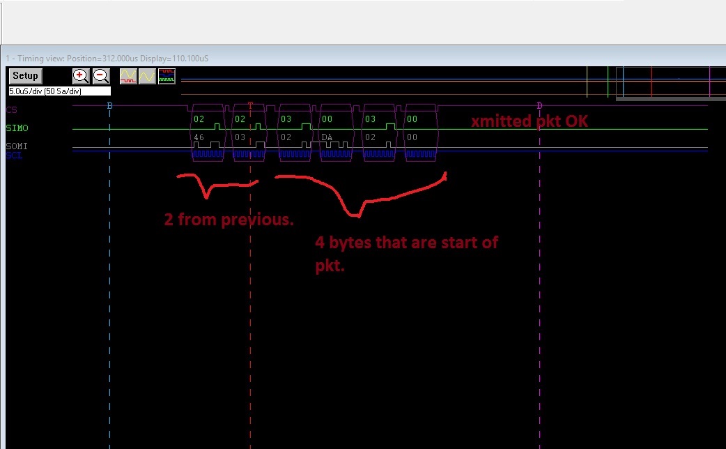
    Figure 1:  Aligned Packet Response - 0xFF - packet init chars - 0x89 is part of response - 0x02 - STX, 0x03 ETX

    (top packet is n+1, bottom packet is response to packet n)

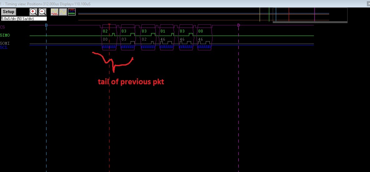
    Figure 2:  Last 'part' of last packet - 0x00's are part of response, 0xFF is part of init packet, 0x02 STX, 0x03 ETX

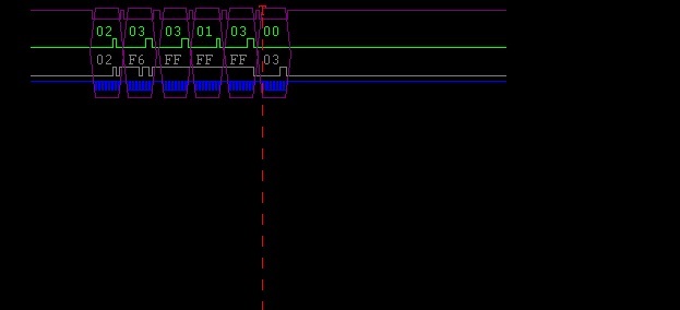
    Figure 3:  'Count' is getting ready to go beyond 8 bits; 0xF6 is part of data packet, 0x02 STX, 0x03 ETX, 0xFF part of init pkt.

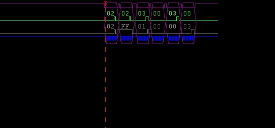
    Figure 4:  Counter has 'rolled' now - 0xFF part of old init pkt - 0x01 is 2nd byte of count now; 0x02 is STX, 0x03 is ETX.

    So, for the above, the count as of the sample in Figure 4 is 0x1F6.

    When I first saw this problem I thought it was a lib issue with big/little endian as the 430 is BE and the ARM processor I am using is LE; but something apparently was/is clobbering the packet.

    Between packet responses the pkt gets set to all 0xFF's.  

    From these results; it almost seems that there's a buffer someplace that's storing part of the packet data.  In the code I have; I went to the length of semaphore controlling the DMA transmission and reception and also semaphore controlling when the data packet could be written and read - and I'm still getting the above results.

    Thanks,
    John W.

  • Hello John,

    The best way to start debugging this is to isolate the issue by simplifying the trouble area. A few ideas come to mind.

    • Is it possible to strip down your code base to just the reception and transmission of these data packet? This would isolate issue to DMA transfers, USCI TX/RX and Buffer management.
    • For the data packets that are being sent from the MSP, can these be replaced by dummy data of a known pattern? Something along the lines of increasing values with two different packet sets? This would help determine if you are getting double or missed values in the sequence.

  • Hello JH,

    The actual solution is having the following errata to be fixed:

    USCI41 eUSCI Module Function UCBUSY bit of eUSCIA module stuck to 1 when device is in SPI mode. Description When eUSCIA is configured in SPI mode, and the last transfer bit changes from 0 to 1, the UCBUSY bit gets stuck to 1. This happens in all four combinations of Clock Phase and Clock Polarity options (UCAxCTLW0.UCCKPH & UCAxCTLW0.UCCKPL bits). There is no data loss or corruption. Because the USCBUSY bit is stuck to 1, the clock request stays enabled and adds additional current consumption in low power mode operation. Workaround Check on transmit or receive interrupt flag UCTXIFG/UCRXIFG instead of UCBUSY to know if the UCAxTXBUF buffer is empty or ready for the next complete character.

    Can you tell me when TI plans to have that fixed?
    I have previous SPI/DMA drivers that rely on:

    while ( EUSCI_A_SPI_isBusy(EUSCI_A0_BASE)== EUSCI_A_SPI_BUSY ) //SPI still sending data? - errata
    ;

    That work just fine; as stated in the OP.

    Thanks,
    John W.
  • JH/TI,

    Also - there used to be a bug using the DMA code and having to make sure your data pointers were 20 bits vs. 16-bits.

    I don't think that is an issue here but I am using the large data model; and I noticed the routines in the lib are using 16-bit pointers.

    Regards,
    John W.
  • Hello John,

    As far as fixing errata when it comes to a device, when a new device revision is planned, each erratum is looked at to see if it is feasible to be fixed in the new revision. These decisions are made on a case by case basis at the planning stage of a new device revision. I cannot say when a new revision of these devices will be done and if a fix for this particular errata would be included or not in that revision.

    For your DMA code, the 16-bit pointers will be fine as long as your lib never crosses into the higher range of memory for your Source/Destination Addresses. Otherwise, they will need to be changed to 20-bit values.

**Attention** This is a public forum