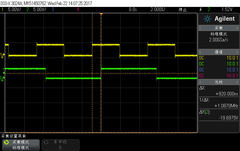
Hi all,
I'm now working on a sw SPI code(slaver) using FR2311, MCLK = 16MHz, and I find the CPU cost nearly 1us to response the ISR(TB1.1 P2.0 Capture).
It sounds a little long....
Is it normal ? Hope someone 's help.
Thanks...
#include <msp430fr2311.h>

void main( void )
{
  // Stop watchdog timer to prevent time out reset
  WDTCTL = WDTPW + WDTHOLD;

  FRCTL0 = FRCTLPW | NWAITS_1;

  __bis_SR_register(SCG0);                           // disable FLL
  CSCTL3 |= SELREF__REFOCLK;                         // Set REFO as FLL reference source
  CSCTL0 = 0;                                        // clear DCO and MOD registers
  CSCTL1 &= ~(DCORSEL_7);                            // Clear DCO frequency select bits first
  CSCTL1 |= DCORSEL_5;                               // Set DCO = 16MHz
  CSCTL2 = FLLD_0 + 487;                             // DCOCLKDIV = 16MHz
  __delay_cycles(3);
  __bic_SR_register(SCG0);                           // enable FLL
  while(CSCTL7 & (FLLUNLOCK0 | FLLUNLOCK1));         // FLL locked

  CSCTL4 = SELMS__DCOCLKDIV | SELA__REFOCLK;        // set default REFO(~32768Hz) as ACLK source, ACLK = 32768Hz
  // default DCOCLKDIV as MCLK and SMCLK source

  P1DIR |= BIT0;                                   //P1.0 output

  P2DIR &= ~BIT0;		                        //P2.0 as caputure port
  P2SEL0 |= BIT0;

  PM5CTL0 &= ~LOCKLPM5;                              // Disable the GPIO power-on default high-impedance mode
  // to activate previously configured port settings

  TB1CCTL1 |= CM_1 | CCIS_0 | CCIE | CAP | SCS;
  TB1CTL |= TBSSEL_2 | MC_2 | TBCLR ;              // Use SMCLK as clock source, clear TB0R

  __bis_SR_register(LPM0_bits | GIE);
  __no_operation();
}

#pragma vector = TIMER1_B1_VECTOR
__interrupt void TIMER1_B1_ISR(void)
{
  P1OUT ^= BIT0;
  TB1CCTL1&= ~CCIFG;
}


