This thread has been locked.

If you have a related question, please click the "Ask a related question" button in the top right corner. The newly created question will be automatically linked to this question.

MSP430F5638: how to control or know 2K RAM for USB, how to allocated and used

Part Number: MSP430F5638
Other Parts Discussed in Thread: MSP-FET

Hi

My MSP430F5638 USB is working, but once a long time, the USB COM port does not make a connection. or user (like PC) requests MSP430F5638 can not get.  The PC and device recognize the USB COM port, an dit connected with PC sounds and LED on the MSP side blinking. I don't why the request not get pass in to the MSP,  The experts told me to see the 2K RAM used by the USB.  it may not able to allocated memory space, USB needs it. but I don't know where to see or debug the 2K RAM USB used. does anyone know how? 

  • Hi Louis,

    Are you asking how to view what's in the RAM over USB using an IDE (e.g. CCS, IAR, etc.) or are you asking how the memory is allocated?

    Regards,

    James

    MSP Customer Applications
  • Yea,
    I use IAR as development tool.
    case 1: During JTAG debug, connect it from IAR, the USB port works good, keep the communication with PC at second day plug in USB, during overnight device runs on battery power.

    case 2: But if the JTAG connection is off, device is battery powered, and firmware runs over night, the device USB port does not communicate with PC any more at second day morning plug in USB.

    I need solve this in order to make product usable. Do you have any suggestions how to debug it?

    What I can do: I can make the LED light on/off or toggle the LED and internally log events during run time, and access event from other UART ports. not able to debug, if does the device get reset, than communication start work with PC through the USB again. I think it is very difficult not reset device and debug in section again. The run firmware is same as the JTAG debug firmware.
  • Hi James,
    I am interested to view what's in the RAM over USB using from IAR, to see how the 2K USB memory keep it only for USB using, and to allocate 2K memory during the running.
  • Hi Louis,

    When you click the "Download and Debug" button in IAR, you can then halt the debugger to view the contents of the RAM. While halted in IAR, you can go to "View" -> "Memory" and then in the Memory window that pops up, change the drop-down box from "Memory" to "RAM" to view the RAM.

    I think I'm starting to understand your issue. Are you saying that the device USB port only works when you've connected to an active debug session? Typically, when there's an active JTAG connection, the timing of the device changes. Also, perhaps the debug session is preventing your device from going to sleep into a low power mode (LPM). Thus, it keeps the USB communication with the PC active. However, if you enter into a LPM that disables clocks/modules that affect the USB module, I can see where this would prevent the communication when you're not debugging.

    I'm assuming that you have two USB connections to the device: one for debugging over JTAG with the MSP-FET, one for the device USB interface (e.g. D+, D-).

    Regards,

    James

    MSP Customer Applications
  • Hi James,

    The device with USB and device is powered from battery and USB, At initial device turn the power on, plug and unplug USB, the USB communication works on all the devices.  but if unplug USB, leave battery powered devices, run log time, some of the devices could run over night, some of them could run over weekend.  others can run multiple days, after the multiple days or long time runs without USB connected, plug in (connect to) the USB again, the USB communication does not work. The USB to PC connection can be on always.  it can see from PC device manager or from Firmware lights up device's LED.    


    From what you suggested, it is when USB to PC connection is on, do not go into LPM, the USB has power line, device no need in LPM anymore.  

    From USB_connectionState() can tell the connection is on or off. only device go into LPM is when device has no USB connection.   In my test case, during multiple day run on the battery, device go into LPM3 to save battery power, When USB connected or USB_connectionState() return ST_ENUM_ACTIVE, not go into LPM anymore, did I understand you right?   The yesterday firmware tests, the device firmware go into LPM0  I have 7 device tested, none of them had failure yet.  do you think I should remove PLM0 when USB_connectionState() returns ST_ENUM_ACTIVE?  USB_connectionState() returns ST_ENUM_IN_PROGRESS, it will not in LPM.  Could you please confirm what I did right or wrong.  please advice me with more your suggestions.

    Louis 

  • Hi Louis,

    This makes sense. According to Section 42.2 in the User's Guide, the USB module on the MSP430F5638 supports active operation during power modes Active Mode (AM), LPM0, and LPM1 only. This is the reason why you didn't have any failures when you used LPM0 rather than LPM3.

    Thus, I'd suggest that you continue using LPM0. If you must use LPM3 to save power consumption, I'd recommend waking the device up periodically to check if there's a USB connection. Obviously, this won't allow you to detect a USB connection immediately and there will be some delay. I'm not sure if this is important or not for your application.

    Hopefully this helps!

    Regards,

    James

    MSP Customer Applications

  • Hi Louis,

    I just wanted to let you know that I'm also working with Paul on this issue in the thread below. Hopefully we can resolve this issue for you both!

    Regards,

    James

    MSP Customer Applications

  • Hi James,

    There are three application cases.

    1. The USB is not connected, device run on battery, Firmware is in LPM3, but USB port hardware is ready to be used or connected. 

    2. detect the USB is connected, but ENUM is in process, device run on USB power and battery is connected too. Firmware is in AM

    3. detect the USB is connected. ENUM is actived, device run on USB power and battery is connected too, Firmware is in LPM0 or AM

    during the weekend tests, the most time, devices is in case 1 in my 4 units, Monday morning, 4 devices, one at time will be in case 2 and 3, my 4 units all works.  but my co-working has 3 units, two did not work and 1 works, he used same firmware image

    my questions is in case 1 the device should be in LPM0 or LPM3.  From what your suggestion on last Friday.  if device plan to use USB, the device should be in LPM0 or LPM1, is that correct?

    if it is right, this is kind explain why some of units work, other units do not work, also if the unit works, it always work, if it does not work, no matter how many time plug and unplug USB, the USB communication will not work.  The USB does not work case, it is hard to explain from what I know.  

    let me know what is your suggestion?  in case 1 device should keep in LPM3 or in LPM0 / LPM1 to later keep USB connection works again, when user plug in USB again. 

    Louis

  • Hi James,
    From Section 42.2 in the User's Guide, NOTE: The USB module only supports active operation during power modes AM through LPM1.

    The USB module, it does not matter USB port is connected or unconnected.

    If firmware/user plan to use USB module, the MSP430f5638 can not be in LPM2 above, is this right understanding?

    Louis
  • Hi Louis,
    If you have not solved your issue, maybe the items listed in section 6.4 and 6.5 of the Programmers_Guide_MSP430_USB_API.pdf might help. This guide is part of the MSP430USBDevelopersPackage. Since your device is constantly powered by the battery and your application is always running, you might need to update your application to trigger an event when you re-connect to the host via USB.

    Also if the above suggestion does not work, maybe you can also set the device's remote wake up capabilty. See section 6.9. If this capability is set in the device then you will also have to enable this capability on the Windows side.

    Finally, can you also verify that the settings in descriptors.h file for USB_SUPPORT_SELF_POWERED is also set properly.

    Regards,
    Arthi Bhat
  • One more thing.  Here is a link to an application note that uses battery and switches between USB and battery.   

    www.ti.com/lit/pdf/slaa529

    Regards,

    Arthi

  • Hi Arthi Bhat,
    This project does not have program resource to do USB API level driver. the only two or three functions interface with device firmware are USBCDC_handleDataReceived(), cdcSendDataInBackground() and USB_connectionState(). anything more, it could cause more issues. also the USB driver is 2.21.0.39.

    the system is basically working. the issues is the USB communication does not work on all devices, all the time, example 10 devices, after overnights running, some of them, the USB communication works, maybe 70% of devices, and 30% USB do not communicate after over night running example the 8 units tested over the past weekend, 6 work and 2 do not work. if connect one more device, it may not work or may work. so the issues is the changes to make 100% all work. confident to send device to user to use. if you tell me to look the API again, that may go back to far.

    James told me the LPM0 and LPM1 looks is the fixed direction. all I would like to confirm with him. but some how , you make a suggestion look the API to change that, I do n't have time to do that and resource to do that. you need talk to James get some other plan to fix the issues.

    Louis
  • Hi Arthi Bhat,
    Some how you made the reply not show any more.
    Louis
  • Louis,

    You need to click the back arrow at the bottom to view replies on the previous page. This happens when there are many replies.

    Regards,

    James

    MSP Customer Applications

  • We have not yet solved the problem.  We will check out your suggestions.

    Also, Slau280P has a note in section 42.2 that states "The USB Module only supports active operation during power modes AM through LPM1".  Is this to say that we need to be in LPM1 or higher BEFORE the USB cable is plugged-in?  Or does it mean we must switch to a higher mode once USB is detected?

    Thank you.

    Regards,

    Paul

  • Hi Paul,

    It means that you need to switch to a higher mode AFTER the USB is detected. In our code examples, this is typically done immediately when switching to the ST_ENUM_ACTIVE case in the USB_getConnectionState() state machine.

    while(1)
    {
         switch(USB_getConnectionState())
         {
              case ST_ENUM_ACTIVE:
                   __bis_SR_register(LPM0_bits + GIE); // Enter LPM0
                   function_as_USB_active();
                   break;
              case ST_PHYS_DISCONNECTED:
              case ST_ENUM_SUSPENDED:
              case ST_PHYS_CONNECTED_NOENUM_SUSP:
                   __bis_SR_register(LPM3_bits + GIE); // Enter LPM3
                   function_as_USB_inactive();
                   break;
              default:;
         }
    }

    I see that Louis mentioned above that 70% of the boards were passing while 30% of them were failing. This behavior makes me suspect that there's a hardware issue between the boards. If there was a software issue, I would expect all the boards to either pass or fail. Also, during the failures that you're observing, you are seeing the device enumerated in Device Manager on the PC but it won't communicate, correct? It'd be helpful to know which case statement above that it's ending up in.

    With this in mind, what's sourcing XT2 for the USB PLL? Section 11.2.3 in the MSP430 USB API Programmer's Guide talks about several important requirements for the PLL reference. If a crystal is being used for XT2, Section 11.2.5 talks about the importance of the load capacitors. Make sure it meets the requirements specified in the datasheet.

    Section 12.2.1 has some good things to check that will help us narrow down this issue.

    • Check the hardware for anything that's missing. Refer to the schematic in the Starting a USB Design Using MSP430™ MCUs app note.
    • When a failure occurs, check that the clock frequency is available on XT2. Do NOT probe the oscillator directly but send XT2 to the SMCLK or ACLK output pins and probe there.
    • Check for oscillator faults.
    • Make sure interrupts are getting handled properly. General interrupts could be getting disabled somewhere.

    Regards,

    James

    MSP Customer Applications

  • Hi James,

    We are switching from LPM 3 to LPM 0 upon detection of USB and switching back to LPM 3 on completion of USB comm.

    When the boards do not communicate, the PC always recognizes the port.  We get the device connect sound from the computer and the correct port shows up in device manager.

    The 30% figure from Louis was for boards that were flashed and tested immediately.  When re-flashed, they all worked.

    Question 1: If the PC always detects the port, does this mean that the USB oscillator is always starting?

    Question 2: We are using MSP430USBDevleopersPackage_3_20_00.  We know that there is a more recent version but we are concerned that upgrading will cause other problems.  Could this be causing our problem?

    Thank you.

    Paul


  • Hi Paul,

    Thanks for the additional details. The behavior for the 30% failure is very strange. I'm not sure why simply re-flashing the device would help unless the data is somehow getting corrupted during programming.

    How are you programming the device? Which debugger are you using (e.g MSP-FET)? Which interface are you using (e.g. BSL, 4-wire JTAG, 2-wire SBW)? Can you please provide detailed steps including programming and testing?

    For example, let's say you program the device over 2-wire SBW, and the device is powered by the MSP-FET. After programming, let's say you disconnect the MSP-FET from the board, and the battery powers up the board. Then, let's say you plug in the board via USB to the PC, it gets enumerated, gets powered by VBUS, and you can pass data between the board and PC. Then, let's say you wait 3 days with the board operating on battery power only with no power-off events occurring. Then, you reconnect the device to the PC via USB, the board is now powered by the VBUS, and the device gets enumerated on the PC, but data can't be received.

    Some additional questions:

    • When the board gets connected to the PC via USB (not the JTAG interface), is the battery power turned off at any time?
    • Are you keeping the JTAG connection active when you're performing this testing over several days?
    • Can you send us a screenshot of your Device Manager? Ideally, it will show two COM ports (one for the JTAG connection and the USB CDC connection).
    • Has anything changed between an older design where this code was working to this (assumed) newer design?

    Paul Mayer said:
    Question 1: If the PC always detects the port, does this mean that the USB oscillator is always starting?

    That's correct. When enumeration has occurred and the PLL/oscillator is working at the right frequency, the device can be seen in Device Manager.

    Paul Mayer said:
    Question 2: We are using MSP430USBDevleopersPackage_3_20_00.  We know that there is a more recent version but we are concerned that upgrading will cause other problems.  Could this be causing our problem?

    This shouldn't be causing the issue.

    Finally, I'd recommend that you not keep an active debug session while you're testing this issue. Instead, put code that turns on LEDs in the various states to figure out which state your code ends up after the device enumerates but won't send data.

    Thanks for your patience while we try to nail down the issue.

    Regards,

    James

    MSP Customer Applications

  • Hi James,

    We have two ways to program the board: JTAG and our own GUI through a com port (USB, 485, 232).

    We use the MSP-FET tool when programming through JTAG and use either IAR tools or the MSP flasher software.

    We have let the unit run with the debugger plugged in and tested with USB using a second computer.  This never fails.

    Here are the detailed steps:

    1. Use JTAG and software to flash firmware into MSP430. Unit powered by JTAG only

    2. Remove flasher.  Unit powers down.

    3.  Connect external power (battery).  Unit powers up.

    4. Open GUI.  Connect USB.  Gui detects USB and identifies port.  Using driop-down menu on GUI, select port.

    5.  Communication established.  Use GUI to set operating parameters, units, time etc.

    6. Remove USB cable from computer.  Unit now running on battery only.  Close GUI

    7. Wait 2-3 days.  Open GUI.  Connect USB cable. Device gets enumerated. PC polls unit.  No response.

    The battery remains on all of the time.  A power cycle always alllows communication to resume.

    The JTAG is not active when running over several days.

    We did one test with and active debug session over several days and there was no failure.

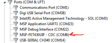
    The screenshot of the device manager ports appears below:

    Thank you.

    Paul

  • Hi Paul,
    So are you saying that you are having problems with JTAG communication after several days? What port is your GUI communicating on? If it is COM8 as the arrow shows, then that communication is happening on JTAG. The USB stack 3_20_00 is code for peripheral side USB. Updating and changing USB stack 3_20_00 to fix JTAG communication issues will not work. According to device manager, it looks like peripheral side CDC device is enumerated as shown by COM14. Can your GUI communicate on that port with the device?


    Regards,
    Arthi
  • Hi Arthi,

    Our problem is that with no JTAG, no USB, no communication, the unit running on battery power only, after a few days plugging-in USB does not communicate even though enumeration always occurs.

    We have no issues with JTAG. Only USB.

    Thank you.

    Paul
  • Hi Paul,

    We are not sure why you are seeing incosistent results with your devices where in some cases the devices work and in others they don't until you re-flash the device.

    The link that I sent in a previous post points to an application note from which you can download code that shows how to make a battery powered + USB powered device work in each USB state.  It might be worth looking at and adapt it to your application.  

    Since you are seeing enumeration but no communication  from device to GUI, I would assume that the device is getting placed in some other state other than active. To figure out where exactly the USB state is at, maybe a flashing LED can be implemented with different flashing rates in each of the USB state.   Once the stuck state is determined maybe you can implement something like the following code to get it un-stuck:


    case ST_USB_CONNECTED_NO_ENUM:
                	// We switch on USB and connect to the BUS
                	if (USB_enable() == kUSB_succeed){
                	    USB_reset();
                	    USB_connect();           //generate rising edge on DP -> the host enumerates our device as full speed device
                	}
                	enum_in_prog = TRUE;
                	enable_sleep = FALSE;
                    break;

    Regards,

    Arthi

**Attention** This is a public forum