This thread has been locked.

If you have a related question, please click the "Ask a related question" button in the top right corner. The newly created question will be automatically linked to this question.

MSP-EXP430F5529LP: Using ADC12 and ACS712 Current Sensor

Part Number: MSP-EXP430F5529LP
Other Parts Discussed in Thread: MSP430F5529,

Hello Forums,

I am trying to get the MSP430F5529 on the LaunchPad mentioned (MSP-EXP430F5529LP) to read the voltage that is output from a 5A ACS712 current sensor. The sensor is power using the 5V and GND pins on the LaunchPad (in the 40-pin Booster Pack section). The sensor output can reach close to 5V when 5A of current flows through it, so I used a potential divider (with 3k resistors) at the sensor output to half the output voltage. The output of the divider is fed to P6.0 on the LaunchPad.

The relevant code I wrote for this is:

//  Function name: ADC_Init
//  Purpose: Initializes and configures MSP430 ADC for conversion of ACS712 voltage reading to current
//  Inputs: none
//  Returns: none

void ADC_Init(void){

    REFCTL0 &= ~REFMSTR;                    //Set voltage reference control to ADC_12 registers

    //ADC Control Registers Setup
    ADC12CTL0 = ADC12SHT0_9|ADC12REFON|ADC12REF2_5V|ADC12ON;        // Sample and hold time, adc reference generator on and set to 2.5V, adc on
    ADC12CTL1 = ADC12SHP;                                           // SAMPCON signal source
    ADC12CTL2 = ADC12RES_2;                                         // 12-bit resolution

    ADC12MCTL0 = ADC12SREF_1 + ADC12INCH_0;                         // REF: Vref+ to MCU GND; Port 6 pin 0
    P6DIR = 0x00;               // P6.0 as input
    P6SEL |= 0x02;              // P6.0 to be used by ADC
    ADC12CTL0 &= ~ADC12SC;      // Clear 'Start Conversion' bit, to ensure conversion not started
    ADC12CTL0 |= ADC12ENC;

}

//  Function name: Get_ACS712_Value
//  Purpose: Reads ACS 712 current sensor output voltage via ADC, then convert voltage to current
//  Inputs: none
//  Returns: Current value from ACS 712 Sensor

void Get_ACS712_Value(void){

    ADC12CTL0 |= ADC12SC;                               //Start ADC conv.
    while (ADC12CTL1 & ADC12BUSY){                      // Poll busy bit waiting for conversion to complete
        __no_operation();
    }

    unsigned int acs_voltage = ADC12MEM0 & 0x0FFF;                      // keep only low 12 bits

    float acs_volt2 = 2 * ( (float) acs_voltage) * (2.5 / 4095.0);

    bat_states.current = (acs_volt2 - 2.525) / 0.185;    // x10 for 5V range on acs_712; x20 for 2.5V range on acs_712
}

Using this setup, and the code above, I am not getting the correct value. The value I am getting is -13.3A, which is way off, since it is out of the range of the sensor. Removing the sensor output from P6.0 gives a value of -13.6A. I am not sure where this offset is coming from, as it does not appear to be a calculation error.

 I can verify that current sensor/potential divider setup works, and outputs approximately 1.25V for 0A through it, as expected. Connecting the sensor output to P6.0 does seem to drop the sensor output voltage to a very low value, around 0.03V.

Does anyone know what may be happening here?

Am I attempting to draw too much current from the LaunchPad, or is it a calculation error?

I did not configure P6.0 to use a pull-down resistor, so I am not sure what is causing this.

Regards

  • Hi Raheem!

    Raheem Hall said:
    Connecting the sensor output to P6.0 does seem to drop the sensor output voltage to a very low value, around 0.03V.

    Maybe your pin is configured as output with low level?

    Raheem Hall said:
    P6SEL |= 0x02; // P6.0 to be used by ADC

    This is the wrong P6SEL bit - for P1.0 you need 0x01.

    Raheem Hall said:
    Removing the sensor output from P6.0 gives a value of -13.6A.

    Let's say the pin is at GND level, then acs_volt2 results in 0.0 and bat_states.current will be [(0.0 - 2.525) / 0.185] = -13.65 <- this is your result.

    Dennis

  • Hello Dennis.

    Thank you for your reply.

    I will change P6SEL to 0x01, and see what happens soon.

    Doesn't, the line before that error, P6DIR = 0x00, set pin 6.0 as an input? If so, how can the pin be at ground level?

    Regards

  • Raheem Hall said:
    Doesn't, the line before that error, P6DIR = 0x00, set pin 6.0 as an input?

    Yes, that's right.

    Raheem Hall said:
    If so, how can the pin be at ground level?

    Good question ;)

  • Maybe you are sampling too fast / your S&H time is too little for the impedance of the voltage divider? What happens if you pull P6.0 to DVcc - does the ADC result change to FFFh? Try to extend the S&H hold time. Additionally you could add a small capacitor from the center of the divider to GND.
  • Hello Dennis,

    I found the problem (a basic problem I overlooked, really). After defining those functions (in particular the ADC_Init() function), I was setting all ports to a low output. I simply switched these around, and everything works well now.

    The only issue now is, the value fluctuates significantly, between 0.1 A and 0.3 A. I added a capacitor in parallel with the second resistor to ground. The value still fluctuates, over a smaller range of -0.028 A and 0.078 A. 

    Do you have any tips to fix this? Should I use a larger capacitor, or can this be somewhat fixed in code?

    Regards

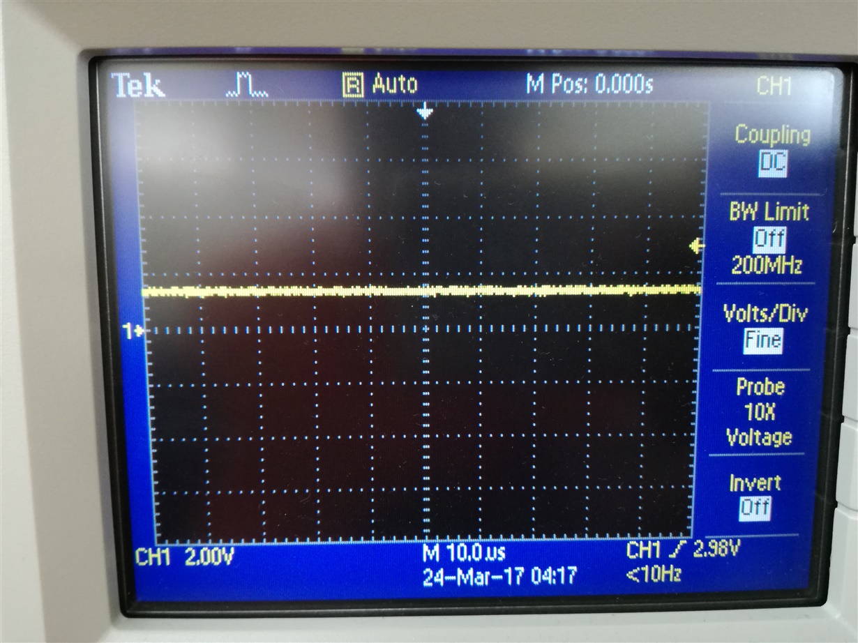
  • What does your scope say?
  • Raheem Hall said:
    I added a capacitor in parallel with the second resistor to ground.

    Which value did you choose?

  • Hello Keith

    This is the reading from the scope

    As you can see, it looks relatively constant. This is with the 10uF capacitor.

    Regards

  • I am using a 10uF electrolytic capacitor.

    Regards
  • My eye says it ranges from 1.2 to 1.6 V, or a variation of 28%.

    Software can certainly help. You can average several values, or maintain a running average.
  • Raheem Hall said:
    I am using a 10uF electrolytic capacitor.

    OK, that is quite large - of course this value should smooth your signal significantly, but depending on your application, it also slows down the step response.

    Is you fluctuation up and down or is your result slowly going down only?

  • Some troubleshooting steps:

    Do you get a good reading when you use your scope and calculate by hand?

    Given what the scope measures, does the ADC count reflect that?

    If the count is not correct, does it appear that the reference voltage is off? If you measure it a bunch of times do some of the values appear correct?

    If the count is correct separate all the math steps into single operations, i.e change x = c + a*b into x = c, y = a*b, x = x+c
    Do all of those make sense?
  • It is fluctuating up and down; the calculated value ranges from 0.09A to 0.45 A rarely, but most stays around 0.27A to 0.37A.

  • Based on the scope photo earlier, I can agree that the voltage output from the sensor ranges from 1.2V to 1.6V. This corresponds to an ADC value of about 1966 to 2622. The average ADC count falls within this range, and its value is about 2105 - 2129. Remember the mid-point of the ADC range should be about 2048.

    Using these values, I hand calculated what values I should have gotten, I can verify that what I calculated agrees with what the program calculates.

    I believe this puts the problem on the sensing circuit/ADC side. I did not check the reference voltage.

    Regards

**Attention** This is a public forum