This thread has been locked.

If you have a related question, please click the "Ask a related question" button in the top right corner. The newly created question will be automatically linked to this question.

MSP432P401R: XDS110 can't load new code into MCU after a mistake. Advice needed.

Part Number: MSP432P401R

We were trying to measure how much power our device consumes which uses the MSP432P401R. In order to measure that We first turned off all our additional devices we had attached(by putting them into sleep) and we measured a high consumption. A lot higher than we estimated. After that, we thought that maybe undeclared pins were doing this so we declared all unused pins to be outputs and 0. And here is the problem. I did not read in advance the datasheet part where it was told what to do with certain unused pins. So we declared the J-pins to be output 0 and we put the MCU into low power mode 4.5.

We are using XDS110 and we are programming our device from the upper part of the red MSP432 launchpad. If needed I will attach a picture. Basically, we are using the programmer of the launchpad to load our code into our device.

After I put this code into the MCU I am not able to put any new code into it. I always get his error:

"Error connecting to the target:
(Error -1170 @ 0x0)
Unable to access the DAP. Reset the device, and retry the operation. If error persists, confirm configuration, power-cycle the board, and/or try more reliable JTAG settings (e.g. lower TCLK).
(Emulation package 6.0.628.1)

No connection possible. This could be caused by the device having gone to low power mode and disabling JTAG PINs.
You have the option to either toggle reset or try to use SWD instead."

And I have the option to Toggle RST and I did that but nothing happened. We checked with an oscilloscope if the RST pin on the MCU works and it works, it shows that the toggle was done, but we still get the same error. We don't know what SWD is, but when trying to use it we get an error like "Wrong SWD header". Also, we are using Standard 4-pin mode.

  • Are you able to perform a factory reset?

    In Code Composer, you would

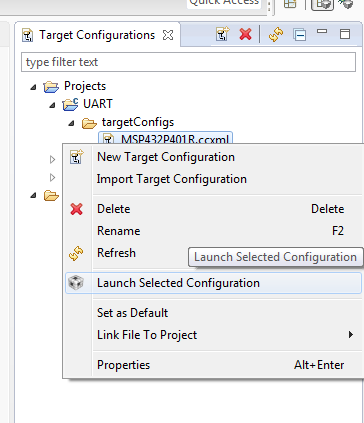
    go to view->target configurations

    Launch Selected Configuration for your project

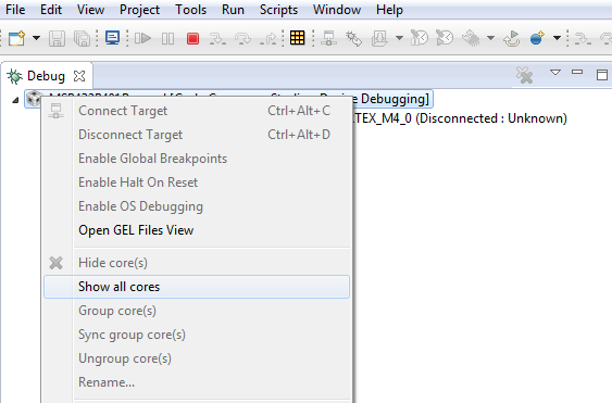
    Right click the .ccxml in the debug window and press show all cores

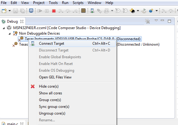
    Connect to the DAP_0

    Go to Scripts->default->factory reset

    Have you tried this yet?

  • I tried doing this, and while connecting I again get his error:

    Error connecting to the target:
    (Error -1170 @ 0x0)
    Unable to access the DAP. Reset the device, and retry the operation. If error persists, confirm configuration, power-cycle the board, and/or try more reliable JTAG settings (e.g. lower TCLK).
    (Emulation package 6.0.628.1)

    No connection possible. This could be caused by the device having gone to low power mode and disabling JTAG PINs.
    You have the option to either toggle reset or try to use SWD instead.

  • Please send the picture you were saying you could send along with any schematics you have related to the debugging pins.
  • Have you tried to switch your debugger to SWD instead of JTAG protocol before executing the factory reset?
    SWD uses only two pins which can't be configured, so this should always be possible.

    In newer versions of CCS this should be the standard protocol for MSP432.

    After successful factory reset the access to the device with JTAG should be possible again.


    Regards,

    Thorsten

  • Hello everyone,

    I am very thankful for all the answers and questions I got. We found out the problem of our problem, at least for one part of the problem.

    For some reason, toggling reset didn't help. We even tried manually holding the MCU in reset but that also did not help to factory reset or just get the MCU into debugging in the JTAG 4-pin standard mode.

    We are using the upper half of the MSP432P401R red Launchpad as our debugging module(XDS110) and with a JTAG cable, we connected it to one little board which had voltage shifters and diodes and that little board we connected to our MCU.

    The problem was that we put a diode on the SWDIOTMS pin which made it only output but it had to be bidirectional. When we removed the diode, the SWD mode worked and we got to access the MCU.

    Thanks again for the help and I hope that this will maybe help anyone in the future.

**Attention** This is a public forum