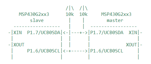
Hi I m trying to simulate an interface between msp430g2553 and an OLED display (powered by ssd1306 ) I have attached the code below , can anyone tell me why is it that the port one is set to low even though the PINSEL function sets p1.6 and p1.7 for I2C ?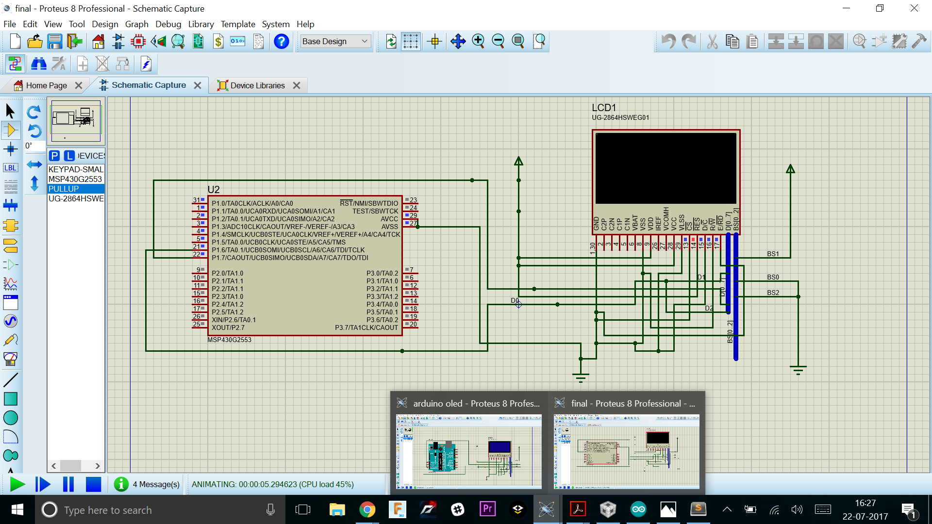
#include <msp430.h>

/*
0xAE,  // Display off
0x81,  // set contrast controll register
0x7F,  // contrast Wert 127 ok

0x20,  // Set Memory Adress Mode
0x01,  // Vertical Adressing Mode

0x21,  // Set Column Adress
0x00,  // Start Adress 0
0x7F,  // End Adress 127

0x22,  // Set Page Adress
0x00,  // Start Adress 0
0x07,  // End Adress 7

0x40,  // set start line adress 0

0xA0,  // Column Adress mapped to SEG0

0xA8,  // set multiplex ratio
0x3F,  // maximum

0xC0,  // Set COM Output Scan Direction to normal mode

0xD3,  // set display offset
0x00,  // 0

0x8D,  // Set Charge Pump Setting
0x14,  // ON

0xDA,  // set com pins hardware conf
0x12,  // alternative + disable remap

0xD5,  // set display clock divide + freq
0x80,  // divide by 1 and medium freq

0xD9,  // set pre charge preriod
0x22,  // medium (reset value)

0xDB,  // set vcomh
0x20,  // 0.77 x Vcc

0xA4,  // Output follows RAM Content

0xAF  // Display on*/


const unsigned char Init[] = {0xAE,0x81,0x07,0x20,0x01,0x21,0x00,0x7F,0x22,0x00,0x07,0x40,0xA0,0xA8,0x3F,0xC0,0xD3,0x00,0x8D,0x14,0xDA,0x12,0xD5,0x80,0xD9,0x22,0xDB,0x20,0xA6,0xA4,0xAF};

//const unsigned char Init[] = {0xAE,0x81,0x07,0x20,0x01,0x21,0x00,0x7F,0x22,0x00,0x07,0x40,0xA0,0xA8,0x3F,0xD3,0x00,0x8D,0x14,0xD5,0x80,0xD9,0x22,0xDB,0x20,0xA6,0xA4,0xAF};


const unsigned char Mod[] = {0xA5};

unsigned int i = 0;
//unsigned int I = 0;

void printC(const unsigned char* Array, unsigned int length){

	UCB0CTL1 = UCSWRST;
	UCB0CTL0 = UCMODE_3 + UCMST + UCSYNC;			// I2C master mode
	UCB0CTL1 = UCSSEL_2 + UCSWRST; // Use SMCLK, keep SW reset
	UCB0BR0 = 0x40;                          // < 100 kHz
	UCB0I2CSA = 0x3C;                       // address
	UCB0CTL1 &= ~UCSWRST;
	IE2 |= UCB0TXIE;				// Enable TX ready interrupt
	__disable_interrupt();
	UCB0CTL1 |= UCTR + UCTXSTT; // I2C TX, start condition


	__bis_SR_register(LPM3_bits + GIE);

	unsigned int c;
	for(c = 0; c < length; c++){
		//__bis_SR_register(LPM3_bits + GIE);
		UCB0TXBUF = 0x80;
		__bis_SR_register(LPM3_bits + GIE);
		UCB0TXBUF = Array[c];
		__bis_SR_register(LPM3_bits + GIE);
	}

	UCB0CTL1 |= UCTXSTP;
	IE2 &= ~UCB0TXIE;

}

void printS(void){
	UCB0CTL1 = UCSWRST;
	UCB0CTL0 = UCMODE_3 + UCMST + UCSYNC;			// I2C master mode
	UCB0CTL1 = UCSSEL_2 + UCSWRST; // Use SMCLK, keep SW reset
	UCB0BR0 = 0x40;                          // < 100 kHz
	UCB0I2CSA = 0x3C;                       // address
	UCB0CTL1 &= ~UCSWRST;
	IE2 |= UCB0TXIE;				// Enable TX ready interrupt
	__disable_interrupt();
	UCB0CTL1 |= UCTR + UCTXSTT; // I2C TX, start condition

	__bis_SR_register(LPM3_bits + GIE);;
}

void printD(const unsigned char Data){
	UCB0TXBUF = Data;
	__bis_SR_register(LPM3_bits + GIE);
}

void printE(void){
	UCB0CTL1 |= UCTR + UCTXSTP;
}


void main(void){
    WDTCTL = WDTPW + WDTHOLD;

    DCOCTL = CALDCO_8MHZ;				//DCO setting = 8MHz
    BCSCTL1 = CALBC1_8MHZ;				//DCO setting = 8MHz

    // Configure Pins for I2C
    P1SEL |= BIT6 + BIT7;                  // Pin init
    P1SEL2 |= BIT6 + BIT7;                  // Pin init


    printC(Init,31);

    __delay_cycles(8000000);

    printC(Mod,1);

    /*
    printS();


    UCB0TXBUF = 0x00;
    __bis_SR_register(LPM3_bits + GIE);


    unsigned int i;
    for(i = 500; i > 0; i--){
    	printD(0xFF);
    	printD(0x00);
    }
    printE();*/

    while(1);

}


// USCI_B0 Data ISR
#pragma vector = USCIAB0TX_VECTOR
__interrupt void USCIAB0TX_ISR(void){
	IFG2 &= ~UCB0TXIFG;
	__bic_SR_register_on_exit(LPM3_bits);               // Wakeup main code
}