This thread has been locked.

If you have a related question, please click the "Ask a related question" button in the top right corner. The newly created question will be automatically linked to this question.

MSP430F5324: LDONIFG flag and LDOONIE Interrupt not being generated.

Part Number: MSP430F5324

I am trying to use the LDOONIFG flag and LDOONIE interrupt to indicate when there is adequate power on the LDOI pin.

According to the MSP430 User Manual the LDOONIFG flag can be used to indicate that the supply voltage on LDOI has risen above the launch voltage. In addition ot this flag an interrupt should be generated when LDOONIE is set.

Unfortunately these two signals (along with the LDOOFFFG flag and LDOOFFIE Interrupt enable) do not seem to function without the LDO PWR module being enabled by having LDOEN set to 1.

Is there a way that I can have the LDOONIFG flag be active without turning on the LOW PWR? I would like to detect a change of state for the power without having the extra power consumption of have the LDO PWR turned on.

  • Hi Thomas,
    Let me check on that.

    What are you trying to do here?
    Are you trying to use the LDO interrupts like a comparator?
    Do you have test code for what your are doing?
  • I have an application where my primary power is supplied to the LOI input on the MSP430. The LDOO output and a backup battery is then connected to DVCC. When primary power is lost I receive an interrupt from LDOOFFIFG. The ISR then places the MSP430 into LPM4 mode. While in LPM4 mode the DVCC is held up by the backup battery. The unit stays in LPM4 mode until primary power is restored (days or weeks later).

    To recover from LPM4 mode and return to active mode I need an interrupt. I am trying to generate that interrupt as an indication that primary power has been restored and is valid. Per the user manual this is the exact function that the LDOONIFG flag seems to be designed to indicate.

    The LDOONIFG will cause an interrupt when primary power (on the LDO pin) returns to a valid state but this only happens if the LDO is enabled. If the LDO is not enabled then LDOONIFG will not cause an interrupt. The problem is power consumption. When the LDO is enabled in LMP4 mode the power consumption on DVCC  is more than 190uA vs a current draw of 1.2uA while in LPM4 mode with the LDO disabled.

    To provide the maximum amount of standby time while in LMP4 mode I need to reduce the current drain to a minimum.

    As a work around to the LDOONIFG interrupt issue, I have reconfigured the circuit to supply 3.3 volts to a P2 pin when primary power is available. While in LMP4 mode the P2 pin is set to generate an interrupt when primary power is restored. This interrupt can then terminate LMP4 mode and return the processor to active mode. This approach still maintains the 1.2uA low power consumption. Only problem is I have to use an extra P2 pin to accomplish it. Would be nice it the LDOONIFG worked without the LDO being enabled.

    Is there any way to use the LDOONIFG flag without having the LDO enabled?

  • Thomas,
    Can you walk me through how you are measuring the current?
    The debugger (EEM) should be disengaged (free run), as it consumes power. The voltage on LDOI should be less than 3.75, (or preferably GND). This should place the LDO in Suspend.

    User Guide section 43.2.1 states that
    "If the voltage on LDOI is detected to be low or nonexistent, the LDO is suspended even if enabled by LDOEN = 1. No
    additional current is consumed while the LDO is suspended."
  • Please let me know if this is not the case. I already have a systems team investigating the interrupt gating , so it shouldn't be to much trouble for them to check this out as well.
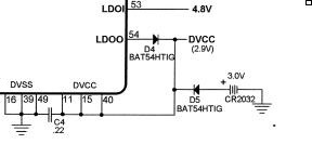
  • Below I've show how the primary (4.8Volts) and secondary (3.0V battery) power are connected. When the 430 is in LPM4 mode I measure the current draw from the 3 volt battery (Measure the voltage across a 1.5k ohm resistor that is in series with the 3.0 volt battery. During this measurement the JTAG is disconnected. The 430 is in the circuit as it would be in the field. The LDOI voltage is 0Volts in this state.

    I agree that the User Guide says that the LDO is suspended but there is additional current draw when LDO is enabled and LDOI = 0V than when LDO is not enabled and LDOI = 0. Seems that suspended does not mean no power consumption by the LDO.

    Per TI document SLAS678D-August 2010-Revised February 2013 for the MSP430F532x on pg 43 it shows that the power consumption in LPM4 is conditioned by notes 4 & 8. Note 8 shows that to get this low power consumption the LDOEN needs to be set to 0 (LDO disabled). And that agrees with my findings. With LDO diabled I get the lowest power consumption.

    My questions is why do the LDOONIFG and LDOOFFIFG flags need the LDO to be active for those flags to be updated. Note I since determined that LDOBGVBV flag is also not functional if the LDO is disabled.

  • Hi Thomas,
    I'm working on this internally. I'll update you as soon as I have an answer.
  • Thomas,
    I just wanted to let you know, I'm waiting for the systems team to get back to me, but this hasn't been forgotten.
  • Thomas,
    I apologize for the very lengthy delay. We had to dig into the design files.

    It appears this behavior is to be expected, as the LDO powers that entire module. I will see to it that this is either fixed or noted in the user guide.

    So the trade off is that you can go to LPM4 and power down the LDO to save power and wake using an external monitor or GPIO to monitor the LDOI signal. Or, you could go to LPM3 and wak up occaisionally to enable to LDO to check if power has returned.
  • Thanks for the reply. To work around the issue I've power down to LPM4 and then used a GPIO pin to monitor the voltage. That has work reliably for the past 2 months.

**Attention** This is a public forum