This thread has been locked.

If you have a related question, please click the "Ask a related question" button in the top right corner. The newly created question will be automatically linked to this question.

MSP430FR6047: FR6047-EVM GUI

Part Number: MSP430FR6047

I am using FR6047 GUI,but some params amazing me so much,what are the flowing three params means??? 

i have read the GUI's user guid,but steal do not know  what the three params means,espically  "start PPG count", can TI employee give me a teach.?

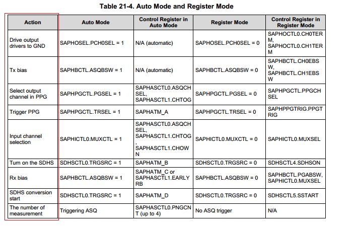
2.’from the following picture in the silicon user guid,it is easy to understand the time pierod  of  the USS works,but the GUI's describtion is so bad!

from the silicon user guid, the "Trigger PPG" means start to generate  and stop pluse, but what the "start PPG count" in the GUI means?

3.it is better to using the figure to teach me what is the three params means  like this 

  • Hello,

    There are a few documents to reference on these time marks.  

    Section 21.4 of users guide:  

    Design Center Users Guide: 

    USS Library API Guide: C:\ti\msp\USSLib_01_20_00_14 (if installed in default location)

    Please see table 21-3 in the silicon users guide.  TM_A through TM_D represent the different time mark events where TM_A through TM_C are directly represented from the GUI configuration.  TM_D can be calculated with TM_A + Gap between pulse start and ADC Capture(default =62uS).  Let me know if you still need some clarification and we can see about putting this together as a timing diagram as well.

  •  hi

    eddie

     i do not think GUI's user guide describe the params clearly,

    to be opposite, GUI's description  may mistake the user

    for example ,for the"UPS and DNS Gap ", the GUI's user guide says "Time between between ADC captures in a sequence in microseconds ".

    i am fused, this params just means the pulse Gap between two transducers, it have nothing to with ADC capture. what is your opinion?

    2、what is different between the  "start PPG Count" and "UPS0 to UPS1 Gap"  ?    and why "Turn on ADC count "is shorter than "Start PPG Count"? as my opinion,it should be longer,because we generate pulse first followed by adc capture.

    i can read the silicon user guide("Six Time Mark Events") clearly and understand what it means,but the GUI's description is so mass.

    for the two answer above , i need the deep support not give me the user guide,thanks!

    and i need the a timing diagram to describe the association between the "Six Time Mark Events" and the params in the GUI

  • Hello,

    Thanks for the feedback and we will clarify the time mark events and how they correlate to the GUI in the documentation.

    In regards to UPS and DNS Gap description in the user’s guide, it does not state “ADC captures”, but does state “time between captures in a sequence”.  This is referring to the time between UPS pulses and DNS pulses.  I agree that this does not refer to ADC capture.  We can change the wording in the documentation to clarify.

     The time marks do not necessarily need to be sequential TMA to TMD.  This will be system dependent.  For the specific “off the shelf” Audiowell pipe and EVM hardware we test with, we found that turning on the ADC slightly before Start PPG provided better results.  Feel free to adjust this based on your system requirements for best performance.

    Please see the relationship below between the time marks from the user’s guide and the GUI.      

    TMA – Start PPG

    TMB – Turn on ADC count

    TMC – Start PGA and IN Bias Count

    TMD - TM_A + Gap between pulse start and ADC Capture

  • hi Eddie
    thanks for your reply.
    so the actual time interval between the sequences is T="UPS0 to UPS1 Gap" + "start PPG count".
    it is important to me beacuse i will use this interval time to accumulate the volume of the water.
    where the delta volume = interval time * flow rate.
    am i right?
  • hi eddie,

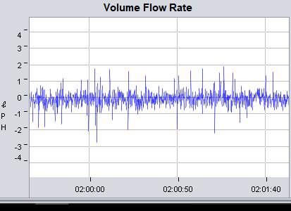
    there are so many noise signal(no flow) in the flow rate,how to avoid it?

  • Hi,

    The raw computed volume flow rate will in general be noisy. You can run a smoothing filter on these raw measurements to obtain a smoothed average flow rate.

    Srinivas

  • Hi Kissn,

    Did this help answer your questions? Or is there more that we can do to help?

    Regards,
    Katie

**Attention** This is a public forum