This thread has been locked.

If you have a related question, please click the "Ask a related question" button in the top right corner. The newly created question will be automatically linked to this question.

MSP430F149: MSP430F149 AD Voltage abnormality

Part Number: MSP430F149
Other Parts Discussed in Thread: INA193, MSP-TS430PM64

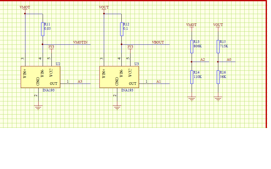
With A1 to A3 four AD acquisition, only the smallest system with the voltage divider resistor, configured into ad's special function pin, A3 port always maintain a voltage of more than 2v, for another chip, began normal, After a period of time the chip can not work, please help me analyze this problem,THANKS!!

  • Hi Jason,

    It is difficult to identify your issue given the minimal amount of information provided. Please provide more details such as supply voltage, operating frequency, initialization code, schematic, board layout images, debugging efforts, and logic analyzer or oscilloscope screenshots.

    Regards,
    Ryan
  • void ADC_Init(void)
    {

    P6SEL = 0x0F; // Enable A/D channel inputs
    ADC12CTL0 = ADC12ON+MSC+SHT0_8+REFON+ REF2_5V; // Turn on ADC12, set sampling time
    // ADC12CTL0 = ADC12ON+MSC+SHT0_8+REFON;
    // ADC12CTL0 = ADC12ON+MSC+SHT0_8;
    // ADC12CTL1 = SHP+CONSEQ_1; // Use sampling timer, single seq
    ADC12CTL1 = SHP+CONSEQ_1+ADC12SSEL_2+ADC12DIV_7;
    ADC12MCTL0 = SREF_1+INCH_0; // ref+=AVcc, channel = A0Protel Schematic1.pdf
    ADC12MCTL1 = SREF_1+INCH_1; // ref+=AVcc, channel = A1
    ADC12MCTL2 = SREF_1+INCH_2; // ref+=AVcc, channel = A2
    ADC12MCTL3 = SREF_1+INCH_3+EOS; // ref+=AVcc, channel = A3, end seq

    ADC12IE = 0x08; // Enable ADC12IFG.3
    ADC12CTL0 |= ENC; // Enable conversions

    this is tne adc init code.

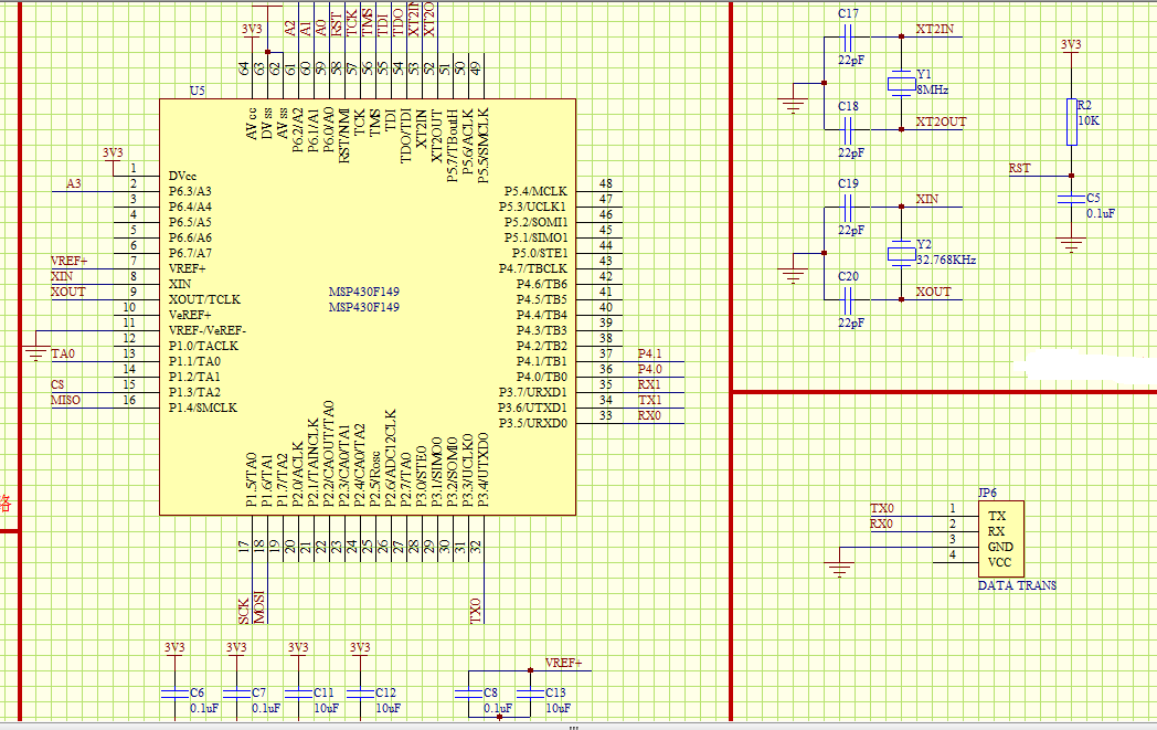
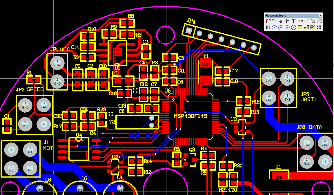
  • Now the board welding the smallest system, with the first burner burn program can burn in, and then sometimes run the program for some time, sometimes not directly, out of online debugging, the second time to see the device can not find, it is probably a board problem, but my schematic is no problem, Does the quality of PCB layout will affect so much?

    layout and sch

    THANKS!!

  • Hi Jason,

    Nothing in your ADC initialization code indicates an issue that would cause the MSP430 to crash, and your schematic looks fine as well (reduce C5 to 1 or 2.2 nF). Is the issue that the ADC readings are incorrect or is the CPU freezing/restarting? Are you able to easily reproduce the issue? Is the board exposed to any temperature or humidity changes? We need to ensure that your crystals are still oscillating by observing the XT pins and respective clock source output signals. Crystal debugging is provided in SLAA322: www.ti.com/.../slaa322c.pdf

    Regards,
    Ryan
  • I used five boards to test, only one is normal, the other four are problematic, some program can be normal operation, but the A3 has been a 2V to 3.3V (VCC) voltage, and some programming the program stops at IFG1 & = ~ OFIFG when debugging online,this is IAR resport:Fri Sep 08, 2017 09:00:34: Internal error : (State) , state=0x1, stop=0x1, cycles=0x602e068  .

    and the device can not be found when downloading the program again.Is the incorrect code can damage the device?

  • If the code is stuck inside the fault flag loop then this indicates an issue with your crystal oscillators, oscilloscope probes could confirm that XT1/XT2 are not oscillating properly. Please review SLAA322 and confirm your clock setup, load capacitance, and board layout practices. You might try an A-B-A test to see if the issue follows the crystal, board, or MCU.

    Regards,
    Ryan
  • hi Ryan,

    I use the X2 external high-speed crystal,those  boards who can not use  before, it can normal debugging now , but I did not have any changes. The problem now is that all of A0 to A3 have a high voltage of 3v. I put them into input mode, they are still 2v to 3v fluctuations. When I put them configured to output low, A3 still has a fluctuation voltage of about 0.5v.

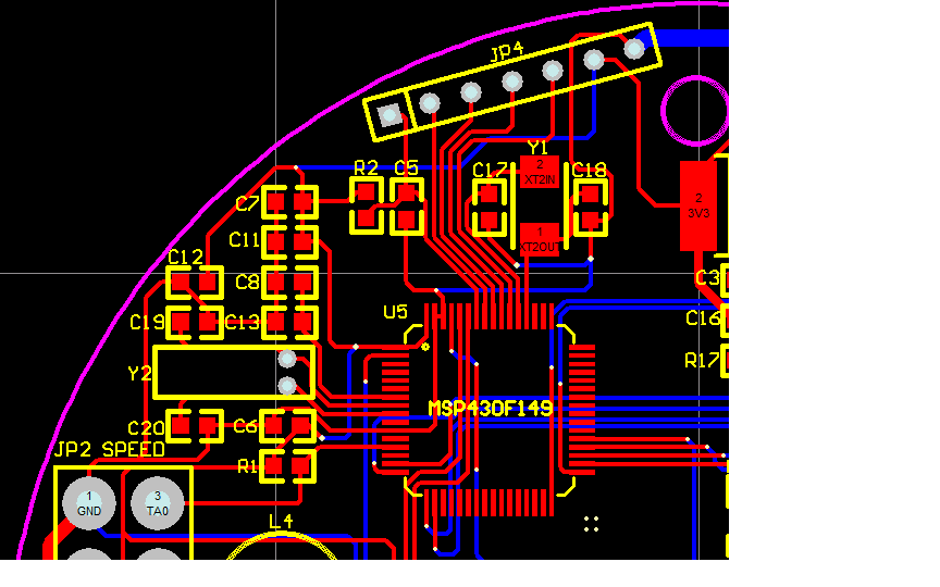
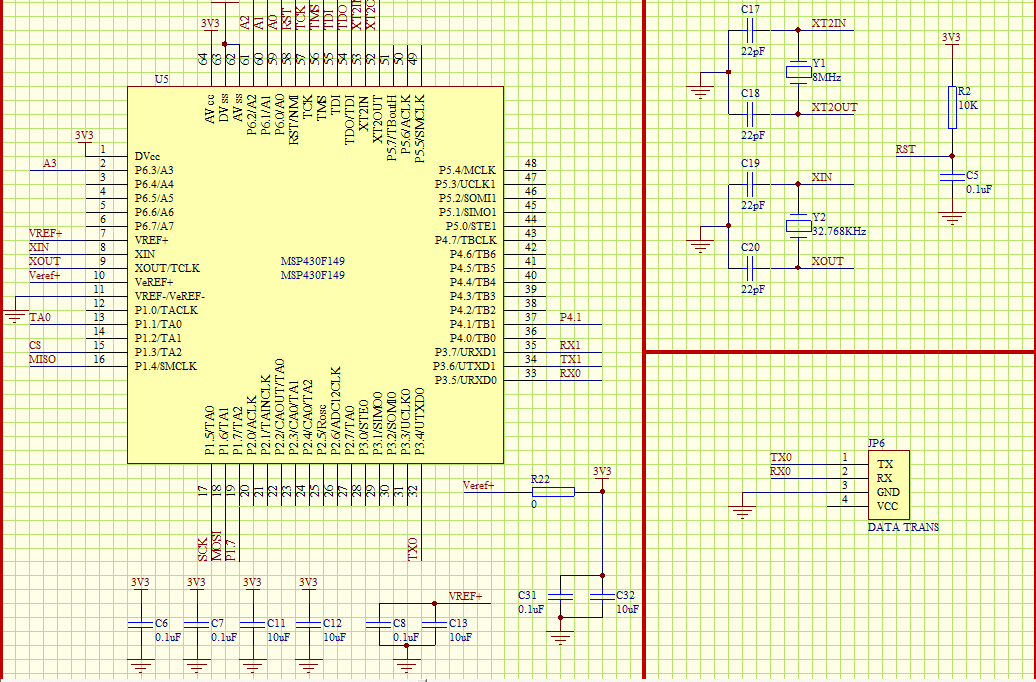
    I have re-designed a new board, the problem still exists, AD port is still 2v to 3v voltage.

    sch

    PCB

    Please help me look at what may affect the normal work of AD, thank you!

    Best regards!

  • Hi Jason,

    Nothing from your schematic or layout is immediately concerning. Are you interpreting these voltages from ADC12MEMx? You should check the analog pins with an oscilloscope and see whether the inputs actually are fluctuating (analog hardware design issue) or if the ADC cannot interpret the inputs. You can alter the sample-and-hold time or timer frequency to see if this makes any changes to your system.

    Regards,
    Ryan
  • Hi Ryan

    I checked the voltage of the pin with an oscilloscope, which really came from the pin and was indeed a floating voltage, and the AD acquisition function was normal because he could indeed collect the voltage. However, this voltage should be the output of the MSP430 pin. Because when the external voltage divider resistance is not voltage access, the pin still exists on this voltage. When I removed the MCU, the voltage disappeared. alter the sample-and-hold time or timer frequency looks like nothing different.

    Best Regards!

  • Hi Jason,

    There is a fundamental issue with setting P6.1/P6.3 to output mode when they are connected to the outputs of INA193. P6.0/P6.2 should likewise not be driven out as this conflicts with the voltage supplies they are connected to through the resistive divider. You may need to revise your schematic to accomplish your application.

    Regards,
    Ryan
  • I do not quite understand what you mean, I would like to use these four AD port to collect external voltage, we need configured here into a special function mode,right?

    but in these mode,there is always have a 2V to 3V voltage in A3.

  • Yes, P6SEL bits set. Can you replicate this behavior on a MSP-TS430PM64 EVM? Please perform a continuity check to make sure that P6.0 is not shorted to the surrounding pins, like RST.

    Regards,
    Ryan
  • Finally,the problem has been solved! it takes me one mouth.
    FULX!!!!
  • Hi Ryan,there is another question.
    When I use the MSP-FET430UIF to run the program online, the program can run properly, and then connected to the battery at this time, remove the MSP-FET430UIF, MCU is still working properly. However, when I directly use the battery to provide the power. the MCU does not work.
    would you give me some advice for this?
    Best regards!
  • Hi Jason,

    I'm glad to hear about your progress. Can you specify what caused the issue and how was the problem solved?

    What is the battery supply voltage and system operating frequency? What is the VCC rise time when the battery is connected and can you verify this with an oscilloscope screenshot? Please refer to Figure 1 (Frequency vs Supply Voltage) of the device datasheet and provide system initialization code if possible.

    Regards,
    Ryan
  • Hi,Ryan

    The last problem is because I used oily flux(i do not know the accurate expression in english), it may have a small conductivity, and will not cause a short circuit, but will affect the voltage.

    this problem,i have not a oscilloscope now,when the battery is connected,the MCU does not work,and then i  touch the RST and GND with a wire and it works normally.

    Best regards!

  • Hi Jason,

    There appear to be system start-up issues involved that require a manual reset to get the system properly running again. It is possible that the main frequency is increased before the MCU is fully powered by the battery, causing it to fail. Or there could be further flux issues. You should debug by placing a long delay at the beginning of your main while loop, fully cleaning your board, and obtaining an oscilloscope.

    Regards,
    Ryan
  • Hi Ryan,

    Is there have possibility that caused by not enough reset hold time? Dose it help if i use a reset monitors?

    i have a long delay at the beginning of the main while loop.about 500ms,Is it enough?

    Best regard!

  • Hey Jason,

    The reset timing is definitely worth investigating, especially since this device does not include a BOR. You should refer to Figure 10 of the Datasheet for power-up timing specifications. A reset monitor could be beneficial if this is indeed the issue.

    500 ms should be plenty for the purpose of debugging, you can also look at Figure 12 for DCO characteristics.

    Regards,
    Ryan
  • Hi,Ryan
    Thank you for your solution, the problem has been solved, there is a serial monitor connection with computer when i debugging, resulting in vcc power is not complete removed.There is no problems when i removed all the external devices.
    Regards.

**Attention** This is a public forum