This thread has been locked.

If you have a related question, please click the "Ask a related question" button in the top right corner. The newly created question will be automatically linked to this question.

MSP430F149: AD acquisition error

Part Number: MSP430F149

I use the MCU itself AD, the reference voltage is 2.5v internal,  measure the voltage by resistor divider .There is about 4mv error between the collected value and the actual value , and the higher the voltage, the greater the error. What is the reason for the general causeof it? Whether there is an influence of the input impedance and the output impedance  
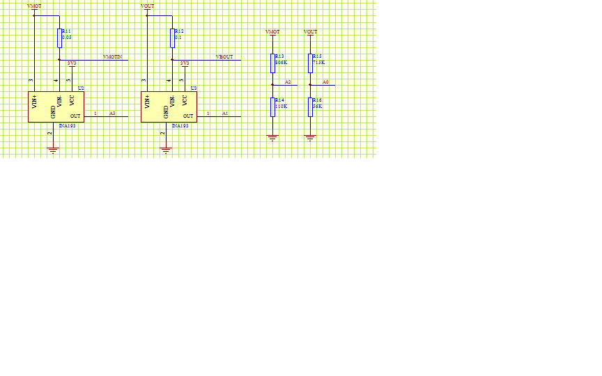
  • Hi Jason,

    How are you measuring the actual voltage and how confident are you of its accuracy? The error could be due to tolerances of the physical resistors. It is also worth noting that VREF+ is typically 2.5 V but could vary between 2.4 and 2.6 V which could contribute to the error.

    Regards,
    Ryan
  • Hi,Ryan

    I used the Voltmeter to measure the voltage,vref + measured with a voltmeter is stable, I have in the program with the actual measured voltage as the reference voltage.and I measured the voltage directly on the AD pin,so we do not have to consider the tolerances of the physical resistors.

    Best regards!

  • Hey Jason,

    Please provide some examples of the measured VREF+ voltage, measured AD pin voltage, and resultant ADC measurement. Is initialization the same as your other E2E request? e2e.ti.com/.../

    Regards,
    Ryan
  • Hi Ryan,

    when the vref+ is 2.485v,the measured AD pin voltage is 0.845,and now the resultant ADC measurement is 0.848.there is 0.003v

     error.It bigger when the AD pin voltage increase.

    the initialization is same as before.

    Regards!

  • Hey Jason,

    Please provide raw ADC readings from ADC12MEMx and the equation used for conversion. It appears that you are within the linearity error parameters, you could attempt to improve this by further increasing the sample-and-hold time or take an average of samples (oversampling).

    Regards,
    Ryan
  • Hi Ryan,

    this is the equation used for conversion.and i take an average of 15 samples.

    A0=A0/4095.0*2.4855;

    A0 is the raw ADC reading from ADC12MEMx.

     ADC12CTL0 = ADC12ON+MSC+SHT0_8+REFON+ REF2_5V; 

    the sample and hold time is SHT0_8,and there is no help when i  increase this to  SHT0_10 or something else.

    Regards!

  • Make sure that A0 is a long floating variable and multiply 2.4855 before dividing by 4096. You may even want to measure in mV instead of volts so that you can use integer math. VREF+ will vary on each MSP430 so this equation will introduce some error regardless. It also explains why you notice a linear increasing with voltage input. I suspect that the raw ADC readings are as expected with maximum 5 LSB error described in the linearity parameters of the datasheet.

    Regards,
    Ryan

**Attention** This is a public forum