This thread has been locked.

If you have a related question, please click the "Ask a related question" button in the top right corner. The newly created question will be automatically linked to this question.

MSP430G2553: information memory maybe erased or changed when update program by BSL

Part Number: MSP430G2553

HI,

using CPU to update the G2553 program success by BSL, but information memory maybe erased or changed. I haven't found the reason, can you give some advise.

I tried three ways:

1.mass erase->send right password->send bin file data

2.send right password->Erase segment->send bin file data

2. send wrong password->send right password->send bin file data

thank!

mcu-upgrade.c
#include <sys/stat.h>
#include <unistd.h>
#include <sys/mman.h>
#include <time.h>
#include <stdio.h>
#include <stdlib.h>
#include <fcntl.h>
#include <termios.h>
#include <errno.h>
#include <string.h>

typedef unsigned char u8;
typedef unsigned short u16;

#define MCU_ACK     0xFA
#define MCU_TEST    0xFB
#define MCU_START   0xFD
#define MCU_END     0xFE
#define MCU_TIMEOUT     (-1)

#define MCU_DATA_IDX        3

#define DATA_CMD_LEN        1
#define DATA_PORT_LEN       1
#define DATA_VOLTAGE_LEN    2
#define DATA_CURRENT_LEN    2
#define DATA_VERSION_LEN    2

#define MSG_MAX_LEN         64
#define MSG_HEADER_LEN      (1 + DATA_CMD_LEN + DATA_PORT_LEN)
#define MSG_END_LEN         (1)
#define MSG_LEN_GET_VC      (MSG_HEADER_LEN + DATA_VOLTAGE_LEN + DATA_CURRENT_LEN + MSG_END_LEN)
#define MSG_LEN_GET_VERSION (MSG_HEADER_LEN + DATA_VERSION_LEN + MSG_END_LEN)

#define MTK_GPIO_BASE     0x1E000600
#define MTK_GPIO_CTL_OFF  0
#define MTK_GPIO_WIDTH    0x100
#define MTK_GPIO_SET_OFF  0x30
#define MTK_GPIO_CLR_OFF  0x40
#define BSL_EN            16
#define BSL_RST           14
#define BSL_TEST          13
#define BSL_DEALY         60
#define MCU_MAX_BIN       (64 * 1024) /* FLASH 16K */

#define UPGRADE_TRUNK     128

#define MCU_UPGRADE_FILE  "/tmp/mcu-upgrade.tmp"
#define DEV_MCU_PATH      "/dev/ttyS0"

#define CMD_RX_DATA_BLOCK      0x12
#define CMD_RX_PASSWORD        0x10
#define CMD_PASSWORD_LEN       0x20
#define CMD_ERASE_SEGMENT      0x16
#define CMD_ERASE_MAIN_INFO    0x16
#define CMD_MASS_ERASE         0x18
#define CMD_ERASE_CHECK        0x1C
#define CMD_TX_BSL_VER         0x1E

#define CMD_MAX_BYTES          0x104  /* �������ȣ�8+250+2 */
#define MCU_FLASH_START        0xC000 /* flash��д����ʼ��ַ */
#define BSL_SYNC               0x80
#define BSL_ACK                0x90
#define BSL_NAK                0xA0
#define BSL_RECEIVE_TIEMS      10
#define CMD_RETRY_TIME         3

enum {
    MCU_CMD_PORT_CONTROL = 1, //power on/off one port
    MCU_CMD_SET_SYS_POWER = 2, 
    MCU_CMD_GET_PORT_STATUS = 3,
    MCU_CMD_GET_VC = 4,
    MCU_CMD_GET_PD_CLASS = 5,
    MCU_CMD_GET_ALL = 6,
    MCU_CMD_GET_VERSION = 7,
    MCU_CMD_ALLPORTS_CONTROL = 8, //power on/off all ports

    MCU_CMD_MAX,
};

static int mcu_bsl_sync(void)
{
	u8 cmd_buf[1];
	int ret, retry_time = 0;
	int recvtimes, flag;
	
retry_sync:
    recvtimes = 0;
	flag = 0;
	/* send 0x80 */
	cmd_buf[0] = BSL_SYNC;
	mcu_send_msg(cmd_buf, 1);
	
	ft_udelay(10 * 1000);
	
	printf("%s: send BSL_SYNC\n", __func__);
	

	do {
		ret = mcu_recv_msg(cmd_buf, 1);
		flag = (recvtimes++ < BSL_RECEIVE_TIEMS) && 
		        (ret != 1 || (cmd_buf[0] != BSL_ACK && cmd_buf[0] != BSL_NAK));
		if (flag) {
			ft_udelay(10*1000);
		}		
	} while (flag);
	
	if (ret != 1 || cmd_buf[0] != BSL_ACK) {
		printf("%s: SYNC fail, ret:%d, cmd_buf[0]:0x%x\n", __func__, ret, cmd_buf[0]);
		if (retry_time++ < CMD_RETRY_TIME) {
			goto retry_sync;
		}
		return -EIO;
	}

	printf("%s: sync success\n", __func__);
	
	return 0;
}

static int mcu_bsl_command(u8 cmd, u8 l1, u8 l2, u8 al, u8 ah, u8 ll, u8 lh, u8 *data, int num, int udelay)
{
	u8 cmd_buf[CMD_MAX_BYTES];
	int ret, retry_time = 0;
	int recvtimes, flag;
	
    ret = mcu_bsl_sync();
	if (ret)
		return ret;

retry:
    recvtimes = 0;
	flag = 0;
    ret = bsl_cmd(cmd_buf, cmd, l1, l2, al, ah, ll, lh, data, num);
	mcu_send_msg(cmd_buf, ret);
	
	ft_udelay(udelay);
	
	do {
		ret = mcu_recv_msg(cmd_buf, 1);
		flag = (recvtimes++ < BSL_RECEIVE_TIEMS) && 
		        (ret != 1 || (cmd_buf[0] != BSL_ACK && cmd_buf[0] != BSL_NAK));
		if (flag) {
			ft_udelay(10*1000);
		}		
	} while (flag);
	
	if (ret != 1 || cmd_buf[0] != BSL_ACK) {
		printf("%s: %s fail, ret:%d, cmd_buf[0]:0x%x\n", __func__, bsl_cmd_name(cmd), ret, cmd_buf[0]);
		if (retry_time++ < CMD_RETRY_TIME) {
			ft_udelay(300*1000);
			goto retry;
		}
		return -EIO;
	}
	printf("%s: %s success\n", __func__, bsl_cmd_name(cmd));
	
	return 0;
}

int mcu_low_upgrade(u8 *bin, int size)
{
	u8 password[CMD_PASSWORD_LEN], tmp_buf[CMD_MAX_BYTES];
	int ret, i;
	u16 start;
	
	printf("%s: size:%d\n", __func__, size);
	
	//send wrong password
	memset(password, 0xff, CMD_PASSWORD_LEN-2);
	memset(password+CMD_PASSWORD_LEN-2, 0x00, 2);
		ret = mcu_bsl_command(CMD_RX_PASSWORD, 0x24, 0x24, 0, 0, 0, 0, password, CMD_PASSWORD_LEN, 10*1000);
	if (ret) 
		return ret;
	
	ret = mcu_bsl_command(CMD_MASS_ERASE, 0x04, 0x04, 0, 0, 0x06, 0xA5, NULL, 0, 300*1000);
	if (ret) 
		return ret;
	
	//send right password
	memset(password, 0xff, CMD_PASSWORD_LEN);
	ret = mcu_bsl_command(CMD_RX_PASSWORD, 0x24, 0x24, 0, 0, 0, 0, password, CMD_PASSWORD_LEN, 10*1000);
	if (ret) 
		return ret;
	
	
	printf("%s: start write bin\n", __func__);
	start = MCU_FLASH_START;
    /* start download bin */
	for (i = 0; i < size; i += UPGRADE_TRUNK) {
		memcpy(tmp_buf, bin+i, UPGRADE_TRUNK);
		ret = mcu_bsl_command(CMD_RX_DATA_BLOCK, UPGRADE_TRUNK+4, UPGRADE_TRUNK+4, 
		        (start+i) & 0xff, ((start+i) >> 8) & 0xff, UPGRADE_TRUNK, 0, tmp_buf, UPGRADE_TRUNK, 500*1000);
        if (ret)
			return ret;
		
        printf("%s: write bin 0x%x success\n", __func__, start+i);	
	}
	printf("%s: start write bin all success\n", __func__);
	
	/* download over */
	
	return 0;
}

int mcu_check_upgrade(void)
{
	unsigned char version, patchlevel;

    if (poe_get_version(&version, &patchlevel)) {
        printf("MCU Version: unknown\r\n");
        return -1;
    }

    printf("MCU Version: %d.%d\r\n", version, patchlevel);	
	return 0;	
}

int mcu_upgrade_routine(void)
{
	struct stat buf;
	int fd, size, ret;
	u8 *bin;
	
	fd = open(MCU_UPGRADE_FILE, O_RDONLY);
	if (fd < 0) {
		printf("No MCU upgrade file, return!\n");
		return -ENOENT;		
	}
	memset(&buf, 0, sizeof(stat));
	stat(MCU_UPGRADE_FILE, &buf);
	size = buf.st_size;
	
	if (size > MCU_MAX_BIN) {
		printf("MCU upgrade bin size is %d, too big!\n", size);
		close(fd);
		return -EINVAL;
	}
	bin = malloc(size);
	if (bin == NULL) {
		printf("%s: malloc %d fail\n", __func__, size);
		close(fd);
		return -ENOMEM;
	}
	ret = read(fd, bin, size);
	if (ret != size) {
		printf("%s: read fail, size:%d, ret:%d\n", __func__, size, ret);
		close(fd);
		free(bin);
		return -EIO;
	}
	close(fd);
	
	/* first disable jtag��use gpio 13 14 15 */
	ret = mcu_bsl_upgrade_start();
	if (ret < 0) {
		printf("mcu_upgrade_prepare fail, ret=%d\n", ret);
		goto exit_upgrade;
	}
	
	ret = mcu_bsl_uart_init();
	if (ret < 0) {
		printf("mcu_uart_init fail, ret=%d\n", ret);
		goto exit_upgrade;
	}
	mcu_clear();
	
	ret = mcu_low_upgrade(bin, size);
	if (ret < 0) {
		printf("mcu_low_upgrade fail, ret=%d\n", ret);
		goto exit_upgrade;
	}
	
exit_upgrade:
	/* MCU reset */
	if (mcu_exit_bsl() < 0) {
		printf("exit BSL fail\n");
		return -EIO;
	}
	mcu_reset();
	ft_udelay(300*1000);
	mcu_normal_uart_init();
	if (ret < 0) {
		printf("MCU upgrade fail\n");
		return ret;
	}
	
	ret = mcu_check_upgrade();
	if (ret < 0) {
		printf("mcu_check_upgrade fail, ret=%d\n", ret);
		return -EIO;
	}
	
	return 0;
}

int main(int argc, char *argv[])
{
	return mcu_upgrade_routine();
}

  • Hello,

    When using the BSL for MSp430G2553, a MASS ERASE will erase information memory as well. there is a command for ERASE MAIN OR INFO that you can use to just erase MAIN memory. Also, if you provide a BIN that places things into Info Mem, then it can be overwritten. Sending a wrong password causes a MASS ERASE as well.
  • hi Jace,

    thanks for you support. 

    i use Erase segment to erase from 0xC000 to 0xFFFF,and write bin file from 0xC000 to 0xFFFF, but information memory erased as well.

    What still needs to do after writing the bin file

    in addition, how to set LOCKA  to 1 in BSL.

  • Hello,

    You need to set the lock bit for info mem section A outside of the BSL. You do not have access tot he registers while in BSL mode. Please note, this only locks section A of the info memory. sections B-D do not have locks.

  • I haven't looked at your code, but would just report that using TI's BSLDEMO2.exe to flash firmware via BSL, I did not find that INFO memory was affected when flashing to MAIN.  You might want to give that program a try, and if it behaves properly, then the problem is somewhere in your code.  BSLDEMO2 also has a switch for reading out the contents of INFOA, saving it, and restoring it after a MASSERASE.  That would protect INFOA, but not the other three segments of INFO (but your code could provide for that).  Finally, it case it might be helpful, remember that you can prevent BSL from doing a MASSERASE on a wrong password by having a null word at 0xFFDE.

    Edit:  I should add that depending on what you are using to communicate with the G2553, BSLDEMO2 may have DTR at the wrong polarity.  I found that to be the case when using a CP2102 USB-to-Serial adapter.  So I made a new version of BSLDEMO2 that has a switch to invert DTR.  You can find that here:

    https://github.com/gbhug5a/MSP430-BSL

  • hi Jace&George,

    thanks a lot.

    Today, Confirm that the information caused by a password error is erased. because the 0xFFE0 to 0xFFFF data of the compiled files are not the same each time.

    So Can TI support BSL with mass erase don't erase information. Customer need Frequent upgrades with CPU, the password bad management.
  • can BSL change check password address not at 0xffe0 to 0xffff? so we can set a fixed password at Specified address

  • There's a PDF file at the link I gave above to my Github repository on this subject. It describes different ways of dealing with the password issue. But basically I know of three ways to deal with this problem:

    1. With respect to your question to Jace, no, the password always starts at 0xFFE0. But you can have all of the vectors at 0xFFE0 - 0xFFFF always point to an intermediate jump table at some fixed location you choose. So for example, the powerup/reset vector at 0xFFFE could always point to, say, 0xFC00. At that location there would be a four-byte BRanch instruction to the actual boot code location. That instruction might change from version to version, but the location of the jump table, and therefore the password, would always be the same for all versions. That means you only ever have one password file, and it works for all versions.

    2. As I mentioned above, you can program a null word at location 0xFFDE. That will prevent BSL from doing a mass erase if the password is wrong. But that doesn't really help you because you still need the correct password to do anything.

    3. The TI guys will need to check me on this, but I believe it's true that if LOCKA is set, then a mass erase will erase only MAIN memory. It will spare not just INFOA, but all of INFO memory. If that's the case, then you could enter BSL at a point after it toggles LOCKA off. That would be at 0x0C0C. My PDF describes some very short code that can be hidden in INFOA which can be used to go into BSL at that address on boot rather than on the special signalling pattern on /Reset and Test. But that would need to be installed ahead of time, and that may not be practical.

    I think the solution in #1 is what you want to do, with #2 as added insurance.
  • hi George,
    That's a good suggestion. #1 maybe ok. Can you support example code. thanks a lot!

    I don't know how to deal with it:

    At that location there would be a four-byte BRanch instruction to the actual boot code location. 

  • jianyang lin said:

    hi George,
    That's a good suggestion. #1 maybe ok. Can you support example code. thanks a lot!

    I don't know how to deal with it:

    At that location there would be a four-byte BRanch instruction to the actual boot code location. 

    Well, I only program these devices in assembler, so I'm not sure how useful my example will be in C.  But here is an example written for the Naken Assembler, which has a somewhat different format from CCS:

    ;Naken Assembler

    .msp430

    ;definitions of selected interrupt vectors - 0xFFE0 - 0xFFFF
    ; be sure to provide for all that will ever be used

    #define VECTORS_BEGIN       0xFFE0
    #define PORT1_VECTOR        0xFFE4
    #define PORT2_VECTOR        0xFFE6
    #define USI_VECTOR          0xFFE8
    #define ADC10_VECTOR        0xFFEA
    #define TIMERA1_VECTOR      0xFFF0
    #define TIMERA0_VECTOR      0xFFF2
    #define WDT_VECTOR          0xFFF4
    #define RESET_VECTOR        0xFFFE

    ;BSL security key - prevent mass erase on bad password

    .org    0xFFDE
    .dw     0

    ;interrupt vector table and password

    .org    VECTORS_BEGIN
    .dw     0xFFFF,0xFFFF   ;not used, but part of password

    .org    PORT1_VECTOR
    .dw     Port1_Table     ;location of jump table entry

    .org    PORT2_VECTOR
    .dw     Port2_Table

    .org    USI_VECTOR
    .dw     USI_Table

    .org    ADC10_VECTOR
    .dw     ADC10_Table
    .dw     0xFFFF,0xFFFF   ;not used

    .org    TIMERA1_VECTOR
    .dw     TimerA1_Table

    .org    TIMERA0_VECTOR
    .dw     TimerA0_Table

    .org    WDT_VECTOR
    .dw     WDT_Table
    .dw     0xFFFF,0xFFFF,0xFFFF,0xFFFF

    .org    RESET_VECTOR
    .dw     Reset_Table


    ;intermediate jump table

    .org    0xFFA0          ;can be anywhere, but same location for all versions

    Port1_Table:    BR      #Port1_Routine
    Port2_Table:    BR      #Port2_Routine
    USI_Table:      BR      #USI_Routine
    ADC10_Table:    BR      #ADC10_Routine
    TimerA1_Table:  BR      #TimerA1_Routine
    TimerA0_Table:  BR      #TimerA0_Routine
    WDT_Table:      BR      #WDT_Routine
    Reset_Table:    BR      #Reset_Routine

    ;Actual routines

    .org    0xC000          ;can be anywhere, can vary among versions

    Port1_Routine:
                       NOP     ;whatever
                       RETI

    Port2_Routine:
                       NOP     ;whatever
                       RETI

    USI_Routine:
                       NOP     ;whatever
                       RETI

    ADC10_Routine:
                       NOP     ;whatever
                       RETI

    TimerA1_Routine:
                       NOP     ;whatever
                       RETI

    TimerA0_Routine:
                       NOP     ;whatever
                       RETI

    WDT_Routine:
                       NOP     ;whatever
                       RETI

    Reset_Routine:
                       NOP     ;whatever


    What's shown above would produce the password file shown below. It would not change so long as the location and structure of the intermediate jump table doesn't change.  But the routines jumped to in the jump table could change location from version to version.
     

    Password.txt:

    @FFE0
    FF FF FF FF A0 FF A4 FF A8 FF AC FF FF FF FF FF
    B0 FF B4 FF B8 FF FF FF FF FF FF FF FF FF BC FF
    q

    Edit:  And here is the disassembly of the example code showing what's at each location:


    Addr    Opcode Instruction            
    ------- ------ ------------------------
    0xc000: 0x4303 nop   --  mov.w #0, CG 
    0xc002: 0x1300 reti                   
    0xc004: 0x4303 nop   --  mov.w #0, CG 
    0xc006: 0x1300 reti                   
    0xc008: 0x4303 nop   --  mov.w #0, CG 
    0xc00a: 0x1300 reti
    0xc00c: 0x4303 nop   --  mov.w #0, CG
    0xc00e: 0x1300 reti
    0xc010: 0x4303 nop   --  mov.w #0, CG
    0xc012: 0x1300 reti
    0xc014: 0x4303 nop   --  mov.w #0, CG
    0xc016: 0x1300 reti
    0xc018: 0x4303 nop   --  mov.w #0, CG
    0xc01a: 0x1300 reti
    0xc01c: 0x4303 nop   --  mov.w #0, CG

    0xffa0: 0x4030 mov.w #0xc000, PC        {BRanch instructions}
    0xffa2: 0xc000
    0xffa4: 0x4030 mov.w #0xc004, PC
    0xffa6: 0xc004
    0xffa8: 0x4030 mov.w #0xc008, PC
    0xffaa: 0xc008
    0xffac: 0x4030 mov.w #0xc00c, PC
    0xffae: 0xc00c
    0xffb0: 0x4030 mov.w #0xc010, PC
    0xffb2: 0xc010
    0xffb4: 0x4030 mov.w #0xc014, PC
    0xffb6: 0xc014
    0xffb8: 0x4030 mov.w #0xc018, PC
    0xffba: 0xc018
    0xffbc: 0x4030 mov.w #0xc01c, PC
    0xffbe: 0xc01c

    Vectors:
    0xffe0: 0xffff  Vector  0 {}
    0xffe2: 0xffff  Vector  1 {}
    0xffe4: 0xffa0  Vector  2 {}
    0xffe6: 0xffa4  Vector  3 {}
    0xffe8: 0xffa8  Vector  4 {}
    0xffea: 0xffac  Vector  5 {}
    0xffec: 0xffff  Vector  6 {}
    0xffee: 0xffff  Vector  7 {}
    0xfff0: 0xffb0  Vector  8 {}
    0xfff2: 0xffb4  Vector  9 {}
    0xfff4: 0xffb8  Vector 10 {}
    0xfff6: 0xffff  Vector 11 {}
    0xfff8: 0xffff  Vector 12 {}
    0xfffa: 0xffff  Vector 13 {}
    0xfffc: 0xffff  Vector 14 {}
    0xfffe: 0xffbc  Vector 15 {Reset/Watchdog/Flash}

  • All,

    For clarification of how the MSP430 BSL handles a mass erase and information memory, please see the below.

    When the BSL does a mass erase, it will attempt to erase all of Flash memory, including information memory. There is no check within the BSL for the LOCKA bit. However, when the LOCKA bit is set, it will protect the INFO A segment from erasure. The BSL will not be able to erase INFO A if the LOCKA bit is set, but the rest of INFO Mem (Segments B-D) will get erased.

    Another point is that when the BSL starts up from a reset or "cold boot" situation, it will automatically clear the LOCKA bit, thus leaving INDOA open for erasing. If the BSL is started from a "warm boot" situation via SW entry to the BSL, LOCKA bit will remain set as the BSL will not clear INFO A. In other words, any entry to the BSL besides SW entry will allow all of information memory to be erased.

  • Jace H said:

    When the BSL does a mass erase, it will attempt to erase all of Flash memory, including information memory. There is no check within the BSL for the LOCKA bit. However, when the LOCKA bit is set, it will protect the INFO A segment from erasure. The BSL will not be able to erase INFO A if the LOCKA bit is set, but the rest of INFO Mem (Segments B-D) will get erased.

    Jace, I would appreciate it if you could re-check this information.  I found the following with respect to F2xx parts in SLAU320 concerning JTAG flashing:

    NOTE: MSP430F2xx devices have four information memory segments of 64 bytes each. Segment
    INFOA (see the MSP430F2xx Family User's Guide for more information) is a lockable flash
    information segment and contains important calibration data for the MSP430F2xx clock
    system (DCO) unique to the given device programmed at production test. The remaining
    three information memory segments (INFOB, INFOC, and INFOD) cannot be erased by a
    mass erase operation as long as INFOA is locked. INFOB, INFOC, and INFOD can be
    erased segment by segment, independent of the lock setting for INFOA. Unlocking INOFA
    allows performing the mass erase operation.

    It clearly says that a *mass* erase will not erase any of INFO memory if LOCKA is set, but B,C and D *can* be erased segment by segment.

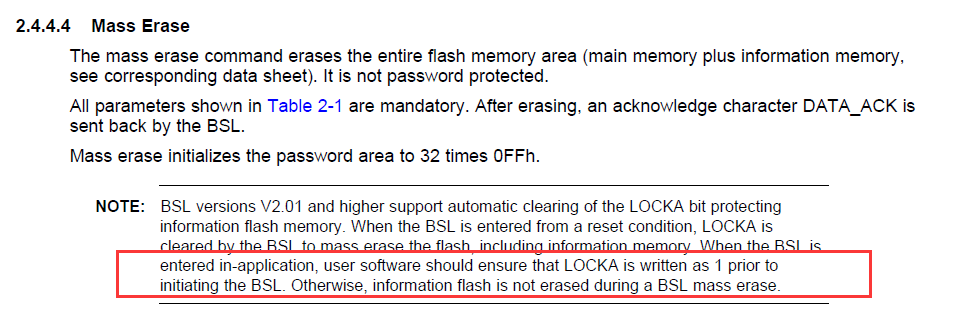
    SLAU319 on BSL is not quite so clear:

    NOTE: BSL versions V2.01 and higher support automatic clearing of the LOCKA bit protecting
    information flash memory. When the BSL is entered from a reset condition, LOCKA is
    cleared by the BSL to mass erase the flash, including information memory. When the BSL is
    entered in-application, user software should ensure that LOCKA is written as 1 prior to
    initiating the BSL. Otherwise, information flash is not erased during a BSL mass erase.

    The question is what the situation actually is in BSL, specifically for the the G2553.

    Thanks very much.

    Edit:  Ok, I found what I think is definitive info on this.  It's in the "Bible" - SLAU144.  Section 7.2.1 on Segment A is clear in saying that setting LOCKA protects all of information memory, not just INFOA, from a mass erase.  This is confirmed in Table 7-1 Erase Modes and in section 7.4.3 FCTL3 (in the LOCKA entry).

  • George,

    I believe you are correct here. There was some confusion on my side when looking at the BSL code specifically. The User Guide clarification is the answer to this question.
  • Jace H said:
    George,

    I believe you are correct here. There was some confusion on my side when looking at the BSL code specifically. The User Guide clarification is the answer to this question.

    Well actually, if the BSL code not only does the built-in mass erase command but also erases B,C and D segments individually if LOCKA is set, then specifically for BSL purposes LOCKA really would only protect INFOA.  I don't have access to the G2553 BSL source, so I'll depend on you to see if it does that.  I could do an actual test with BSLDEMO, but don't have my BSL rig set up right now.  Let me know if you need me to do that.

  • George,

    If you have the time and are offering, this should be an easy test. I will not be able to do the testing myself until after the holidays due to end of year activities.

    You would think this should be easy to determine from documentation, but with the wording of how the LOCKA bit is described versus how the BSL responds, it has left a doubt for me.

    For the test, you do need to make sure its SW entry though, as any other entry will clear the LOCKA bit.
  • Jace H said:
    George,

    If you have the time and are offering, this should be an easy test. I will not be able to do the testing myself until after the holidays due to end of year activities.

    You would think this should be easy to determine from documentation, but with the wording of how the LOCKA bit is described versus how the BSL responds, it has left a doubt for me.

    For the test, you do need to make sure its SW entry though, as any other entry will clear the LOCKA bit.

    I have very short special boot code that fits within INFOA between the calibration items, with the reset vector pointing to it.  It will jump into BSL if it detects that the Rx pin is connected to the USB adapter.  I think the best place to jump to would be 0x0C0C, which is right after the instruction to toggle LOCKA.  Assuming it boots up with LOCKA set, it will just stay that way.  And I'll put some stuff in INFOB, C and D.  Then I think a single mass erase instruction from BSLDEMO, then go back and read in the INFO memory through my launchpad to see if it was erased.  Does that sound right?  I should be able to get this done sometime this week.

  • George,

    That sounds like it could work. You can also just enter BSL space via SW by doing the following instruction:

    __disable_interrupt();
    ((void (*)())0x1000)();

    This will load address 0x1000 to the program counter. Address 0x1000 contains a jump instruction tot he start of the BSL.

  • Hi Georg, Hi Jace,

    first of all: thanks a lot for thorough consideration regarding this topic. Since the G2553 is quite old device using old version of BSL programming tools, I needed sometime to have the test being ready.

    Here is my step:

    1. I built a blink application that also writes to information memory A - D randomly, and after blinking 10 times, I jumped to the BSL application. In SLAU319, it is written that cold start is 0C00h and warm start 0C02h. Cold start will unlock the LOCKA, and caused information memory erased. if you look into memory browser in CCS, the 0C02h points to 0C1Eh. I chose this 0C1Eh as the jump address for my blink application.

    2. I used the BSL rocket (or CP2102 should work as well), and provide the command and password using hTerm. I connect the Vcc, Gnd, TX and RX. No BSL entry sequence is applied.

    3. The command I send to BSL: 0x80 then BSL reply 0x90; then send the default password, BSL reply with 0x90, then I send the mass erase, BSL reply with 0x90.

    4. I disconnected the BSL connection, and put the JTAG, launch the debug session to read the information memory, nothing is erased.

    That means, what I got from my experiment is that having LOCKA set, will skip also erasing the information memory B, C, and D. Let me know if this result is the same with what you get later :)

  • I agree with Fatmawati_Santosa's results.  I set my software BSL entry to jump to 0x0C0C, which is immediately after the BSL instruction to toggle INFOA.  Since INFOA is set on powerup/reset, skipping the toggle leaves it that way, but does a Cold Start otherwise.  With that entry method, a mass erase leaves *ALL* of INFO memory protected, and erases only MAIN memory.  On the PC side I used BSLDEMO2.

    I did have a problem though with BSL not behaving right, but figured out that the BSL toggle instruction not only toggles LOCKA but also clears the remaining bits of FCTL3, two of which are set on boot.  When I inserted an instruction to clear the other bits of FCTL3 before jumping into BSL, everything worked ok.

    So I think this settles the issue.  I'm not sure how useful this behavior is, but at least it's now clear.

  • Hi Georg,

    thank you very much for your support in checking this behavior, I really appreciate it!

    I will put this information in the user's guide as a note. Since it is the ROM BSL, we could not change the behavior of coldstart and warmstart, we get the conclusion that by coldstart, mass erase erases all parts memory, and warmstart only erases the main memory.

    For the second behavior, it is quite often found in application that calling BSL. It is suggested to clear the registers that been used in your application before jump to the BSL. We put this information under chapter 3.8.1 for SLAU319.

  • Table 22 in SLAU319 has some specific pre-call requirements before jumping into BSL v2.02 and v2.03, specifically including the G2553.  They are in the section "Preparation for software call" and in footnote 2.  Chapter 3.8.1 appears to apply only to F5xx and F6xx parts, and I don't know if anything discussed in this thread applies to them.

**Attention** This is a public forum