This thread has been locked.

If you have a related question, please click the "Ask a related question" button in the top right corner. The newly created question will be automatically linked to this question.

MSP430F5329: How do you send a NAK in I2C SMBus Protocol

Part Number: MSP430F5329
Other Parts Discussed in Thread: MSP-EXP430FR2433, MSPDRIVERLIB, MSP430FR2433, MSP430WARE

I have been writing a SMBus slave for Read Word, Write Word, and Block Read protocol with and without PEC, using the MSP430F5329.

I have been using the Python SMBUS libraries on the Raspberry Pi to test the code. I have gotten the Read word with PEC and Without PEC. 

I can not get the Read Block to work, and I know the bytes I am sending are right. Documentation is nonexistant. So I am looking for something else. 

In the process of looking at the SMBus protocol more closely in both the read word and block read,  the last data byte sent by the slave is NAKed by the master, then the master sends a Stop. I had not noticed it before.

My code lets me know every time an I2C interrupt is generated and logs the type of interrupt. I have never seen a NAK interrupt come through. So now I am very suspicious of the Raspberry Pi code. 

I figured I might as well use another MSP430 chip as my I2C Master and picked up the MSP-EXP430FR2433. I was looking at the library functions in the MSPDRIVERLIB: DriverLib for MSP430 devices and can not figure out a way to send a NAK after a the last byte is received, as the SMBus specification requires. 

For example Figure 31 in System Management Bus (SMBus) Specification Version 3.0 

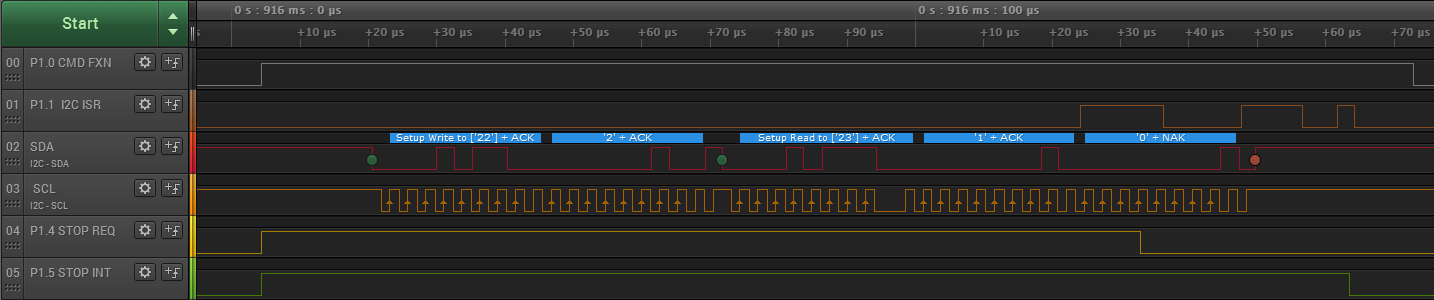
<Master Start> <Master Address> <Master Wr> <Slave ACK> <Master Command Code> <Slave ACK> <Master Restart> <Master Address> <Master R> <Slave ACK>
<Slave Data byte Low> <Master Ack> <Slave Data byte High> <Master NAK> <Master Stop>


What am I missing?

How do I send the Master NAK in response to the Slave sending the Data byte High? It seems to be ACKed automatically.  

Kip


  • Hi Kip,

    I can't speak for what you are seeing with the RPi Python libraries, but I can give you some clarity on the I2C peripheral operation on the MSP430FR2433 and MSP430F5329. The specific I2C bus operating mode you are using the MSP430FR2433 in is the I2C master receiver mode. This is described in section 23.3.5.2.2 of the MSP430FR2xx_4xx User's Guide (www.ti.com/.../slau445g.pdf). From the guide: "A STOP condition is either generated by the automatic STOP generation or by setting the UCTXSTP bit. The next byte received from the slave is followed by a NACK and a STOP condition. This NACK occurs immediately if the eUSCI_B module is currently waiting for UCBxRXBUF to be read."

    Basically, the eUSCI_B I2C peripheral on the MSP430FR2433 will generate the NACK automatically if UCTXSTP is set during reception of the last byte in your transaction with the slave. Alternatively, if you are using the eUSCI_B automatic STOP generation, the NACK will also happen automatically and you don't have to do anything at all. In fact, that is how the eusci_b_i2c_ex2_masterRxSingle DriverLib code example works. The automatic STOP generation is handy if you know exactly how many bytes you want to receive on the master side before you start the transaction.

    If you are using the DriverLib for a multi-byte receive operation, and are not using automatic STOP generation, then you will want to use these functions for the transaction:

    extern void EUSCI_B_I2C_masterReceiveStart(uint16_t baseAddress);
    extern uint8_t EUSCI_B_I2C_masterReceiveMultiByteNext(uint16_t baseAddress);
    extern uint8_t EUSCI_B_I2C_masterReceiveMultiByteFinish(uint16_t baseAddress);

    The calling sequence is a little bit tricky. You will call EUSCI_B_I2C_masterReceiveStart() to get things moving. Then, you will wait for an RX interrupt flag to call EUSCI_B_I2C_masterReceiveMultiByteNext() to receive all of the bytes in the transaction, EXCEPT for the last byte. For the last byte, you do not wait for an RX interrupt. Instead, you call EUSCI_B_I2C_masterReceiveMultiByteFinish() immediately. This will set UCTXSTP for you, wait for the RX receive to finish, and return the last byte at the end. By doing this, the NACK occurs followed by the stop condition. As an example, if you wanted to read 4 bytes from the slave device you would do the following:

    uint8_t data[4];

    EUSCI_B_I2C_masterReceiveStart(EUSCI_ADDRESS);
    while(!(EUSCI_B_I2C_getInterruptStatus(EUSCI_ADDRESS, EUSCI_B_I2C_RECEIVE_INTERRUPT0)));
    data[0] = EUSCI_B_I2C_masterReceiveMultiByteNext(EUSCI_ADDRESS);
    while(!(EUSCI_B_I2C_getInterruptStatus(EUSCI_ADDRESS, EUSCI_B_I2C_RECEIVE_INTERRUPT0)));
    data[1] = EUSCI_B_I2C_masterReceiveMultiByteNext(EUSCI_ADDRESS);
    while(!(EUSCI_B_I2C_getInterruptStatus(EUSCI_ADDRESS, EUSCI_B_I2C_RECEIVE_INTERRUPT0)));
    data[2] = EUSCI_B_I2C_masterReceiveMultiByteNext(EUSCI_ADDRESS);
    data[3] = EUSCI_B_I2C_masterReceiveMultiByteFinish(EUSCI_ADDRESS);

    Note that for the last byte, we don't poll the RX interrupt flag; rather, we go directly to the 'finish' fxn call. This can all be rolled into an interrupt handler as well- this is just a simple polling example to show the basic concept.

    Let me know if you have further questions.

    Regards,
    Walter
  • I have to think about this a bit. On the block transfer the first byte read is the length of the data to follow, not counting the PEC. 

    So for the master, I have to read one byte, than use that input for the number of bytes to read (and if there is a PEC add one more to the number of bytes to read) and when it gets to the last byte it will send the NAK and then the Stop.

    O.K. so next step is to implement it. :)  Something for Monday. 

    Thanks,

    Kip

  • I think I am close to understanding this.  I am confused about a couple of things.

    To initialize:

    EUSCI_B_initMasterParam MP;
    
    void init_I2C_master_for_host(void)
    {
      MP.selectClockSource = EUSCI_B_CLOCKSOURCE_SMCLK;
      MP.i2cClk = 16000000;
      MP.dataRate = EUSCI_B_I2C_SET_DATA_RATE_100KBPS;
      MP.byteCounterThreshold = 255;
      MP.autoSTOPGeneration = EUSCI_B_I2C_NO_AUTO_STOP;
     
      // The values passed are defined in the I2C_master_for_host.h file
    
      EUSCI_B_I2C_initMaster(I2C_HOST_BASE_ADDRESS,&MP);
      EUSCI_B_I2C_set_SlaveAddress(I2C_HOST_BASE_ADDRESS,I2C_HOST_SLAVE_ADDRESS);
      EUSCI_B_I2C_setMode(I2C_HOST_BASE_ADDRESS, USCI_B_I2C_TRANSMIT_MODE);  //  Is this right? 
      EUSCI_B_I2C_enable(I2C_HOST_BASE_ADDRESS);
      EUSCI_B_I2C_enableInterrupt(I2C_HOST_BASE_ADDRESS,0xFF); // All interrupts
    }

    First question: I do not understand setMode.

    Here is what the documentation says MSP430FR2xx_4xx_DriverLib_Users_Guide:

    void EUSCI B I2C setMode ( uint16 t baseAddress, uint8 t mode )
    Sets the mode of the I2C device.
    When the receive parameter is set to EUSCI B I2C TRANSMIT MODE, the address will indicate
    that the I2C module is in receive mode; otherwise, the I2C module is in send mode.
    Parameters

    baseAddress is the base address of the USCI I2C module.
    mode Mode for the EUSCI B I2C module Valid values are:
    EUSCI B I2C TRANSMIT MODE [Default]
    EUSCI B I2C RECEIVE MODE

    Modified bits are UCTR of UCBxCTLW0 register.
    Returns
    None
     
    Is that a typo? When the receive is Transmit mode it is in Receive Mode? What???


    Moving on...  So now it is initialized:

    I want to send a command: normally I would want a <Start><Slave Address Write> <Command> <Start> <Slave Address Read> <Number Bytes (3)> <Byte 1> ... <Byte 3><NAK><Stop>
    Bold is the host sending, not bold is the slave sending

    uint8_t data[4];

    // I need to make sure the setMode is Transmit to start?

    EUSCI_B_I2C_masterSendMultiByteStart(EUSCI_ADDRESS,Command);

    // Do I change the setMode to Receive here before the start? 

    // I understand this part mostly have a couple of questions:

    EUSCI_B_I2C_masterReceiveStart(EUSCI_ADDRESS); // This generates the second start or restart
    while(!(EUSCI_B_I2C_getInterruptStatus(EUSCI_ADDRESS, EUSCI_B_I2C_RECEIVE_INTERRUPT0)));
    data[0] = EUSCI_B_I2C_masterReceiveMultiByteNext(EUSCI_ADDRESS);  // Number of bytes = 3
    while(!(EUSCI_B_I2C_getInterruptStatus(EUSCI_ADDRESS, EUSCI_B_I2C_RECEIVE_INTERRUPT0)));
    data[1] = EUSCI_B_I2C_masterReceiveMultiByteNext(EUSCI_ADDRESS); // Byte 1
    while(!(EUSCI_B_I2C_getInterruptStatus(EUSCI_ADDRESS, EUSCI_B_I2C_RECEIVE_INTERRUPT0)));
    data[2] = EUSCI_B_I2C_masterReceiveMultiByteNext(EUSCI_ADDRESS); // Byte 2
    data[3] = EUSCI_B_I2C_masterReceiveMultiByteFinish(EUSCI_ADDRESS); // Byte 3 

    I am doing this all interrupt driven and I have a state machine.

    Does the last command poll until the data Byte 3 is received? I cannot poll in a ISR. I can see all interrupts. Is there a better way to do this?

    Maybe when the receive interrupt for Byte 2 fires, I should set the UCTXSTP? Then wait for the Receive interrupt to get data[3]?

    I do not think there are any other interrupts that should fire except the two Start interrupts, and one or two  transmit Interrupts right? 


    One more question on the other side. When this ends the Slave will get a NAK interrupt and a Stop interrupt? or just one of them? (If one, which one?)

    Thanks,
    Kip
     

  • Hi Kip,

    Kipton Moravec said:
    Is that a typo? When the receive is Transmit mode it is in Receive Mode? What???

    Yes, this is a misprint.  I have notified the developer and this will be fixed in the next DriverLib / MSP430Ware release.  The correct comment should read: "When the mode parameter is set to EUSCI_B_I2C_TRANSMIT_MODE, the address will indicate that the I2C module is in send mode; otherwise, the I2C module is in receive mode."

    With regard to the rest of your questions:

    - Before calling EUSCI_B_I2C_masterSendMultiByteStart() you do want to set the mode to transmitter using EUSCI_B_I2C_setMode(I2C_0_BASE, EUSCI_B_I2C_TRANSMIT_MODE).

    - Interestingly enough, you do not need to change the mode to receiver when sending out the repeated start; this is done from within EUSCI_B_I2C_masterReceiveStart(I2C_0_BASE).

    - You are correct, you don't want to be polling in an ISR.  For the ISR approach, you can use EUSCI_B_I2C_masterReceiveMultiByteStop() instead of EUSCI_B_I2C_masterReceiveMultiByteFinish().  This sets the stop condition generation bit.  The tricky part with this is getting the timing to work out.  That bit needs to be set before the last byte is clocked in for the nack to get generated correctly by the master.  This is the area of critical timing.  The byte counter feature is handy if you know the # of bytes to receive, because it will generate the stop and nack automatically.

    - In master receiver mode, you WILL get a stop interrupt when the stop condition goes through.  You will not get the NACK interrupt from the master-generated NACK.  You only get this if the slave NACK's.

    Walter

  • Here is a code snipped I implemented on an MSP-EXP430FR2433 LaunchPad with a dummy host to mimic your use-case with a 1-byte read-out from the slave.

    #include "msp430.h"
    #include "driverlib.h"
    
    #define DCOFREQ 8000000
    
    #define I2C_0_BASE (EUSCI_B0_BASE)
    #define I2C_RECEIVE_BUFFER_SIZE (32)
    
    uint8_t I2C_0_rxBuffer[I2C_RECEIVE_BUFFER_SIZE];
    int8_t I2C_0_rxBytesRemaining = 0;
    int8_t I2C_0_rxCnt = 0;
    
    void setup(void)
    {
        EUSCI_B_I2C_initMasterParam I2C_0;
    
        // SMCLK = MCLK = DCO = 4MHz
        // ACL = 32kHz
        CS_initClockSignal(CS_FLLREF, CS_REFOCLK_SELECT, CS_CLOCK_DIVIDER_1);
        CS_initClockSignal(CS_ACLK, CS_REFOCLK_SELECT, CS_CLOCK_DIVIDER_1);
        CS_initClockSignal(CS_MCLK, CS_DCOCLKDIV_SELECT, CS_CLOCK_DIVIDER_1);
        CS_initClockSignal(CS_SMCLK, CS_DCOCLKDIV_SELECT, CS_CLOCK_DIVIDER_1);
        CS_initFLL((DCOFREQ/1000), DCOFREQ/32768);
        CS_clearAllOscFlagsWithTimeout(1000);
    
        // I2C port mux selection
        P1OUT = 0;
        P1DIR |= BIT0 | BIT1 | BIT4 | BIT5 | BIT6;
        P1SEL0 |= BIT2 | BIT3;
        PM5CTL0 &= ~LOCKLPM5;
    
        // I2C Setup
        I2C_0.selectClockSource = EUSCI_B_I2C_CLOCKSOURCE_SMCLK;
        I2C_0.i2cClk = DCOFREQ;
        I2C_0.dataRate = EUSCI_B_I2C_SET_DATA_RATE_400KBPS;
        I2C_0.byteCounterThreshold = 0;
        I2C_0.autoSTOPGeneration = EUSCI_B_I2C_NO_AUTO_STOP;
    
        EUSCI_B_I2C_disable(I2C_0_BASE);
        EUSCI_B_I2C_initMaster(I2C_0_BASE, &I2C_0);
        EUSCI_B_I2C_enable(I2C_0_BASE);
    
        __delay_cycles(8000000);
    }
    
    uint8_t I2C_0_readCmd(uint8_t slave, uint8_t cmd)
    {
        P1OUT |= BIT0 | BIT4 | BIT5 | BIT6;
    
        // Set slave address and wait for bus
        EUSCI_B_I2C_setSlaveAddress(I2C_0_BASE, slave);
        EUSCI_B_I2C_clearInterrupt(I2C_0_BASE,
                    EUSCI_B_I2C_RECEIVE_INTERRUPT0 |\
                    EUSCI_B_I2C_TRANSMIT_INTERRUPT0 |\
                    EUSCI_B_I2C_STOP_INTERRUPT );
        EUSCI_B_I2C_enableInterrupt(I2C_0_BASE,
                    EUSCI_B_I2C_RECEIVE_INTERRUPT0 |\
                    EUSCI_B_I2C_STOP_INTERRUPT );
        I2C_0_rxBytesRemaining = 0;
    
        // Write command to slave
        EUSCI_B_I2C_setMode(I2C_0_BASE, EUSCI_B_I2C_TRANSMIT_MODE);
        EUSCI_B_I2C_masterSendMultiByteStart(I2C_0_BASE, cmd);
        while(!(EUSCI_B_I2C_getInterruptStatus(I2C_0_BASE, EUSCI_B_I2C_TRANSMIT_INTERRUPT0)))
        {
            if (EUSCI_B_I2C_getInterruptStatus(I2C_0_BASE, EUSCI_B_I2C_NAK_INTERRUPT))
            {
    
                return 0;
            }
        }
    
        // Read response from slave
        EUSCI_B_I2C_masterReceiveStart(I2C_0_BASE);
        while (EUSCI_B_I2C_isBusBusy(I2C_0_BASE));
        EUSCI_B_I2C_disableInterrupt(I2C_0_BASE,
                    EUSCI_B_I2C_RECEIVE_INTERRUPT0 |\
                    EUSCI_B_I2C_STOP_INTERRUPT );
    
        P1OUT &= ~BIT0;
        return I2C_0_rxCnt;
    }
    
    void run(void)
    {
        I2C_0_readCmd(0x0B, 0x02);
        __no_operation();
        __delay_cycles(1000000);
    }
    
    void main(void)
    {
        WDTCTL = WDTPW | WDTHOLD;
        __enable_interrupt();
        setup();
        while(1)
        {
            run();
        }
    }
    
    #pragma vector=USCI_B0_VECTOR
    __interrupt void I2C_0_ISR(void)
    {
        uint8_t data;
    
        P1OUT |= BIT1;
        switch(__even_in_range(UCB0IV,0x1E))
        {
            case 0x00: break;       // Vector 0: No interrupts break;
            case 0x02: break;       // Vector 2: ALIFG break;
            case 0x04: break;       // Vector 4: NACKIFG break;
            case 0x06: break;       // Vector 6: STT IFG break;
            case 0x08:
                P1OUT &= ~BIT5;
                break;       // Vector 8: STPIFG break;
            case 0x0a: break;       // Vector 10: RXIFG3 break;
            case 0x0c: break;       // Vector 14: TXIFG3 break;
            case 0x0e: break;       // Vector 16: RXIFG2 break;
            case 0x10: break;       // Vector 18: TXIFG2 break;
            case 0x12: break;       // Vector 20: RXIFG1 break;
            case 0x14: break;       // Vector 22: TXIFG1 break;
            case 0x16:              // Vector 24: RXIFG0 break;
                // Receive byte
                data = EUSCI_B_I2C_masterReceiveMultiByteNext(I2C_0_BASE);
    
                // If this is the first byte (RX Length Invalid), then save the length to read
                // and reset the receive counter to 0
                if (I2C_0_rxBytesRemaining == 0x00)
                {
                    I2C_0_rxBytesRemaining = data;
                    if (I2C_0_rxBytesRemaining > I2C_RECEIVE_BUFFER_SIZE)
                    {
                        I2C_0_rxBytesRemaining = I2C_RECEIVE_BUFFER_SIZE;
                    }
                    I2C_0_rxCnt = 0;
                }
    
                // If this is not the first byte, append the response to the RX
                // buffer
                else
                {
                    I2C_0_rxBuffer[I2C_0_rxCnt++] = data;
                    I2C_0_rxBytesRemaining--;
                }
    
                // Send NACK and STOP on last byte coming in
                if (I2C_0_rxBytesRemaining == 1)
                {
                    P1OUT &= ~BIT4;
                    EUSCI_B_I2C_masterReceiveMultiByteStop(I2C_0_BASE);
                }
                break;
            case 0x18: break;       // Vector 26: TXIFG0 break;
            case 0x1a: break;       // Vector 28: BCNTIFG break;
            case 0x1c: break;       // Vector 30: clock low timeout break;
            case 0x1e: break;       // Vector 32: 9th bit break;
            default: break;
        }
    
        P1OUT &= ~BIT1;
    }
    

    This gives the following logic trace:

  • Note that the code above doesn't include much of anything in the way of error handling, timeouts, or a comprehensive state machine. The goal is to show how to implement your SMBus use-case.

    Regards,
    Walter
  • Walter, I have a question about your code as I was adapting it for my use.

    in the subroutine I2C_0_readCmd(...)
    You clear
    EUSCI_B_I2C_clearInterrupt(I2C_0_BASE,
    EUSCI_B_I2C_RECEIVE_INTERRUPT0 |\
    EUSCI_B_I2C_TRANSMIT_INTERRUPT0 |\
    EUSCI_B_I2C_STOP_INTERRUPT );

    Then you enable:

    EUSCI_B_I2C_enableInterrupt(I2C_0_BASE,
    EUSCI_B_I2C_RECEIVE_INTERRUPT0 |\
    EUSCI_B_I2C_STOP_INTERRUPT );

    But you test on:
    while(!(EUSCI_B_I2C_getInterruptStatus(I2C_0_BASE, EUSCI_B_I2C_TRANSMIT_INTERRUPT0)))

    How does that work? Is there an enable interrupt in one of those library functions?

    Kip

**Attention** This is a public forum