This thread has been locked.

If you have a related question, please click the "Ask a related question" button in the top right corner. The newly created question will be automatically linked to this question.

MSP430F6736A: RTC_C not ticking over on battery backup

Part Number: MSP430F6736A
Other Parts Discussed in Thread: MSP430F6779, MSP-TS430PZ100B, , MSP-FET, MSP430F6736

Hi anyone

I have a coin battery back up to the MCU via AUXCC3.
(The intention behind the battery backup is purely to keep the RTC & Backup RAM, powered..it is not to power the MSP in any of its modes.)

The board gets its normal power from another (failable) source.

When the main power drops, the battery kicks in.the RTC is supposed to tick over....except it doesnt.
I checked the 32k crystal via a scope probe on the one leg...that kicked in nicely when the battery kicked in.

The backup ram retained its data.
But the RTC...very strange...it retained the time that the power went down & then once power came back, it resumed from that time. So it means it never ticked over.
There is no indication that anything was amiss....SYSRSTIV, on startup, returns 2h indicating a brownout which is fine.
My setting for AUXVCC3...AUX3CHCTL = AUXCHKEY | AUXCHV_1 | AUXCHC_1 | AUXCHEN; 

Any possible reason for this?

What can i do to determine more about what is happening?

thanks in advance.

  • Hi moshe,

    Can you please try the MSP430F6779_AUX_[05/06].c examples from the TIDM-AUXMODULE software resources and comment on any differences? Also make sure that the proper decoupling capacitors are installed. e2e.ti.com/.../

    Regards,
    Ryan
  • Hi Ryan

    Thanks for your response.

    Just some initial points:

    i'm using a F6736A not a F6779;
    i'm not going into LPM3.5 (or any mode) i'm simply looking at the situation where main power has gone & the RTC_C is now being powered by the battery (when main power is ON, AUXCC3 is powering the RTC_C).

    So having said that...i looked at the 06.c & decided to try a situation whereby the RTC_C is powered EXCLUSIVELY by the battery.
    To do that, in my setup lines (which are the 1st few lines in main),  i commented out my line AUX3CHCTL = AUXCHKEY | AUXCHV_1 | AUXCHC_1 | AUXCHEN;
    and replaced it with just AUX3CHCTL = AUXCHKEY;  which is really resetting it to what it was when control entered my main().

    On the hardware side i have the following:

    My scope probe is on XTAL1 IN (pin24).
    Bench PSU to the battery is set at 3.3V.
    Ammeter on +ve wire sitting between the bench PSU and the battery holder.

    So the results:

    With the MCU running off normal main power, the backup mem+RTC_C are running (current drawn on bench PSU 1.2uA & scope  shows the crystal waveform).
    I check that the RTC_C is running via a comms program i wrote that communicates with my firmware via eUSCI and i see that RTC_C is ticking over correctly.
    The waveform DOESNT change in any manner when power is removed.
    I wait 30secs and restore main power & check RTC_C again....it has only progressed the 2 secs or so for my to disconnect main, reconnect main, & click my 'Get Time' button....ie when main power resumes, the RTC_C resumes with the SAME values it LAST had when main power was removed.

    This tells me that during the time main power was removed the RTC_C did NOT lose its contents but it also did NOT increment the time!

    The ONLY discernible difference between this test and the normal situation whereby RTC_C is powered by AUXCC3 is in the following:

    When AUXCC3 is DISabled (this test above):

    The 32K crystal waveform does NOT move when main power is removed and restored.
    And the power drawn remains constant at 1.2uA.

    When AUXCC3 is ENabled (the normal situation):

    The 32K waveform dips momentarily in the crossover from AUXVCC3 to battery.
    The power drawn under main power is 0A and when main is removed, the power drawn goes to 1.2uA.

    So...next step?

  • Hi moshe,

    If RTC data is retained but does not increment then it would seem like XT1 is not oscillating properly in the AUXVCC3 VBAK case. However, you had mentioned that it was operating as expected with the battery. What is the measured current under battery power? Can you provide schematics and a simple code example that demonstrates the issue?

    Regards,
    Ryan
  • Hi Ryan

    The waveform SHAPE (nice sine curve) via battery or via AuxVcc3 is the same..the magnitude IS slightly different.

    i set the bench PSU at 3.3V

    Given the scenario where AuxVcc3 is DISsabled:

    The waveform max/min is 2.60V &  2.39V, current drawn from PSU is 1.0uA REGARDLESS of whether main power is applied or not.

    And When the AuxVcc3 is ENabled:

    With main power powering the board, the waveform max/min becomes 2.66V & 2.45V, current drawn is 0uA.

    When main power is removed the waveform max/min is 2.60V &  2.39V, current drawn is 1.0uA

    Code...

    AUX3CHCTL = AUXCHKEY | AUXCHV_1 | AUXCHC_1 | AUXCHEN;  // Charger for AUX3...Vcc, 5K resistor, enable

    RTCCTL0_H = RTCKEY_H;                      // Unlock RTC_C module

    RTCCTL0_L |= RTCRDYIE;   //  read ready interrupt (every sec)

    RTCCTL1 = 0;

    RTCCTL1 = 0x00 | RTCHOLD | RTCMODE;  // RTC enable binary mode ~RTCBCD, RTC hold, calendar mode

    RTCCTL1 &= ~RTCHOLD;      // Start RTC calendar mode

    RTCCTL0_H = 0;              // Lock RTC_C module

    there is no code i can present to demonstrate that the RTC is not ticking over..it is an observation (which is how i discovered this unexpected problem).

    Read the clock, Remove power, Wait a minute, Read the clock.

    For schematics: 


    cheers

    moshe

  • What is the CPU frequency and has PMMCOREV been stepped up correctly?  Have you considered testing with a dedicated power supply at AUXVCC3 instead of a battery? Humor me by unlocking the PMM registers (PMMCTL0_H = PMMPW_H;) before modifying AUX3CHCTL and confirm through the debugger that all bits are set correctly afterwards.  I think I have everything necessary to try and re-create this issue.

    Regards,
    Ryan

  • Hi Ryan

    Q: What is the CPU frequency?
    A: I believe its 16MHz or is it 8MHz?

    This is how it is set up (XT1 is the FLLREF CLK of 32768).

    UCSCTL0 = 0; // Set lowest possible DCOx, MODx
    UCSCTL1 = DCORSEL_5; // the permissible range for this is 6MHz-23.7MHz see fig10 datasheet
    UCSCTL2 = FLLD_1 | 255; //sets FLLN to 255 so (N+1)=256, FLLD = 1 so D = 2....
    UCSCTL3 = SELREF_0 | FLLREFDIV_0; //its the default
    UCSCTL4 = SELM__DCOCLK | SELS__DCOCLK | SELA__XT1CLK; //MCLK & SMCLK come from DCOCLKDIV (8MHz), 32KHz ACLK
    UCSCTL5 |= DIVS__1; // this effectevly sets UCSCTL5 to 0 which means no division of any of the ACLK, MCLK, SMCLK clks

    According to the user guide fDCOCLKDIV = MCLK = (N+1)x32768 = (255+1)x32768 which makes it 8MHz
    fDCOCLK = fDCOCLKDIV*D = 16MHz

    I noticed that PMMCOREV was kept at the default 0 so i added this line BEFORE setting the DCO.....but it made no difference
    PMMCTL0 = 0xa503; // sheesh...forgot to set it to Vcore3...see fig5-1 in datasheet

    I also set this line immediately after the PMM line
    AUX3CHCTL = AUXCHKEY; //DISABLE charger so only battery is used - testing for TI

    Q: Have you considered testing with a dedicated power supply at AUXVCC3
    A: Since i discovered the issue i have ONLY been testing with the bench PSU at AUXVCC3.

    Regarding hunouring you...yes i have by adding the line to get it to coreV3
    And i checked that AUX3HCTL remained set to what i wanted by executing PMMCTL0_H = 0; and checking AUX3HCTL.

    So next thing to try?

    cheers
    Moshe

  • Did you disable the FLL control loop before changing the UCSCTL registers (__bis_SR_register(SCG0);)? This configuration is for a DCO approximately equal to 8.389 MHz which would require a PMMCOREv level of 1, transitioning appropriately requires a sequence as demonstrated in the msp430f665x_ucs_03.c SetVCoreUp function. I will try to replicate this issue next week and report my findings.

    Regards,
    Ryan
  • Hi Ryan
    Yes, the FLL control loop is disabled before any of the above & enabled after the above (after the UCSCTL5 assignment).

    My understanding is that due to the line
    UCSCTL4 = SELM__DCOCLK | SELS__DCOCLK | SELA__XT1CLK;
    MCLK is at fDCO which in this case is 16MHz.
    (i was incorrect in saying in the previous post that MCLK is from fDCOCLKDIV)

    I understand that correct transitioning is required...
    and i have just implemented the code based on msp430f665x_ucs_03.c SetVCoreUp
    but i dont see how the PMM function would have any bearing on what happens to the RTC when it is operating on AUXVCC3 via a bench PSU & main power is removed.

    As it is...i still have the problem of RTC not ticking over on main power removal.

    regards
    moshe

  • Hi moshe,

    The following code operated properly using the MSP-TS430PZ100B with a 32 kHz external crystal and load capacitors.  With JP4, JP11, and JP12 unpopulated to remove DVCC, AUXVCC1, and AUXVCC2, respectively, RTCSEC and RTCTIM0 still incremented from AUXVCC3 power.

    #include <msp430.h>
    
    void SetVcoreUp (unsigned int level);
    
    void main(void)
    {
        WDTCTL = WDTPW | WDTHOLD;               // Stop WTD
    
        // Setup P11.5 RTCCLK
        P9DIR |= BIT0;            // RTCCLK set out to pins
        P9SEL |=BIT0;
    
        SetVcoreUp (0x01);
        SetVcoreUp (0x02);
    
        //Enable Charger
        AUX3CHCTL = AUXCHKEY + AUXCHC_1 + AUXCHV_1 + AUXCHEN;
    
    //    // Initialize LFXT1
        UCSCTL6 &= ~(XT1OFF);                   // Enable XT1
    //    UCSCTL6 |= XCAP_3;                      // Internal load cap
        // Loop until XT1, XT2 & DCO fault flag is cleared
    
        __bis_SR_register(SCG0);                  // Disable the FLL control loop
        UCSCTL0 = 0x0000;                         // Set lowest possible DCOx, MODx
        UCSCTL1 = DCORSEL_5;                      // Select DCO range 24MHz operation
        UCSCTL2 = FLLD_1 + 487;                   // Set DCO Multiplier for 16MHz
                                                  // (N + 1) * FLLRef = Fdco
                                                  // (487 + 1) * 32768 = 16MHz
                                                  // Set FLL Div = fDCOCLK/2
        __bic_SR_register(SCG0);                  // Enable the FLL control loop
    
        // Worst-case settling time for the DCO when the DCO range bits have been
        // changed is n x 32 x 32 x f_MCLK / f_FLL_reference. See UCS chapter in 5xx
        // UG for optimization.
        // 32 x 32 x 16 MHz / 32,768 Hz = 500000 = MCLK cycles for DCO to settle
        __delay_cycles(500000);
    
        do
        {
            UCSCTL7 &= ~(XT2OFFG | XT1LFOFFG | DCOFFG);
            // Clear XT2,XT1,DCO fault flags
           SFRIFG1 &= ~OFIFG;                  // Clear fault flags
        } while (SFRIFG1 & OFIFG);              // Test oscillator fault flag
    
        // Start RTC calendar mode
        RTCCTL0_H = RTCKEY_H;                   // Unlock RTC_C module
        RTCCTL0_L |=  RTCRDYIE; //              // Enable RTC time event,
        RTCCTL1 |= RTCBCD;
         RTCCTL13 &=  ~(RTCCALF_3);  //Clear all RTCCALF bits since they may have previous RTCCALF value.
        RTCCTL13 |=  RTCCALF_1;     //512 Hz RTC output
        RTCCTL1 &= ~(RTCHOLD);  //In this case, RTCHOLD may be set with POR.  However, it does not
                                //get set in the case VDSYS goes off, but it does get set when it comes
                                //back.  Therefore, it should get reset to enable operation.
        RTCCTL0_H = 0;
    
        __bis_SR_register(GIE);
        while(1) __no_operation();
    }
    
    // RTC Interrupt Service Routine
    #pragma vector=RTC_VECTOR
    __interrupt void rtc_isr(void)
    {
        switch (__even_in_range(RTCIV, 16))
        {
            case RTCIV_NONE:                    // No interrupts
                break;
            case RTCIV_RTCOFIFG:                // RTCOFIFG
                break;
            case RTCIV_RTCRDYIFG:               // RTCRDYIFG
                __no_operation();
                break;
            case RTCIV_RTCTEVIFG:               // RTCEVIFG
                __no_operation();
                break;
            case RTCIV_RTCAIFG:                 // RTCAIFG
                __no_operation();
                break;
            case RTCIV_RT0PSIFG:                // RT0PSIFG
                break;
            case RTCIV_RT1PSIFG:                // RT1PSIFG
                break;
    //        case 14: break;                   // Reserved
            case 16: break;                     // Reserved
            default: break;
        }
    }
    
    void SetVcoreUp (unsigned int level)
    {
      // Open PMM registers for write
      PMMCTL0_H = PMMPW_H;
      // Set SVS/SVM high side new level
      SVSMHCTL = SVSHE + SVSHRVL0 * level + SVMHE + SVSMHRRL0 * level;
      // Set SVM low side to new level
      SVSMLCTL = SVSLE + SVMLE + SVSMLRRL0 * level;
      // Wait till SVM is settled
      while ((PMMIFG & SVSMLDLYIFG) == 0);
      // Clear already set flags
      PMMIFG &= ~(SVMLVLRIFG + SVMLIFG);
      // Set VCore to new level
      PMMCTL0_L = PMMCOREV0 * level;
      // Wait till new level reached
      if ((PMMIFG & SVMLIFG))
        while ((PMMIFG & SVMLVLRIFG) == 0);
      // Set SVS/SVM low side to new level
      SVSMLCTL = SVSLE + SVSLRVL0 * level + SVMLE + SVSMLRRL0 * level;
      // Lock PMM registers for write access
      PMMCTL0_H = 0x00;
    }

    Regards, Ryan

  • Hi Ryan
    Something is certainly odd with my MCUs...maybe it has something to do with the ozone layer hole hovering over NZ!
    I used one of the chips i had (MSP430F6736A...unused still in its tape) to use in the MSP430PZ100B target board i have.
    I set power for EXT on JP3 (jumper on pins 3&4).
    I placed JMP12 on pins 3&4 to exclude it.
    I added the 32K crystal (that came with the board) & the 2 resistors (R6, R8 0ohm) and the 2 caps (C1, C2 12pF) that are required.
    i used your code verbatim.
    But I changed line AUX3CHCTL = AUXCHKEY + AUXCHC_1 + AUXCHV_1 + AUXCHEN to simply AUX3CHCTL = AUXCHKEY so as to disable the charger & power ONLY from AUXVCC3.
    I connected my bench PSU (channel 1) to J5.
    I connected my bench PSU (channel 2) to JP13 pins 2 & 4.
    I connected the scope probe to pin42.

    I started the debugger...
    i observed the 512Hz sq wave....great, the RTC is working.
    I observed the secs ticking over in the debugger.
    I observed the power draw on AuxVCC3 on my DMM to be 0.9uA.
    i then removed JMP11 & 4 for 5 mins.
    I observed the power draw on AuxVCC3 remained static at 0.9uA.
    I then restarted the debugger.
    I then stopped the debugger at the RTCRDYIFG & observed the RTCHR, RTCMIN, RTCSEC values...i noticed the progress was merely the time it took for me to disconnect JMP11&4.

    So NO...my RTC did NOT tick over when DVCC was removed!!

    Perhaps it is opportune at this point to consider a few points:
    1. what SHOULD the power draw be on AUXVCC3 when AUXVCC3 is supplied from external source & main power (DVCC) is not used for the RTC module?
    2. what circumstances WITHIN the MCU will prevent the RTC from ticking over? I assume that in order to 'tick over' an interrupt in the RTC module has to happen...so an alternative question would be "what would prevent the RTC interrupt from taking place"?
    3. is it conceivable, that i could have a bad batch of chips? And if so, what can i do to definitively indicate such?

    regards
    moshe
  • All,

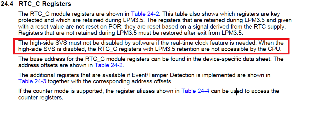
    please ensure that the RTC interrupt does not appear while SVS is disabled if this is the case the is not able to clear the RTC interrpt flags which means it will never leave the ISR.

    See also following user guide section:

  • Hi Dietmar

    Thanks for highlighting that...but...we are not going into LPM3.5...main power simply fails so its a no power situation.
    And, as its unknown that power is going to be cut-off, the program does nothing in advance.

    Ergo, the SVS (or any other peripheral) is not touched in advance of the power failure & remains as is.

  • Hi,

    it's not related to LPM3.5 even if you disable SVS in Active Mode you run into this problem.

    Anyway if you do not touch SVS it's someting different. So does this behavior appear with debugger connected?

    If yes can you please try to debug this and check if RTC is counting and if the oscillator fault flags are properly cleared.

  • Hi Dietmar

    The SVS is altered as per the example project msp430f665x_ucs_03.c

    And yes i do have the debugger connected.
    While the MCU is running the RTC DOES tick over (both in my PCB and in the TI target board) .

    And my oscillator checks are in setup in the following loop:

    while (SFRIFG1 & OFIFG) // Check OFIFG fault flag
    {
            UCSCTL7 &= ~(DCOFFG | XT1LFOFFG | XT2OFFG); // Clear OSC fault flags
            SFRIFG1 &= ~OFIFG; // Clear OFIFG fault flag
    }

    Even before any changes that Ryan suggested, the RTC was running while main power was applied.

    i also have this line at the beginning of my setup 
               BAKMEM3 = SYSRSTIV;     // store the reg for the last startup.
    which returns 2h which i believe is BOR.

    AUXVCC3 is connected directly to the backup power supply (both PCB & target board).
    And from the scope probe i do see the XT1 oscillator continuing to run when main power is removed.
    And from my DMM i see the power draw to be 0.9 uA regardless of main power ON or OFF so i assume it indicates that everything associated with AUXVCC3 continues to function when main power is removed.

    So it would appear that something is set on power down that puts the RTC into a HOLD state. Where should i look for that?

    But i am also puzzled why Ryan's code makes the RTC continue to tick over under backup power yet my copy of Ryan's code does not....same code, same target board, same jumper settings(?), same MCU.

  • Moshe,

    My test ran solely from FET power and not a bench supply, can you attempt the same and keep the debugger open for the duration of the test? Also supply chip markings if you are concerned about the lot quality.

    Regards,
    Ryan
  • Hi Ryan
    Yes i did that, and yes the RTC ticked over...but thats only because the MCU is still running (somewhere) as evidenced by being able to step thru the code in the while loop and in the ISR when those jumpers are removed, so it proves nothing except that one can remove J4, J11, & J12 and the chip still runs under FET power...i'm not sure how except it does.

    The test should be performed with the RTC and the main power source from an external source but NOT the FET.
    The RTC supplied solely from the external source so as to remove any issues with the AUXVCC3 chargers.
    Then remove main power & return it a minute or more later and read the RTC registers....in THAT test and under THOSE circumstances the RTC does not tick over....(although the crystal keeps running & the registers are kept alive).

    I dont think its a chip lot quality but rather a setting (or possibly even a connection) issue.

    regards
    Moshe

  • Hi Moshe,

    I don't think we can rely on the debugger to accurately re-connect and display the RTC register values after the AUXVCC3 supply causes the MCU to enter and wake from a LPM3.5-like state. Can you use some other form of output (LEDs, UART, LCD, etc.) to evaluate your RTC?

    Regards,
    Ryan
  • Hi Ryan
    I communicate with my design board via RS232. Thats how i picked up the issue in the first place.
    When power is restored, i read the RTC again and noticed the time only ticked over a few secs rather than the few minutes power was OFF.
    The only reason i went to using a target board was because you said it worked on your setup.

    So...given that...and communicating with my board...I have established that:
    1. The 32K crystal continues to oscillate when main power is removed.
    2. The contents of the RTC registers retain their values when power is removed.

    It is almost as if RTCCTL1 has a RTCHOLD assignment.....is that possible?
    Is there another setting that makes the RTC continue to tick over or conversely go into hibernation?
    Is there a parallel set of registers that are used in the power down scenario that i must then copy (on restart) into the RTC registers that i use for reading the time?

    regards
    moshe

  • Hi moshe,

    I've applied the following code to my MSP-TS430PZ100B target board and connected the MSP-FET pin 2 to VCC, pin 9 to GND, pin 12 to P1.3/TXD, and pin 14 to P1.2/RXD.  I can see RTCSEC incrementing properly, even during AUXVCC3 supply, using a terminal program @ 9600 baud (after DVCC has been re-connected).

    #include <msp430.h>
    
    void SetVcoreUp (unsigned int level);
    
    void main(void)
    {
        WDTCTL = WDTPW | WDTHOLD;               // Stop WTD
    
        // Setup P11.5 RTCCLK
        P9DIR |= BIT0;            // RTCCLK set out to pins
        P9SEL |=BIT0;
    
        // Setup P1.2 UCA0RXD, P1.3 UCA0TXD
        P1SEL |= BIT2 | BIT3;                   // Set P1.2, P1.3 to non-IO
        P1DIR |= BIT2 | BIT3;                   // Enable UCA0RXD, UCA0TXD
    
        SetVcoreUp (0x01);
        SetVcoreUp (0x02);
    
        //Enable Charger
        AUX3CHCTL = AUXCHKEY + AUXCHC_1 + AUXCHV_1 + AUXCHEN;
    
    //    // Initialize LFXT1
        UCSCTL6 &= ~(XT1OFF);                   // Enable XT1
    //    UCSCTL6 |= XCAP_3;                      // Internal load cap
        // Loop until XT1, XT2 & DCO fault flag is cleared
    
        __bis_SR_register(SCG0);                  // Disable the FLL control loop
        UCSCTL0 = 0x0000;                         // Set lowest possible DCOx, MODx
        UCSCTL1 = DCORSEL_5;                      // Select DCO range 24MHz operation
        UCSCTL2 = FLLD_1 + 487;                   // Set DCO Multiplier for 16MHz
                                                  // (N + 1) * FLLRef = Fdco
                                                  // (487 + 1) * 32768 = 16MHz
                                                  // Set FLL Div = fDCOCLK/2
        __bic_SR_register(SCG0);                  // Enable the FLL control loop
    
        // Worst-case settling time for the DCO when the DCO range bits have been
        // changed is n x 32 x 32 x f_MCLK / f_FLL_reference. See UCS chapter in 5xx
        // UG for optimization.
        // 32 x 32 x 16 MHz / 32,768 Hz = 500000 = MCLK cycles for DCO to settle
        __delay_cycles(500000);
    
        do
        {
            UCSCTL7 &= ~(XT2OFFG | XT1LFOFFG | DCOFFG);
            // Clear XT2,XT1,DCO fault flags
           SFRIFG1 &= ~OFIFG;                  // Clear fault flags
        } while (SFRIFG1 & OFIFG);              // Test oscillator fault flag
    
        // Start RTC calendar mode
        RTCCTL0_H = RTCKEY_H;                   // Unlock RTC_C module
        RTCCTL0_L |=  RTCRDYIE; //              // Enable RTC time event,
        RTCCTL1 |= RTCBCD;
         RTCCTL13 &=  ~(RTCCALF_3);  //Clear all RTCCALF bits since they may have previous RTCCALF value.
        RTCCTL13 |=  RTCCALF_1;     //512 Hz RTC output
        RTCCTL1 &= ~(RTCHOLD);  //In this case, RTCHOLD may be set with POR.  However, it does not
                                //get set in the case VDSYS goes off, but it does get set when it comes
                                //back.  Therefore, it should get reset to enable operation.
        RTCCTL0_H = 0;
    
        // Setup eUSCI_A0
        UCA0CTLW0 |= UCSWRST;                   // **Put state machine in reset**
        UCA0CTLW0 |= UCSSEL_1;                  // CLK = ACLK
        UCA0BRW_L = 0x03;                       // 32kHz/9600=3.41 (see User's Guide)
        UCA0BRW_H = 0x00;                       //
        UCA0MCTLW = 0x5300;                     // Modulation UCBRSx=0x53, UCBRFx=0
        UCA0CTLW0 &= ~UCSWRST;                  // **Initialize USCI state machine**
        UCA0IE |= UCRXIE;                       // Enable USCI_A0 RX interrupt
    
        __bis_SR_register(GIE);
        while(1) __no_operation();
    }
    
    // RTC Interrupt Service Routine
    #pragma vector=RTC_VECTOR
    __interrupt void rtc_isr(void)
    {
        switch (__even_in_range(RTCIV, 16))
        {
            case RTCIV_NONE:                    // No interrupts
                break;
            case RTCIV_RTCOFIFG:                // RTCOFIFG
                break;
            case RTCIV_RTCRDYIFG:               // RTCRDYIFG
                __no_operation();
                break;
            case RTCIV_RTCTEVIFG:               // RTCEVIFG
                __no_operation();
                break;
            case RTCIV_RTCAIFG:                 // RTCAIFG
                __no_operation();
                break;
            case RTCIV_RT0PSIFG:                // RT0PSIFG
                break;
            case RTCIV_RT1PSIFG:                // RT1PSIFG
                break;
    //        case 14: break;                   // Reserved
            case 16: break;                     // Reserved
            default: break;
        }
    }
    
    // USCI_A0 interrupt service routine
    #if defined(__TI_COMPILER_VERSION__) || defined(__IAR_SYSTEMS_ICC__)
    #pragma vector=USCI_A0_VECTOR
    __interrupt void USCI_A0_ISR(void)
    #elif defined(__GNUC__)
    void __attribute__ ((interrupt(USCI_A0_VECTOR))) USCI_A0_ISR (void)
    #else
    #error Compiler not supported!
    #endif
    {
        switch (__even_in_range(UCA0IV, 4))
        {
            case USCI_NONE: break;              // No interrupt
            case USCI_UART_UCRXIFG:             // RXIFG
                while (!(UCA0IFG & UCTXIFG)) ;  // USCI_A0 TX buffer ready?
                UCA0TXBUF = ((RTCSEC>>4)&0x0F) + 48;    // RTCSEC high byte
                while (!(UCA0IFG & UCTXIFG)) ;  // USCI_A0 TX buffer ready?
                UCA0TXBUF = (RTCSEC&0x0F)+48;   // RTCSEC low byte
                while (!(UCA0IFG & UCTXIFG)) ;  // USCI_A0 TX buffer ready?
                UCA0TXBUF = 10;
                while (!(UCA0IFG & UCTXIFG)) ;  // USCI_A0 TX buffer ready?
                UCA0TXBUF = 13;
                break;
            case USCI_UART_UCTXIFG: break;      // TXIFG
            case USCI_UART_UCSTTIFG: break;     // TTIFG
            case USCI_UART_UCTXCPTIFG: break;   // TXCPTIFG
            default: break;
        }
    }
    
    void SetVcoreUp (unsigned int level)
    {
      // Open PMM registers for write
      PMMCTL0_H = PMMPW_H;
      // Set SVS/SVM high side new level
      SVSMHCTL = SVSHE + SVSHRVL0 * level + SVMHE + SVSMHRRL0 * level;
      // Set SVM low side to new level
      SVSMLCTL = SVSLE + SVMLE + SVSMLRRL0 * level;
      // Wait till SVM is settled
      while ((PMMIFG & SVSMLDLYIFG) == 0);
      // Clear already set flags
      PMMIFG &= ~(SVMLVLRIFG + SVMLIFG);
      // Set VCore to new level
      PMMCTL0_L = PMMCOREV0 * level;
      // Wait till new level reached
      if ((PMMIFG & SVMLIFG))
        while ((PMMIFG & SVMLVLRIFG) == 0);
      // Set SVS/SVM low side to new level
      SVSMLCTL = SVSLE + SVSLRVL0 * level + SVMLE + SVSMLRRL0 * level;
      // Lock PMM registers for write access
      PMMCTL0_H = 0x00;
    }
    

    Regards, Ryan

  • Hello Moshe,

    I have seen such issue at some of the designs with MSP430F6736 due to RTCHOLD bit getting SET. When there is power loss, sometime MCU gets RESET first before getting power down and RTC may get stop due to RTCHOLD gets set at reset and code couldn't reach on the instruction where you are making it clear. However since you are using  MSP430F6736A, you can use RTCLOCK in your application. In your initialization code of RTC just set RTCLOCK bit in RTCCTL3.

    For MSP430F6736 (without A), I would recommend below low level init function  for this issue:

    For CCS compiler:

    int _system_pre_init(void)

    {

     //clear RTC

      RTCCTL0_H=RTCKEY_H; //unlock RTC_C Module

      RTCCTL13 &=~(RTCHOLD);

      RTCCTL0_H=0;

      return 1;

    }


    For IAR compiler:

    int __low_level_init(void)

    {

     //clear RTC

      RTCCTL0_H=RTCKEY_H; //unlock RTC_C Module

      RTCCTL13 &=~(RTCHOLD);

      RTCCTL0_H=0;

      return 1;

    }


     Regards,

    Vikas Chola

  • Hi Ryan and Vikas

    Firstly Vikas...thanks for your input.
    However, if i set RTCLOCK in RTCCTL3 then my RTC interrupt never gets called because the RTC is, well, locked which is not what i want.
    But it gave me an idea because of what you said about a possible reset not reaching my RTC inialisation code and so remained locked....more about this later.

    Secondly Ryan...thanks for the idea about using the Rx & Tx on the target board.
    Q1. I was under the impression that setting a P1DIR bit sets it as an output...but Rx is an input..yet it still received a byte - WHY???

    Now my results:
    Based on what Vikas wrote about a reset, i added this code as the first lines of main
    RTCCTL0_H = RTCKEY_H; // Unlock RTC_C module
    RTCCTL1 &= ~(RTCHOLD);
    RTCCTL0_H = 0; // lock it
    On the target board that seemed to enable the RTC to tick over when power was removed.....GREAT!!!
    I then COMMENTED OUT those lines and retried the exercise and it STILL worked....WHY....why should it now continue to work???

    I then moved to my board and tried the same thing....IT DIDNT WORK, the RTC didnt tick over on main power removal.
    In desperation, i disconnected the FET and retried....THAT appeared to WORK.
    I then repeated the exercise a few times and each time the RTC ticked over....GREAT!!
    I then left it to write this note but thought let me try one more time...this time it did NOT work.
    I retried about 30 secs later and it DID work.

    It appears that SOMETIMES the RTC ticks over, and SOMETIMES it doesn't...and that would support what Vikas was saying about a reset happening but not reaching my unlock code.
    Q2. This would appear to indicate a serious shortcoming in the chip if i need to depend on the RTC ticking over when main power is removed...is that a valid assertion?

    Q3. How can I conclusively PROVE this?
    Q4. What can i do to PREVENT this?
    Q5. Why does the target board ALWAYS work now?

    regards
    moshe

    ps....i havent marked this as a resolution because i dont know if i have conclusively resolved my issue.
  • Hi moshe,

    First, PxDIR is ignored as PxSEL takes priority in deciding pin functionality. Second, it seems that your custom board has a design flaw where switching between DVCC and AUXVCC3 creates a situation where the device resets/resumes operation with DVCC but then re-enters AUXVCC3 before RTC initialization is executed. You could evaluate this by monitoring the VCC, AUX, and RST lines with an oscilloscope. If you could find a way to avoid your RTC ISR then I would suggest using RTCLOCK. Otherwise try increasing your VCC capacitance.

    Regards,
    Ryan
  • thank you Ryan

    i had a further look in my ISR and noticed that i had set RTCCTL1 |= RTCHOLD while accessing the clock...which i don't need to do & which i suppose COULD be a reason for the whole issue if power goes down in the instant after i've set that!...so that has now been deleted.

    I might be a little slow here...BUT.... i dont understand the use of RTCLOCK...as i understand it, & seen in the debugger, when that is set, the RTC time registers are not available so how does that help anything in getting the time....what am i missing here??

    And finally, i do need the RTC ISR so i will investigate the various caps on the board - thank you for that one.

    regards
    moshe
  • RTCLOCK ensures that all protected RTC register bits are not written to or reset upon wake-up from LPM3.5, explained in Section 24.2.9 of the Users Guide.

    Regards,
    Ryan
  • Hi Ryan

    Just to wrap this up for others who may have been watching this post.

    The suggestion of increasing Vcc cap WORKED!!!!

    i noticed the Vcc cap on the target board was 32uF and on my custom board it was 10uF...so i increased it to 32uF...so it would appear that the minimum cap on Vcc must be around 32uF if one wants the RTC to continue ticking over.

    QUESTION: why would the cap on Vcc have any bearing on what happens with the RTC ticking over??

    thanks again for your efforts

    moshe

  • Hi moshe,

    Glad to hear that you issue is resolved! I think it has to do with the facts we already know, switching between the two supplies creates a bounce effect where the MCU starts up execution code with DVCC but then switches to AUXVCC3 before the RTC has been properly initialized, creating the fail state observed. Increasing Vcc capacitance reduces this effect and allows fluent switching between the two supplies without unnecessary toggling.

    Regards,
    Ryan
  • Hi Ryan

    thanks for all your input Ryan.

    Ideally i need to set RTCLOCK just before the POR is triggered...is there a mechanism in MCU (or userguide) to do that (i dont believe there is).

    cheers

    moshe

**Attention** This is a public forum