This thread has been locked.

If you have a related question, please click the "Ask a related question" button in the top right corner. The newly created question will be automatically linked to this question.

MSP430F5438A: MSP430F5438A ADC SAMPLING FREQUENCY

Part Number: MSP430F5438A
Other Parts Discussed in Thread: MSPWARE, , Z-STACK

Hello sir,  
This is my ADC configuration

ADC12CTL0 = ADC12ON + ADC12SHT0_4 + ADC12MSC;        
ADC12CTL1 =  ADC12SHP + ADC12CONSEQ_2  + ADC12SSEL_3 + ADC12DIV_4 ;

for 8-bit Resolution

ADC12SSEL_3 = (SMCLK 1.045Mhz)

ADC12SHT0_4 = 64 ADC12CLK CYCLES

ADC12DIV_4 = Divide by 5

so,

ADC clock frequency = adc source clock / predivider x divider    //   Predivider = 1

                                      =  1.045Mhz / 1 x 5

                                      =  209Khz

ADC sampling Frequency  = ADC clock frequency / ((conversion cycles) + (sample_hold cycles) + 1)

Conversion cycles = ADC resolution + 1 = 8+1 = 9

ADC sampling frequency = 209000 / ((9)+(64)+1)

                                             = 2824.324 = 2.8khz

ADC sampling Frequency = 2.8khz

Sir, Please clarify that is above ADC sampling Frequency calculation is Correct ? if not please convey the correct way of calculation.

Thanks in advance

  • Hello Shiva,

    Thanks for your post. I see that you're using the Multiple Sample and Convert (ADC12MSC) Bit to sample continuously, and you're using Repeat-Single-Channel Mode (ADC12CONSEQ_2). I went through your calculations, and they seem to be correct, although I'm not sure where the extra 1 in the denominator comes from in your equation (shown below).

    ADC Sampling Frequency = 209000 / (9 + 64 + 1)

    Perhaps, you're assuming worst case for the sync time (tsync), but this sync would only occur before the first sample and not again, since you're using Pulse Sample Mode. This is discussed in the following thread for your reference.

    Hope this helps!

    Regards,

    James

    MSP Customer Applications

  • Thanks for reply,
    Sir , please go through the modified formula and let me know about its correctness.

    ADC clock frequency = adc source clock / predivider x divider // Predivider = 1
    ADC sampling Frequency = ADC clock frequency / ((conversion cycles) + (sample_hold cycles))

    Moreover,
    can we change the ACLK, MCLK, SMCLK clock frequencies for ADC conversion ?
    Because In the UCS Block diagram AClK, SMCLK, MCLK are having divider and these are software selectable, if changeble how to change.

    Thanks and regards
  • please reply sir
  • Hello,

    Yes, you can change which clock sources the ADC module. You can find the more details about how to do this and the applicable registers in the MSP430x5xx and MSP430x6xx Family User's Guide (read through the ADC12_A chapter). Also, I would recommend referring to our code examples in Resource Explorer in CCS. You may need to install MSPWare too.

    Regards,

    James

    MSP Customer Applications

  • thanks for your reply
    sir,
    1) what i am asking Is ACLK = 32768, SMCLK = 1.048MHz , MCLK = 1.048MHz frequencies are fixed or not? If these are not fixed how can i change?
    2) Please check the below code

    #include "msp430f5438A.h"
    #include<stdio.h>
    #include<string.h>
    #include <stdint.h>

    void adcfunction(void);
    void adcInit(void);
    char buffer[100];
    static int16_t SavedADC12MEM1;
    float values;

    #pragma vector=ADC12_VECTOR
    __interrupt void ADC12_ISR(void)
    {
    SavedADC12MEM1 = ADC12MEM0;
    __bic_SR_register_on_exit(LPM0_bits);
    }
    void adcInit(void)
    {
    P6SEL |= BIT7;
    P6DIR &= ~BIT7;

    REFCTL0 |= REFMSTR+REFVSEL_2+REFON+REFTCOFF;
    ADC12CTL0 = ADC12ON + ADC12SHT0_2 + ADC12MSC;
    ADC12CTL1 = ADC12SHP + ADC12CONSEQ_2 + ADC12SSEL_3 + ADC12DIV_4 ;
    ADC12CTL2 = ADC12PDIV + ADC12RES_0;
    ADC12MCTL0 = ADC12INCH_7+ ADC12SREF_1;
    ADC12IE = BIT0;
    __delay_cycles(10);
    }

    void adcfunction(void)
    {
    ADC12CTL0 |= ADC12ENC | ADC12SC;

    __bis_SR_register(LPM0_bits+GIE);
    __no_operation();
    }

    int main(void)
    {
    WDTCTL = WDTPW + WDTHOLD;
    int voltages;

    adcInit();
    while(1)
    {

    adcfunction();
    voltages= SavedADC12MEM1;
    P5SEL |= BIT6 + BIT7;
    UCA1CTL1 |= UCSWRST;
    UCA1CTL1 |= UCSSEL__SMCLK;
    UCA1BR0 = 9;
    UCA1BR1 = 0;

    UCA1MCTL = UCBRS_0;

    UCA1CTL1 &= ~UCSWRST;
    int k=0;

    sprintf(buffer,"%d",voltages);

    while(buffer[k])
    {
    while(!(UCA1IFG&UCTXIFG));
    UCA1TXBUF = buffer[k++];
    }
    while(!(UCA1IFG&UCTXIFG));
    UCA1TXBUF = '\r';
    while(!(UCA1IFG&UCTXIFG));
    UCA1TXBUF = '\n';

    __bis_SR_register(LPM0_bits+GIE);

    }
    }

    ADC Clock Frequency = (ADC SOURCE CLOCK) / ((PRE-DIVIDER) * (DIVIDER))
    ADC Sampling Frequency = (ADC CLOCK FREQUENCY) / (CONVERSION CYCLES + SAMPLE-HOLD CYCLES)

    ADC CLOCK = 1048576 / 4*5 = 52428.8Hz
    ADC sampling frequency = 52428.8 /(9+16) = 2097.152Hz = 2.097KHz

    i) is my sampling frequency calculation is correct?

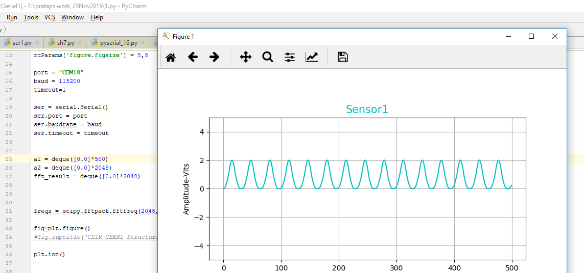
    ii) from Function generator i am giving sine wave as input with frequency (0.1Hz to 1000Hz ) amplitude is 1vpp , i am using Python to reproduce the output (sine wave) i am able to reproduce the sine wave from 0.1Hz to 1Hz but not beyond the 1Hz, i have gone upto 1KHz but no use i am not able reproduce the output. is i made any mistake in my code please notify me. In python i am reading the Com port with 115200 baud rate as i initialized the UART.

    first output picture with input frequency 1Hz

    second output picture with input frequency 10Hz

    Third output picture with input frequency 0.1Hz

  • To answer your question: MCLK/SMCLK/ACLK can be adjusted, by adjusting the underlying clock(s) that drive them. Example msp430x54xA_UCS_2.c [SLAC375F], e.g. shows how to switch the DCO to 12MHz. Keep in mind that that will affect your CPU (MCLK) and your UART (SMCLK).

    I suggest that, rather than trying to fine-tune the system to indirectly tune the CONSEQ=2 sample rate, instead use a timer to pace the ADC (ADC12SHS) and CONSEQ=0. That will allow you to tune the sample rate independently of everything else.

    My arithmetic on the sample rate agrees with yours. However, my suspicion is that your UART is what's throttling your sample rate. At 115200bps, you can theoretically get 115200/10/5=2304sps, but that assumes you're keeping the UART completely busy, and I suspect you aren't, due to spinning on TXIFG and the sprintf() call.

    I'm not quite sure what I should see in the 10Hz trace, since there's much less detail than in the others. One observation is that the readings near 0 require fewer characters to transmit (3 instead of 5) which may be why you seem to be getting more samples near 0 than near the peaks.
  • Thanks for your reply,

    Actually my senior use the Z-stack for MSP430f5438a in this he used adc and transmitted data through UART , i saw the code which is Genericapp.c file he didn't changed the clock so, i think SMCLK will be 1.04mhz , but in the uart configuration he used 460800 baudrate for 12Mhz clock with BRO = 26 ,BR1 = 0 ,and the data received corrected waveforms appeared are also correct. How this is possible

  • Can you compare your code with their code to see what's different?  had a lot of good feedback in his previous post, and I agree that you should not try to indirectly tune the sampling rate. Regarding the UART baud rate,  I wouldn't recommend using an DCO frequency of 1.04MHz with a baud rate of 460800 baud - you'll need something higher and 12MHz is a good place to start. You can quickly calculate the USCI dividers based on your DCO frequency (clock speed) and desired baud rate using the USCI UART Baud Rate Calculator.

    I did this for both 1.04MHz and 12MHz. Notice the high bit error for the lower clock speed.

    Regards,

    James

    MSP Customer Applications

  • Thanks for reply,
    i am able to calculate the Baudrate of UART(USCIA1(USB-UART)) as well as sampling frequency of ADC. Sir please see my code in previous posts is there any mistake of ADC initializations and in UART as well as Calculations Please let me Know.

    Thankyou sir
  • Have you looked at our code examples yet? You can find them in Resource Explorer inside CCS. This will help you more than anything at the moment. Rather than tell you everything to fix, I would recommend starting with an ADC code example and carefully and incrementally add your code.

    Fundamentally, you're not using an ADC ISR. What's happening is your ADC code is getting executed in the while(1) loop, so the speed and frequency of your sampling depends on the CPU frequency and how much is being done inside the while(1) loop after the adcfunction().

    You've been asking about setting the sampling rate, but it's not being used in your code. In adcfunction(), you're triggering the ADC12ENC (enable conversions) and ADC12SC (start conversion) bits manually. Instead, you should set your sampling rate (as already discussed) and then just enable and start the conversions only ONCE. Then, as you can see in the code example below, the ADC ISR fires at the sampling rate, captures data, and then returns to main().

    In the 'msp430x54xA_adc12_07.c' code example below, there's an array called "results[]" where the ADC conversions are saved. To get started, you can increase the size of this array to capture more data, run the code, and then halt it with the debugger to see the captured results.

    msp430x54xA_adc12_07.c

    /* --COPYRIGHT--,BSD_EX
     * Copyright (c) 2012, Texas Instruments Incorporated
     * All rights reserved.
     *
     * Redistribution and use in source and binary forms, with or without
     * modification, are permitted provided that the following conditions
     * are met:
     *
     * *  Redistributions of source code must retain the above copyright
     *    notice, this list of conditions and the following disclaimer.
     *
     * *  Redistributions in binary form must reproduce the above copyright
     *    notice, this list of conditions and the following disclaimer in the
     *    documentation and/or other materials provided with the distribution.
     *
     * *  Neither the name of Texas Instruments Incorporated nor the names of
     *    its contributors may be used to endorse or promote products derived
     *    from this software without specific prior written permission.
     *
     * THIS SOFTWARE IS PROVIDED BY THE COPYRIGHT HOLDERS AND CONTRIBUTORS "AS IS"
     * AND ANY EXPRESS OR IMPLIED WARRANTIES, INCLUDING, BUT NOT LIMITED TO,
     * THE IMPLIED WARRANTIES OF MERCHANTABILITY AND FITNESS FOR A PARTICULAR
     * PURPOSE ARE DISCLAIMED. IN NO EVENT SHALL THE COPYRIGHT OWNER OR
     * CONTRIBUTORS BE LIABLE FOR ANY DIRECT, INDIRECT, INCIDENTAL, SPECIAL,
     * EXEMPLARY, OR CONSEQUENTIAL DAMAGES (INCLUDING, BUT NOT LIMITED TO,
     * PROCUREMENT OF SUBSTITUTE GOODS OR SERVICES; LOSS OF USE, DATA, OR PROFITS;
     * OR BUSINESS INTERRUPTION) HOWEVER CAUSED AND ON ANY THEORY OF LIABILITY,
     * WHETHER IN CONTRACT, STRICT LIABILITY, OR TORT (INCLUDING NEGLIGENCE OR
     * OTHERWISE) ARISING IN ANY WAY OUT OF THE USE OF THIS SOFTWARE,
     * EVEN IF ADVISED OF THE POSSIBILITY OF SUCH DAMAGE.
     *
     *******************************************************************************
     * 
     *                       MSP430 CODE EXAMPLE DISCLAIMER
     *
     * MSP430 code examples are self-contained low-level programs that typically
     * demonstrate a single peripheral function or device feature in a highly
     * concise manner. For this the code may rely on the device's power-on default
     * register values and settings such as the clock configuration and care must
     * be taken when combining code from several examples to avoid potential side
     * effects. Also see www.ti.com/grace for a GUI- and www.ti.com/msp430ware
     * for an API functional library-approach to peripheral configuration.
     *
     * --/COPYRIGHT--*/
    //******************************************************************************
    //  MSP430F543xA Demo - ADC12_A, Repeated Single Channel Conversions
    //
    //  Description: This example shows how to perform repeated conversions on a
    //  single channel using "repeat-single-channel" mode.  AVcc is used for the
    //  reference and repeated conversions are performed on Channel A0. Each
    //  conversion result is moved to an 8-element array called results[].  Test by
    //  applying a voltage to channel A0, then running. Open a watch window in
    //  debugger and view the results. Set Breakpoint1 in the index increment line
    //  to see the array value change sequentially and Breakpoint to see the entire
    //  array of conversion results in "results[]" for the specified Num_of_Results.
    //  This can run even in LPM4 mode as ADC has its own clock (MODOSC)
    //
    //                MSP430F5438A
    //             -----------------
    //         /|\|                 |
    //          | |                 |
    //          --|RST              |
    //            |                 |
    //     Vin -->|P6.0/A0          |
    //            |                 |
    //
    //
    //   M Morales
    //   Texas Instruments Inc.
    //   June 2009
    //   Built with CCE Version: 3.2.2 and IAR Embedded Workbench Version: 4.11B
    //******************************************************************************
    
    #include <msp430.h>
    
    #define   Num_of_Results   8
      
    volatile unsigned int results[Num_of_Results];
                                                // Needs to be global in this
                                                // example. Otherwise, the
                                                // compiler removes it because it
                                                // is not used for anything.
    
    int main(void)
    {
      WDTCTL = WDTPW+WDTHOLD;                   // Stop watchdog timer
      
      P6SEL |= 0x01;                            // Enable A/D channel A0
      
      /* Initialize ADC12_A */ 
      ADC12CTL0 = ADC12ON+ADC12SHT0_8+ADC12MSC; // Turn on ADC12, set sampling time
                                                // set multiple sample conversion
      ADC12CTL1 = ADC12SHP+ADC12CONSEQ_2;       // Use sampling timer, set mode
      ADC12IE = 0x01;                           // Enable ADC12IFG.0
      ADC12CTL0 |= ADC12ENC;                    // Enable conversions
      ADC12CTL0 |= ADC12SC;                     // Start conversion
      
      __bis_SR_register(LPM4_bits + GIE);       // Enter LPM4, Enable interrupts
      __no_operation();                         // For debugger  
    }
    
    #if defined(__TI_COMPILER_VERSION__) || defined(__IAR_SYSTEMS_ICC__)
    #pragma vector=ADC12_VECTOR
    __interrupt void ADC12ISR (void)
    #elif defined(__GNUC__)
    void __attribute__ ((interrupt(ADC12_VECTOR))) ADC12ISR (void)
    #else
    #error Compiler not supported!
    #endif
    {
      static unsigned char index = 0;
    
      switch(__even_in_range(ADC12IV,34))
      {
      case  0: break;                           // Vector  0:  No interrupt
      case  2: break;                           // Vector  2:  ADC overflow
      case  4: break;                           // Vector  4:  ADC timing overflow
      case  6:                                  // Vector  6:  ADC12IFG0
        results[index] = ADC12MEM0;             // Move results
        index++;                                // Increment results index, modulo; Set Breakpoint1 here
       
        if (index == 8)
          index = 0;                            // Reset the index; Set Breakpoint here 
          
      case  8: break;                           // Vector  8:  ADC12IFG1
      case 10: break;                           // Vector 10:  ADC12IFG2
      case 12: break;                           // Vector 12:  ADC12IFG3
      case 14: break;                           // Vector 14:  ADC12IFG4
      case 16: break;                           // Vector 16:  ADC12IFG5
      case 18: break;                           // Vector 18:  ADC12IFG6
      case 20: break;                           // Vector 20:  ADC12IFG7
      case 22: break;                           // Vector 22:  ADC12IFG8
      case 24: break;                           // Vector 24:  ADC12IFG9
      case 26: break;                           // Vector 26:  ADC12IFG10
      case 28: break;                           // Vector 28:  ADC12IFG11
      case 30: break;                           // Vector 30:  ADC12IFG12
      case 32: break;                           // Vector 32:  ADC12IFG13
      case 34: break;                           // Vector 34:  ADC12IFG14
      default: break; 
      }
    }

    Regards,

    James

    MSP Customer Applications

**Attention** This is a public forum