This thread has been locked.

If you have a related question, please click the "Ask a related question" button in the top right corner. The newly created question will be automatically linked to this question.

MSP430FR5994: I2C unable to receive from slave

Part Number: MSP430FR5994
Other Parts Discussed in Thread: MSP430FR2311

I2C unable to receive from slave MSP430FR5994

The transmit part of this test code (commented out) works ok and sends data correctly to the slave.  But the receive part (shown) is not able

to receive anything from the slave.  Scope waveform shows just a short positive pulse on the i2c data line and the clock line remains solid high.

During initialization:

UCB1CTLW0 comes out 0x680.  Thus UCMST (0x800) is not set and UCTR (0x10) is not set in transmit mode.

When running receive only one byte, only get a short pulse on data line with clk staying high,

So it is not sending the slave address on receive.  ConfigI2C() is still called prior to running the Testi2c() program, but is now redundant.


/*******************************************************************************

         Configure USCI_B1 for I2C mode

         400khz clock

         Writes to pot in 68.8us


*******************************************************************************/

void ConfigI2C(void)

{

    // Configure GPIO for i2c:

    P5SEL0 |= BIT0 | BIT1;

    P5SEL1 &= ~(BIT0 | BIT1);


    //UCB1CTLW0 = UCSWRST;                    // put eUSCI_B in reset state

    UCB1CTLW0 |= (UCMODE_3 | 0x800 | UCSSEL__SMCLK ) ; // I2C master mode, SMCLK

    UCB1BRW = 0x12;                          // baudrate = SMCLK / 18.  With this fclk=400khz or 2.5us.  Writes in 68.8us to pot.

    //UCB1CTLW0 &= ~UCSWRST;                  // clear reset register

    UCB1IE |= UCTXIE0 | UCNACKIE;           // transmit and NACK interrupt enable


}


/*************************************************************************

 *              Transmit bytes to slave i2c

 *   Transmit start, slave adx, command, data, stop  to slave: (could see nack)

 ************************************************************************/

void TransmitBytesI2c(uint8 nbytes)

{

    TxIrqFlag=1;                   //indicate now transmitting to irq


    UCB1CTLW0 = UCSWRST;                    // put eUSCI_B in reset state

    UCB1I2CSA = 0x04c;         // 4c configure slave adx.  MCSID bat U3=0x1a

    UCB1CTLW0 |= UCMODE_3 | UCMST | UCSSEL__SMCLK; //0x680 I2C master mode, SMCLK

    TXByteCtr = nbytes;                 // Load TX byte counter

    ByteCnt =0;                         //inc data byte counter for irq

    UCB1CTLW0 &= ~UCSWRST;                  // clear reset register

    while (UCB1CTLW0 & UCTXSTP);        // Ensure stop condition got sent


    UCB1IE |= UCTXIE0 | UCNACKIE;           // transmit and NACK interrupt enable

    UCB1CTLW0 |= (UCTR | UCTXSTT);        //I2C transmit start condition

}

/*************************************************************************

//Read Slave Data

//Send start, slave adx, instruction wo stop

//then send start, slave adx w read, read slave data, stop:

 *

 * start is data goes down with clock high.

**************************************************************************/

uint8 Read1byteI2c(uint8 SlaveAdx)

{

    //TransmitBytesI2c( 1);                //1 byte after slave adx = 0 command, stop

    //__delay_cycles(1000);           // wait to finish writing to slave


    TxIrqFlag=0;                   //indicate now receiving to irq


    UCB1CTLW0 = UCSWRST;                    // put eUSCI_B in reset state

    UCB1I2CSA = 0x04c;         // 4c configure slave adx.  MCSID bat U3=0x1a

    //UCB1TBCNT = 1;              //no bytes to be received

    UCB1CTLW0 &= ~UCTR ;         //clear UCTR for receive//UCB1CTLW0 = UCSWRST;                    // put eUSCI_B in reset state

    UCB1CTLW0 |= UCMODE_3 | UCMST | UCSSEL__SMCLK; // 0x680 I2C master mode, SMCLK

    UCB1CTLW0 &= ~UCSWRST;                  // clear reset register


    UCB1IE |=  UCRXIE0 | UCNACKIE;  // receive and NACK interrupt enable

    UCB1CTLW0 =  UCTXSTT;        //I2c  Read slave data, start condition

    while (UCB1CTLW0 & UCTXSTP);        // Ensure stop condition got sent

    __delay_cycles(1000);           // wait to finish reading the slave


    return RxData;

}


/**********************************************************************

 *          TestI2c()  Sends MSB first

 *          3.3Vccp is always on the i2c chip.

 *          This routine is normally not called.  Must be called to test.

 *          It writes to the i2c chip and increments the data written.

 *********************************************************************/

void TestI2c(void)

{

    //SlaveFlag = 0;                          // Initialize SlaveFlag


    while(1)

    {

        __delay_cycles(50000);               // Delay between transmissions

        //write test data I2CData[1] to i2c pot:

        //TransmitBytesI2c( 2);                //2 bytes adx, command, stop


        __delay_cycles(1000);               // wait to finish writing to slave


        Read1byteI2c(0x4c);          //slave adx for qsm005 is 4c, mcsid u3 is 1a

      __delay_cycles(10000);           // wait to finish reading slave data


       // __bis_SR_register(LPM0_bits | GIE); // Enter LPM0 w/ interrupts                                       // Remain in LPM0 until all data                                           // is TX'd

        I2CData[1] = I2CData[1] +1 ;               // inc data for test!!!

    }

}


#if defined(__TI_COMPILER_VERSION__) || defined(__IAR_SYSTEMS_ICC__)

#pragma vector = EUSCI_B1_VECTOR

__interrupt void USCI_B1_ISR(void)

#elif defined(__GNUC__)

void __attribute__ ((interrupt(EUSCI_B1_VECTOR))) USCI_B1_ISR (void)

#else

#error Compiler not supported!

#endif

{


switch(__even_in_range(UCB1IV, USCI_I2C_UCBIT9IFG))

{

    case USCI_NONE:          break;     // Vector 0: No interrupts

    case USCI_I2C_UCALIFG:   break;     // Vector 2: ALIFG

    case USCI_I2C_UCNACKIFG:            // Vector 4: NACKIFG

        UCB1CTLW0 |= UCTXSTT;           // resend start if NACK

        break;

    case USCI_I2C_UCSTTIFG:  break;     // Vector 6: STTIFG

    case USCI_I2C_UCSTPIFG:  break;     // Vector 8: STPIFG

    case USCI_I2C_UCRXIFG3:  break;     // Vector 10: RXIFG3

    case USCI_I2C_UCTXIFG3:  break;     // Vector 12: TXIFG3

    case USCI_I2C_UCRXIFG2:             // Vector 14: RXIFG2

        ;

        break;

    case USCI_I2C_UCTXIFG2:  break;     // Vector 16: TXIFG2

    case USCI_I2C_UCRXIFG1:  break;     // Vector 18: RXIFG1

    case USCI_I2C_UCTXIFG1:  break;     // Vector 20: TXIFG1

    case USCI_I2C_UCRXIFG0:             // Vector 22: RXIFG0

        RxData = UCB1RXBUF;             // Get RX data

        break;


    case USCI_I2C_UCTXIFG0:             // Vector 24: TXIFG0 (txbuffer empty irq)

        if (TXByteCtr)                  // Check TX byte counter

        {

            UCB1TXBUF = I2CData[ByteCnt];  // Load TX buffer

            ByteCnt++;                  //inc the byte count

            TXByteCtr--;                // Decrement TX byte counter

        }

        else

        {

            if( TxIrqFlag==1)      //if a transmitter then send stop condition

                UCB1CTLW0 |= UCTXSTP;   // I2C stop condition

            UCB1IFG &= ~UCTXIFG;        // Clear USCI_B1 TX int flag

            __bic_SR_register_on_exit(LPM0_bits); // Exit LPM0

        }

        break;

    case USCI_I2C_UCBCNTIFG: break;     // Vector 26: BCNTIFG

    case USCI_I2C_UCCLTOIFG: break;     // Vector 28: clock low timeout

    case USCI_I2C_UCBIT9IFG: break;     // Vector 30: 9th bit

    default: break;


}

}


  • Hi John
    Two things you can check first:
    1. The SDA and SCL is pull up
    2. Can you get the ACK from the slave?
    By the way what' s the slave device?

    Best regards
    Gary
  • Great to hear from you, Gary:

    Yes this time I do have pullups on scl and sda(10k). Its running at clock speed of 400khz.
    The ack should work from the slave as it works correctly when sending data to the slave. Do get ack from slave when
    Writing to the slave.
    Even if the slave is dead the slave address should be sent by the uProc, shouldn’t it?

    The part is AD5259.

    Thanks,

    John
  • Hi John

    I think you add the stop between the write to the reading register and the read data like below

    You should repeat start without the stop when you send the instruction byte. It is very similar with the SMBus communication.

    Best regards

    Gary

  • Gary:

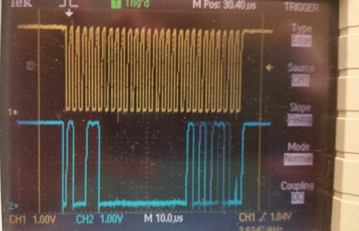
       Here is a waveform of transmit to the slave unit.  You can see the ack and the data going across.

  • Hi John
    Can't see your picture.
  • Sorry Gary
    But I must not know how to send the repeat start when sending the instruction byte
    because I thought the software automatically sends the instruction byte after the slave adx byte.
    When i do the second half doesn't the receive software also send a (repeat) start, adx byte, and then read back the data?

    Don't think the waveform got to the post. I just took a pict and emailed it to myself and cut and pasted it.
    John
  • Hi John

    You can refer to this code that I write to test the SMBus.That is based on the MSP430FR2311. But it is easy to transplant to MSP430FR5994

    msp430fr231x_read.c
    /* --COPYRIGHT--,BSD_EX
     * Copyright (c) 2014, Texas Instruments Incorporated
     * All rights reserved.
     *
     * Redistribution and use in source and binary forms, with or without
     * modification, are permitted provided that the following conditions
     * are met:
     *
     * *  Redistributions of source code must retain the above copyright
     *    notice, this list of conditions and the following disclaimer.
     *
     * *  Redistributions in binary form must reproduce the above copyright
     *    notice, this list of conditions and the following disclaimer in the
     *    documentation and/or other materials provided with the distribution.
     *
     * *  Neither the name of Texas Instruments Incorporated nor the names of
     *    its contributors may be used to endorse or promote products derived
     *    from this software without specific prior written permission.
     *
     * THIS SOFTWARE IS PROVIDED BY THE COPYRIGHT HOLDERS AND CONTRIBUTORS "AS IS"
     * AND ANY EXPRESS OR IMPLIED WARRANTIES, INCLUDING, BUT NOT LIMITED TO,
     * THE IMPLIED WARRANTIES OF MERCHANTABILITY AND FITNESS FOR A PARTICULAR
     * PURPOSE ARE DISCLAIMED. IN NO EVENT SHALL THE COPYRIGHT OWNER OR
     * CONTRIBUTORS BE LIABLE FOR ANY DIRECT, INDIRECT, INCIDENTAL, SPECIAL,
     * EXEMPLARY, OR CONSEQUENTIAL DAMAGES (INCLUDING, BUT NOT LIMITED TO,
     * PROCUREMENT OF SUBSTITUTE GOODS OR SERVICES; LOSS OF USE, DATA, OR PROFITS;
     * OR BUSINESS INTERRUPTION) HOWEVER CAUSED AND ON ANY THEORY OF LIABILITY,
     * WHETHER IN CONTRACT, STRICT LIABILITY, OR TORT (INCLUDING NEGLIGENCE OR
     * OTHERWISE) ARISING IN ANY WAY OUT OF THE USE OF THIS SOFTWARE,
     * EVEN IF ADVISED OF THE POSSIBILITY OF SUCH DAMAGE.
     *
     *******************************************************************************
     * 
     *                       MSP430 CODE EXAMPLE DISCLAIMER
     *
     * MSP430 code examples are self-contained low-level programs that typically
     * demonstrate a single peripheral function or device feature in a highly
     * concise manner. For this the code may rely on the device's power-on default
     * register values and settings such as the clock configuration and care must
     * be taken when combining code from several examples to avoid potential side
     * effects. Also see www.ti.com/grace for a GUI- and www.ti.com/msp430ware
     * for an API functional library-approach to peripheral configuration.
     *
     * --/COPYRIGHT--*/
    //******************************************************************************
    //  MSP430FR231x Demo - eUSCI_B0 I2C Master TX bytes to Multiple Slaves
    //
    //  Description: This demo connects two MSP430's via the I2C bus.
    //  The master transmits to 4 different I2C slave addresses 0x0A,0x0B,0x0C&0x0D.
    //  Each slave address has a specific related data in the array TXData[].
    //  At the end of four I2C transactions the slave address rolls over and begins
    //  again at 0x0A.
    //  ACLK = REFO = 32768Hz, MCLK = SMCLK = default DCO = ~1MHz
    //  Use with msp430fr231x_uscib0_i2c_16.c
    //
    //                                /|\  /|\
    //               MSP430FR2311      10k  10k     MSP430FR2311
    //                   slave         |    |        master
    //             -----------------   |    |   -----------------
    //            |     P1.2/UCB0SDA|<-|----|->|P1.2/UCB0SDA     |
    //            |                 |  |       |                 |
    //            |                 |  |       |                 |
    //            |     P1.3/UCB0SCL|<-|------>|P1.3/UCB0SCL     |
    //            |                 |          |                 |
    //
    //   Darren Lu
    //   Texas Instruments Inc.
    //   Oct. 2015
    //   Built with IAR Embedded Workbench v6.30 & Code Composer Studio v6.1
    //******************************************************************************
    
    #include <msp430.h>
    #include <stdint.h>
    #include <stdbool.h>
    
    unsigned char TXData[]= {0x5B};//read register address
    unsigned char RXSData[10];
    
    unsigned char TXByteCtr;
    unsigned short value,value1;
    unsigned char *pRXData = 0x0;                       // Pointer to RX data
    
    uint16_t u16TxCount = 0;
    uint16_t u16RxCount =0;
    
    int main(void)
    {
        WDTCTL = WDTPW | WDTHOLD;                         // Stop watchdog timer
    
        // Configure Pins for I2C
        P1SEL0 |= BIT2 | BIT3;                            // I2C pins
    
        // Disable the GPIO power-on default high-impedance mode
        // to activate previously configured port settings
        PM5CTL0 &= ~LOCKLPM5;
    
        pRXData = (unsigned char *) RXSData;
        // Configure USCI_B0 for I2C mode
        UCB0CTLW0 |= UCSWRST;                             // put eUSCI_B in reset state
        UCB0CTLW0 |= UCMODE_3 | UCMST|UCSYNC;                    // I2C master mode, SMCLK
       UCB0CTLW1 |= UCCLTO_1;                  // time_out 28ms
        UCB0BRW = 0x28;                                    // baudrate = SMCLK / 8
      //  UCB0TBCNT = 0x0002;                     // number of bytes to be received
       // UCB0I2CSA =113;              // configure slave address
        UCB0I2CSA =88;              // configure slave address
        UCB0CTLW0 &=~ UCSWRST;                            // clear reset register
       // UCB0IE |= UCTXIE0 | UCNACKIE|UCRXIE;                     // transmit and NACK interrupt enable
       // UCB0IE |= UCTXIE0 | UCRXIE|UCBIT9IE;
        UCB0IE |= UCTXIE0 | UCRXIE;
    
        //__bis_SR_register( GIE);               // Enter LPM0 w/ interrupts
    
        TXByteCtr = 0X00;                                    // Load TX byte counter
        u16TxCount = 1;
        while (UCB0CTLW0 & UCTXSTP);                      // Ensure stop condition got sent
        UCB0CTLW0 |= UCTR | UCTXSTT;                      // I2C TX, start condition
        __bis_SR_register(GIE);         // Enter LPM0 w/ interrupts
    
    
        while(1)                                               // Remain in LPM0 until all data
        {
            __delay_cycles(10000);
            __delay_cycles(10000);  // Put a break point here
    
        }
    
    }
      
    #if defined(__TI_COMPILER_VERSION__) || defined(__IAR_SYSTEMS_ICC__)
    #pragma vector = USCI_B0_VECTOR
    __interrupt void USCIB0_ISR(void)
    #elif defined(__GNUC__)
    void __attribute__ ((interrupt(USCI_B0_VECTOR))) USCIB0_ISR (void)
    #else
    #error Compiler not supported!
    #endif
    {
      switch(__even_in_range(UCB0IV,USCI_I2C_UCBIT9IFG))
      {
            case USCI_NONE: break;                        // Vector 0: No interrupts break;
            case USCI_I2C_UCALIFG: break;
            case USCI_I2C_UCNACKIFG:
                UCB0CTL1 |= UCTXSTT;                      //resend start if NACK
              break;                                      // Vector 4: NACKIFG break;
            case USCI_I2C_UCSTTIFG: break;                // Vector 6: STTIFG break;
            case USCI_I2C_UCSTPIFG: break;                // Vector 8: STPIFG break;
            case USCI_I2C_UCRXIFG3: break;                // Vector 10: RXIFG3 break;
            case USCI_I2C_UCTXIFG3: break;                // Vector 14: TXIFG3 break;
            case USCI_I2C_UCRXIFG2: break;                // Vector 16: RXIFG2 break;
            case USCI_I2C_UCTXIFG2: break;                // Vector 18: TXIFG2 break;
            case USCI_I2C_UCRXIFG1: break;                // Vector 20: RXIFG1 break;
            case USCI_I2C_UCTXIFG1: break;                // Vector 22: TXIFG1 break;
            case USCI_I2C_UCRXIFG0:
    
                u16RxCount++;                      // Decrement RX byte counter
                *pRXData++= UCB0RXBUF;              // Multiple bytes left to receive
                if(u16RxCount==1)
                {
                   // *pRXData++= UCB0RXBUF;              // Multiple bytes left to receive
                    UCB0CTLW0|=UCTXSTP;
                }
                else
                {
                //    *pRXData++= UCB0RXBUF;              // Multiple bytes left to receive
                }


                break;                // Vector 24: RXIFG0 break;
            case USCI_I2C_UCTXIFG0:
    
                if (TXByteCtr < u16TxCount)
                {
                    UCB0TXBUF=TXData[0];
                }
                else
                {
    
    
                //    UCB0TXBUF=TXData[0];
                  //  __delay_cycles(422);
                    // UCB0CTLW0 |= UCSWRST;                             // put eUSCI_B in reset state
                   //   UCB0CTLW1 |= UCASTP_2;                  // Automatic stop generate
                    //  UCB0CTLW0 &=~ UCSWRST;                            // clear reset register
    
                    //  UCB0TBCNT = 0x0003;                     // number of bytes to be received
    
                      UCB0CTLW0 &= ~UCTR;
                      UCB0CTLW0 |= UCTXSTT;                      // I2C TX, start condition
    
                }
                TXByteCtr++;
              break;                                      // Vector 26: TXIFG0 break;
            case USCI_I2C_UCBCNTIFG: break;               // Vector 28: BCNTIFG
            case USCI_I2C_UCCLTOIFG: break;               // Vector 30: clock low timeout
            case USCI_I2C_UCBIT9IFG: break;               // Vector 32: 9th bit
    
            default: break;
      }
    }
    /*
    value=UCB0STATW;
     value1=value & UCBCNT0;
     while(value1==0)
     {
         value=UCB0STATW;
         value1=value & UCBCNT0;
     }*/


  • Hi John

    I have receive the picture in my email box. Do you have a Logic analyzer?It is very hard to count the wave on a oscilloscope.

    Gary

  • Gary:
    Also know its writing to the part because can see the part's potentiometer voltage vary up and down as it is written to.

    John
  • Hi John
    You can refer to the code that I sent to you first. If you can't solve the problem. I will help you next Monday, have a good weekend!
  • > UCB1CTLW0 = UCTXSTT; //I2c Read slave data, start condition
    Typo alert: Try:
    > UCB1CTLW0 |= UCTXSTT; //I2c Read slave data, start condition
  • Thanks, Bruce:

         I corrected the typo and still no i2c waveforms visible on scope during read test.

    Still wondering about the initialization code:

               UCB1CTLW0 |= UCMODE_3 | UCMST | UCSSEL__SMCLK; // I2C master mode, SMCLK

     executing this results in UCB1CTLW0 = 0x680 which is the default value.

    It should be 0xE80 !

    John

  • Hi John

    Did you resolved your problem?
  • > It should be 0xE80 !
    Are you referring to this code in ConfigI2C?
    > //UCB1CTLW0 = UCSWRST; // put eUSCI_B in reset state
    > UCB1CTLW0 |= (UCMODE_3 | 0x800 | UCSSEL__SMCLK ) ; // I2C master mode, SMCLK
    > UCB1BRW = 0x12; // baudrate = SMCLK / 18. With this fclk=400khz or 2.5us. Writes in 68.8us to pot.
    > //UCB1CTLW0 &= ~UCSWRST; // clear reset register
    I didn't see this being called anywhere, but if it were it wouldn't function properly since you've removed the SWRST setting/clearing. [Ref SLAU367M Fig 26-17.] Since you're doing it properly in Read1byteI2c, UCMST should be 1 by the time you start. But now that you mention it BRW won't be set.
  • Well, Bruce, transmit works on the i2c module but was never able to obtain any clocks out during receive. Ran out of time and just used a coded non interrupt solution even though the ti version should be better.
  • Hi John
    What test code do you use? Can you up load that code?
  • Thanks, Gary

    Will do

    John

  • Gary the code follows:

    //******************************************************************************
    // MSP430FR5x9x Demo - eUSCI_B2 I2C Master RX multiple bytes from MSP430 Slave
    //
    // Description: This demo connects two MSP430's via the I2C bus. The master
    // reads 5 bytes from the slave. This is the MASTER CODE. The data from the slave
    // transmitter begins at 0 and increments with each transfer.
    // The USCI_B2 RX interrupt is used to know when new data has been received.
    // ACLK = n/a, MCLK = SMCLK = BRCLK = DCO = 1MHz
    //
    // *****used with "MSP430FR599x_eusciB2_i2c_11.c"****
    //
    // /|\ /|\
    // MSP430FR5994 10k 10k MSP430FR5994
    // slave | | master
    // ----------------- | | -----------------
    // -|XIN P5.0/UCB1SDA|<-|----+->|P5.0/UCB1SDA XIN|-
    // | | | | | 32kHz
    // -|XOUT | | | XOUT|-
    // | P5.1/UCB1SCL|<-+------>|P5.1/UCB1SCL |
    // | | | P1.0|--> LED
    //
    // William Goh
    // Texas Instruments Inc.
    // October 2015
    // Built with IAR Embedded Workbench V6.30 & Code Composer Studio V6.1
    //******************************************************************************
    #include <msp430.h>

    volatile unsigned char RXData;

    int main(void)
    {
    WDTCTL = WDTPW | WDTHOLD;

    // Configure GPIO
    P1OUT &= ~BIT0; // Clear P1.0 output latch
    P1DIR |= BIT0; // For LED
    P5SEL0 |= BIT0 | BIT1;
    P5SEL1 &= ~(BIT0 | BIT1);


    // Disable the GPIO power-on default high-impedance mode to activate
    // previously configured port settings
    PM5CTL0 &= ~LOCKLPM5;

    // Configure USCI_B2 for I2C mode
    UCB1CTLW0 |= UCSWRST; // Software reset enabled
    UCB1CTLW0 |= UCMODE_3 | UCMST | UCSYNC; // I2C mode, Master mode, sync
    UCB1CTLW1 |= UCASTP_2; // Automatic stop generated
    // after UCB1TBCNT is reached
    UCB1BRW = 0x0008; // baudrate = SMCLK / 8
    UCB1TBCNT = 0x0005; // number of bytes to be received
    UCB1I2CSA = 0x004c; // Slave address QSm=4c, MCSid=1a
    UCB1CTL1 &= ~UCSWRST;
    UCB1IE |= UCRXIE | UCNACKIE | UCBCNTIE;

    while (1)
    {
    __delay_cycles(2000);
    while (UCB1CTL1 & UCTXSTP); // Ensure stop condition got sent
    UCB1CTL1 |= UCTXSTT; // I2C start condition

    __bis_SR_register(LPM0_bits | GIE); // Enter LPM0 w/ interrupt
    }
    }

    #if defined(__TI_COMPILER_VERSION__) || defined(__IAR_SYSTEMS_ICC__)
    #pragma vector = EUSCI_B2_VECTOR
    __interrupt void USCI_B2_ISR(void)
    #elif defined(__GNUC__)
    void __attribute__ ((interrupt(EUSCI_B2_VECTOR))) USCI_B2_ISR (void)
    #else
    #error Compiler not supported!
    #endif
    {
    switch(__even_in_range(UCB1IV, USCI_I2C_UCBIT9IFG))
    {
    case USCI_NONE: break; // Vector 0: No interrupts
    case USCI_I2C_UCALIFG: break; // Vector 2: ALIFG
    case USCI_I2C_UCNACKIFG: // Vector 4: NACKIFG
    UCB1CTL1 |= UCTXSTT; // I2C start condition
    break;
    case USCI_I2C_UCSTTIFG: break; // Vector 6: STTIFG
    case USCI_I2C_UCSTPIFG: break; // Vector 8: STPIFG
    case USCI_I2C_UCRXIFG3: break; // Vector 10: RXIFG3
    case USCI_I2C_UCTXIFG3: break; // Vector 12: TXIFG3
    case USCI_I2C_UCRXIFG2: break; // Vector 14: RXIFG2
    case USCI_I2C_UCTXIFG2: break; // Vector 16: TXIFG2
    case USCI_I2C_UCRXIFG1: break; // Vector 18: RXIFG1
    case USCI_I2C_UCTXIFG1: break; // Vector 20: TXIFG1
    case USCI_I2C_UCRXIFG0: // Vector 22: RXIFG0
    RXData = UCB1RXBUF; // Get RX data
    __bic_SR_register_on_exit(LPM0_bits); // Exit LPM0
    break;
    case USCI_I2C_UCTXIFG0: break; // Vector 24: TXIFG0
    case USCI_I2C_UCBCNTIFG: // Vector 26: BCNTIFG
    P1OUT ^= BIT0; // Toggle LED on P1.0
    break;
    case USCI_I2C_UCCLTOIFG: break; // Vector 28: clock low timeout
    case USCI_I2C_UCBIT9IFG: break; // Vector 30: 9th bit
    default: break;
    }
    }
  • I did see clocks for awhile then they stopped.
  • This config word comes out 0x680 which I believe is incorrect.
    UCB1CTLW0 |= UCMODE_3 | UCMST | UCSYNC; // I2C mode, Master mode, sync
  • Hi John 

    You can refer to this code(I have not run it). You should better to use an logic analyzer, so that you can test easily and I can find the problem easily for you.

    SMBus.c
    
    //unsigned char TXData[7]= {0Xb0,0x5b,0x30,0xf8 };the first data in the array is the command you
    // want to sent
    //RXByteCtr is to define how many of receive data
    
    
    #include <msp430.h>
    #include <stdint.h>
    
    unsigned char RXSData[10];        //Receive data buffer
    unsigned char TXData[7]= {0Xb0,0x5b,0x30,0xf8 };//{device address*2,register address,Low 8bit data, high 8bit data}
    
    unsigned char *pRXData = 0x0;                       // Pointer to RX data
    uint16_t u16TxCount = 0;
    uint16_t u16RxCount =0;
    
    unsigned char TXByteCtr,Readmode,RXByteCtr=1;
    
    static unsigned short crc8MakeBitwise(unsigned char CRC, unsigned char Poly, unsigned char *Pmsg, unsigned int Msg_Size);
    int main(void)
    {
        WDTCTL = WDTPW | WDTHOLD;                         // Stop watchdog timer
    
    // Configure GPIO
    P1OUT &= ~BIT0; // Clear P1.0 output latch
    P1DIR |= BIT0; // For LED
    P5SEL0 |= BIT0 | BIT1;
    P5SEL1 &= ~(BIT0 | BIT1);
    
        // Disable the GPIO power-on default high-impedance mode
        // to activate previously configured port settings
        PM5CTL0 &= ~LOCKLPM5;
    
        // Configure USCI_B0 for I2C mode
        UCB0CTLW0 |= UCSWRST;                             // put eUSCI_B in reset state
        UCB0CTLW0 |= UCMODE_3 | UCMST|UCSYNC;                    // I2C master mode, SMCLK
       // UCB0CTLW1 |= UCCLTO_1;                  // time_out 28ms
       // UCB0CTLW1 |= UCASTP_2;                  // Automatic stop generated
        UCB0BRW = 0x12;                                    // baudrate = SMCLK / 8
       // UCB0TBCNT = 0x0004;                     // number of bytes to be received
        UCB0I2CSA =0x004c;              // configure slave address
        UCB0CTLW0 &=~ UCSWRST;                            // clear reset register
       // UCB0IE |= UCTXIE0 | UCNACKIE|UCRXIE;                     // transmit and NACK interrupt enable
        UCB0IE |= UCTXIE0 | UCRXIE;


        while (UCB0CTLW0 & UCTXSTP);                      // Ensure stop condition got sent
        pRXData = (unsigned char *) RXSData;
        UCB0CTLW0 |= UCSWRST;                             // put eUSCI_B in reset state
    
      
        TXByteCtr = 0X00;                                    // Load TX byte counter
        u16TxCount = 1;
        Readmode=1;
        while (UCB0CTLW0 & UCTXSTP);                      // Ensure stop condition got sent
        UCB0CTLW0 |= UCTR | UCTXSTT;                      // I2C TX, start condition
        while(1)                                               // Remain in LPM0 until all data
        {
            __delay_cycles(10000);
            __delay_cycles(10000);
        }
     //   }
    
    }
    
    #if defined(__TI_COMPILER_VERSION__) || defined(__IAR_SYSTEMS_ICC__)
    #pragma vector = USCI_B0_VECTOR
    __interrupt void USCIB0_ISR(void)
    #elif defined(__GNUC__)
    void __attribute__ ((interrupt(USCI_B0_VECTOR))) USCIB0_ISR (void)
    #else
    #error Compiler not supported!
    #endif
    {
      switch(__even_in_range(UCB0IV,USCI_I2C_UCBIT9IFG))
      {
            case USCI_NONE: break;                        // Vector 0: No interrupts break;
            case USCI_I2C_UCALIFG: break;
            case USCI_I2C_UCNACKIFG:
                UCB0CTL1 |= UCTXSTT;                      //resend start if NACK
              break;                                      // Vector 4: NACKIFG break;
            case USCI_I2C_UCSTTIFG: break;                // Vector 6: STTIFG break;
            case USCI_I2C_UCSTPIFG: break;                // Vector 8: STPIFG break;
            case USCI_I2C_UCRXIFG3: break;                // Vector 10: RXIFG3 break;
            case USCI_I2C_UCTXIFG3: break;                // Vector 14: TXIFG3 break;
            case USCI_I2C_UCRXIFG2: break;                // Vector 16: RXIFG2 break;
            case USCI_I2C_UCTXIFG2: break;                // Vector 18: TXIFG2 break;
            case USCI_I2C_UCRXIFG1: break;                // Vector 20: RXIFG1 break;
            case USCI_I2C_UCTXIFG1: break;                // Vector 22: TXIFG1 break;
            case USCI_I2C_UCRXIFG0:
                u16RxCount++;                      // Decrement RX byte counter
                *pRXData++= UCB0RXBUF;              // Multiple bytes left to receive
                if(u16RxCount==RXByteCtr)
                {
                   // *pRXData++= UCB0RXBUF;              // Multiple bytes left to receive
                    UCB0CTLW0|=UCTXSTP;
                }
                else
                {
                //    *pRXData++= UCB0RXBUF;              // Multiple bytes left to receive
                }
    
                __delay_cycles(2);
                break;                // Vector 24: RXIFG0 break;
            case USCI_I2C_UCTXIFG0:


                if (TXByteCtr < u16TxCount)
                {
                    UCB0TXBUF=TXData[TXByteCtr+1];
                }
                else
                {
    
    
                //    UCB0TXBUF=TXData[0];
                  //  __delay_cycles(422);
                    // UCB0CTLW0 |= UCSWRST;                             // put eUSCI_B in reset state
                   //   UCB0CTLW1 |= UCASTP_2;                  // Automatic stop generate
                    //  UCB0CTLW0 &=~ UCSWRST;                            // clear reset register
    
                    //  UCB0TBCNT = 0x0003;                     // number of bytes to be received
                     if(Readmode==1)
                     {
                      UCB0CTLW0 &= ~UCTR;
                      UCB0CTLW0 |= UCTXSTT;                      // I2C TX, start condition
                     }
                }
                TXByteCtr++;
    
    
              break;                                      // Vector 26: TXIFG0 break;
            case USCI_I2C_UCBCNTIFG: break;               // Vector 28: BCNTIFG
            case USCI_I2C_UCCLTOIFG: break;               // Vector 30: clock low timeout
            case USCI_I2C_UCBIT9IFG: break;               // Vector 32: 9th bit
            default: break;
      }
    }


  • The unit doesn't emit clock pulses during read, so there is probably something dumb wrong with my setup. One thing is that does happen is that
    UCMST doesn't get set in UCB1CTLW0 during init.

    A logic analyzer won't help clock pulses come out and we can count pulses on a scope.

    John
  • UCMST gets set when I do it. UCB1CTLW0 starts out at 0x01C1 [per SLAU367M Fig 26-17] and ends up at 0x0FC0.
  • Hi John
    Which code you are test? Have you change the slave address and the sent data in the sent data buffer? You mean the write is correct ?

  • Add more information
    1. I used the eUSCI 0 in the configuration; 2.Can you check the UCBxCTLW1 value for me?

  • Hi John
    Make sure the UCASTPx bit is 00. And you set the UCTXSTP bit to generate the stop in ISR (you can refer to test code I have sent to you) .

**Attention** This is a public forum