This thread has been locked.

If you have a related question, please click the "Ask a related question" button in the top right corner. The newly created question will be automatically linked to this question.

MSP430F6779A: energy meter

Part Number: MSP430F6779A
Other Parts Discussed in Thread: MSP430F67791A

hello sir,

              i am using TI's 3 phase energy meter module  and load the code which TI provided for msp430f67791A 3 phase meter with 4 mux lcd. but in our design we are going to interface 8 mux lcd in place of yours 4 mux lcd with this 3 phase energy meter design. My problem is that my lcd does not show any display when TI code for energy meter is load in the controller msp430f67791A. here in the given code i have also done the changes for 8 mux in lcd register as shown below in place of 4 mux lcd settings. my lcd is of 36 pin having 8 common and 18 segment lines.

// given below is 4 mux lcd setting

LCDCCTL0 = LCDDIV_31 | LCDPRE_1 | LCD4MUX | LCDON;

//Charge pump generated internally at 2.96V, external bias (V2-V4) generation
//Internal reference for charge pump
LCDCVCTL = LCDCPEN | VLCD_2_60;
REFCTL0 &= ~REFMSTR;

LCDCPCTL0 = 0xFFFF; //Select LCD Segments 4-5
LCDCPCTL1 = 0xFFFF; //
LCDCPCTL2 = 0xFFFF; //;

// given below are 8 mux lcd setting which i have done for lcd display

LCDCCTL0 = LCDDIV_31 | LCDPRE_1 | LCD8MUX | LCDON;

//Charge pump generated internally at 2.96V, external bias (V2-V4) generation
//Internal reference for charge pump
LCDCVCTL = LCDCPEN | VLCD_2_96;
REFCTL0 &= ~REFMSTR;

LCDCPCTL0 = 0xFFFF;  
LCDCPCTL1 = 0x0003;

But on same time this lcd gives proper display when any LCD sample code of msp430f67791A  is load in to it, by just doing register setting for 8 mux display.

please sir suggest me solution for this.

regards,

kinjal

  • Hi Kinjal,

    To be able to debug this, I would need to see the datasheet of the LCD that you are using, as well as how you have connected it to the MSP430. I would suggest that you look especially carefully at how you have connected the com pins. Place make sure that none of those are accidentally being written to by the wrong pins on the MSP430 side.

    Regards,
    Nathan
  • hello sir, 

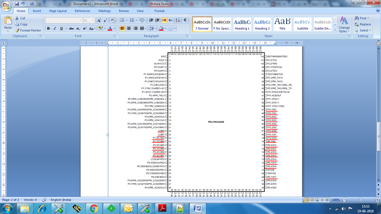
                  please find the given datasheet of the LCD connection with controller Msp430f67791A. Here red lines shows controller pin used for 8 mux lcd connection. This connection have 8 com of lcd & other S0 to S17 are segment of lcd. my problem of not display any segment is solved by making changes in pin configuration. here i have given ACLK clock direction & output on port pin 1.2 pf msp430f67791a as shown below. Before this pin was not given direction & output. so is it correct way to get display, the chnages donw by me in the TI's code is ok ? suggest me the correct way.

    /*
    P1.0 =
    P1.1 =
    P1.2 = ACLK
    P1.3 =
    P1.4 = MCLK
    P1.5 = SMCLK
    P1.6 =
    P1.7 =
    */

    #define P1DIR_INIT     (BIT2)
    #define P1SEL_INIT    (0)
    #define P1OUT_INIT   (BIT2)

    Regards,

    kinjal

  • Hi Kinjal,

    I am not sure why changing the direction and output value of that pin would change anything if it is not connected to the LCD, but that shouldn't cause any issues. If that has solved your issue, then I think it is a fine fix.

    Regards,
    Nathan

**Attention** This is a public forum