This thread has been locked.

If you have a related question, please click the "Ask a related question" button in the top right corner. The newly created question will be automatically linked to this question.

MSP430F5335: The problem of RTC_B Calendar feature

Part Number: MSP430F5335
Other Parts Discussed in Thread: MSP-FET

I am having an RTC_B problem with board which incorporates an MSP430F5335.  We have shipped around 800 of these boards with very little problems seen.  On rare occasions though, during production, we are seeing an issue where the RTC either doesn't increment (see the following thread started by me:  https://e2e.ti.com/support/microcontrollers/msp430/f/166/t/527645) or the RTC appears to increment by several years each second (see the following related link: https://e2e.ti.com/support/microcontrollers/msp430/f/166/t/675454?tisearch=e2e-sitesearch&keymatch=RTC_B).  It seems that the only way to correct the issue is to remove both DVCC and VBAT.  Removing DVCC only does not resolve the issue.  We have closely followed the recommended procedures described in the "Using the MSP430 RTC_B Module With Battery Backup Supply" application report SLAA665B.  In the past week, we have had 2 boards where the RTC doesn't increment and 2 where it incremented very quickly.  The second link above was handled offline so I could not follow it to the solution.  Is there anyway that someone could contact me to discuss the solution. Offline will be fine if necessary.

Thanks,

Greg

  • Hi Greg,

    Thanks for your detailed post.  mentioned that you reached out to him directly as well. Let me catch up with him and see if there are any updates on the second link that was pulled offline. Looking at the first thread, I'm concerned about the voltage spikes that could be exceeding the maximum input recommendations. In this thread, you mentioned that the issue is observed during production. Is there a chance that ESD is damaging these devices during handling or placement? Is there a chance that the MSP430F5335 is somehow getting back-powered by an I/O? If the issue is repeatable, it would be interesting to see if the device behaves the same way in our target socket board under the same conditions.

    Regards,

    James

  • James,

    Thank you for your help with this issue.  I am very interested in what may have solved the issue that was described in the second link above.  I would greatly appreciate if you could share that information with me.  

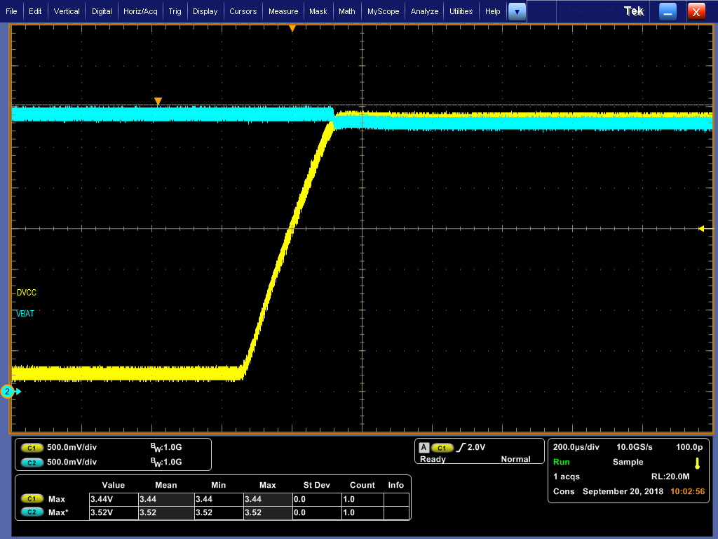
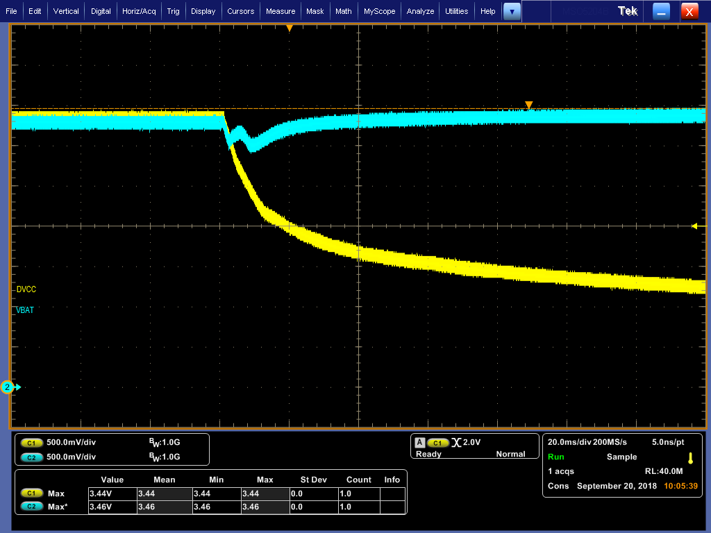
    I agree that voltage spikes are a great concern and we are definitely looking at ways to eliminate them totally.  Under normal operating conditions, we do not see any voltages that are close to being outside of acceptable ranges.  The attached files show VCC and VBAT when turning on and off the board with our power switch.

    This was captured from one of the boards that have experienced the problem.  The only time that we are seeing higher voltages is if we turn our power switch on and off repeatedly very quickly - the switching regulator that we are using seems to have a little more overshoot than desired in this situation.  If you have any suggestions for protective devices that will keep 3.3 volt lines from going above 4.1 volts (or 3.6 preferably) and also have extremely low leakage currents at 3.3 volts that would be wonderful.  It seems like most of the ones that will actually do the job have the snap back effect so once they trigger due to high voltage, the voltage has to drop below something like 2.8 volts before they release.  That is not acceptable on a VCC line of a battery operated device like ours - once triggered, the battery will be drained.

    I see in the spec sheet for the MSP430F5335 that the absolute maximum ratings for Vcc to Vss is 4.1 volts max.  Does this absolute max apply for AVCC, DVCC and VBAT?  VBAT is only listed under the Recommended Operating Conditions section which specifies 3.6 volts max.  I also see in the absolute max ratings where "Voltage applied to any pin (excluding VCORE, VBUS, V18) is Vcc + 0.3.  Would this apply to VBAT?

    In any case, we have not really seen any occurrences of this problem since my original post back in July 2016.  To the best of my knowledge, the 4 boards that we have seen the issue with over the past week were not subjected to having their power switch turned on and off rapidly.  With this in mind, most likely they were not subjected to overvoltage on any of their supply pins.  

    From our analysis, we have seen three distinct failure modes:

    1) From my original post in 2016, I saw three boards, all of which the real time clock time and date registers would not increment at all.  You could write values into them and they would hold, but never increment.  We confirmed that the hold bit was cleared.  It seemed like the 32KHz clock was just not making it to the RTC_B.

    2) Two boards that I have analyzed over the past few days showed that the time and date registers were incrementing very quickly like described in the second link above.  It appears as though the time and date registers were being clocked directly from the 32KHZ, like the prescalers were somehow bypassed.  The RTCRDYIFG interrupt was still triggering as I could see the time and date changing in my normal application although very quickly.  The time and date registers are only read into SRAM variables inside the RTCRDYIFG interrupt routine.

    3) Two other boards that I have analyzed over the past few days have appeared to have a frozen value for time and date from out application standpoint.  Looking at them closer shows that the time and date registers in the RTC were actually incrementing at a fast rate which appears to be directly driven from the 32KHz as described in 2 above.  The difference is that in this case, the RTCRDYIFG interrupt was not firing so the time and date SRAM variables in my application were not updating in the interrupt and therefore the date and time appeared to be frozen.  Further analysis showed that if the date and time was set in the MSP430, the RTCRDYIFG interrupt would fire one time afterward and allow my application SRAM variables to be updated one time only.  Interestingly, the time would be several minutes into the future from what time was actually being set.  This indicates that the time registers were being clocked at a fast rate (32KHz) during the time between setting the time and getting the one shot RTCRDY  interrupt.  Additionally I found that if I power cycle the board (VCC only, not VBAT), the date and time SRAM variables were zero initialized and would remain at all zeros afterward - no RTCRDYIFG interrupts were occurring.

    With all of these things in mind, this leads me to believe that there could be some undocumented registers in the MSP430 that may allow for testing modes to quickly increment the date and time registers for testing.  Is this the case?  Are there any other registers that I could look at to see if any of such modes may be inadvertently enabled?

    One other question that I have is how the RTC_B is reset on initial power up of VBAT.  We use an on-board 3.6 volt lithium battery to supply power to VBAT through 2 B140B series diodes to maintain the RTC when the main power is off.   We have a 2-pin jumper in series also which allows connecting/disconnecting this power.  The jumper is first installed once the board is completely assembled - therefore VBAT is powered up prior to VCC.  I am just wondering if there are additional test registers, when and how are they reset to the needed values for normal operation?

    In all cases (1,2,3) of this issue so far, if we simply remove the main power to the board (VCC) and also remove the jumper described in the previous paragraph (VBAT), then re-install the jumper and power up the board, the RTC works correctly and we never seen the problem again.  No similar problems have been reported from customers either.

    So far, we are focusing on the over voltage issues as the source of the problem, but we have not been able to reproduce any of the above 3 failure modes on demand.  If we could somehow repeat the problems, we could put measures in place to protect these voltages and be confident that we have found that actual cause.  Do you have any suggestions for repeating the problem?  Do you have any other information on undocumented registers that we may be able to use to gather more clues as to exactly what may be causing these issues?

    Thank you again for all of your assistance!

    Greg

  • Hi Greg,

    thanks for the valuable details this helps us a lot to make better judgements. However I still have some questions:

    1. When the RTC stopped or is jumping you mentioned a power cycle of the back-up domain (BOR) will bring it back to correct function right?
       Can you please try to do a PUC reset via WDT or something else to see if it's release the unexpected behavior as well?

    2. Is there a chance to provide some scope shots of DVCC and VBAT when you do the fast switching which will recreate it, might help us to reproduce this at TI.

    3. Is there the possbility that the device is doing write access to RTC registers when the power switching happens. Means can you sync up the RTC register write to a DVCC power down?

  • Thank you for taking the time to help with this!  Here are my responses:

    1) I have not been able to do extensive testing with how to exit the unexpected behavior condition since we have had only a limited quantity of boards exhibit it so far (3 back in 2016 and 6 over the past couple weeks).  Also, once we clear it, we have never been able to repeat on the same board or for that matter, any board on demand.  With that being said, here are the different ways that have appeared to clear the problem so far:

    a) Power cycling both VCC and VBAT

    b) I tried to change my code to add debugging to strobe a GPIO line on entry to RTCRDY interrupt.  When I flashed it into the MSP using  IAR EW430 and MSP-FET Flash Emulation Tool and ran the application, the problem was cleared - without cycling power to VBAT or VCC.

    c) I used our standard firmware feature which is part of our standard application to load new code into the MSP, this also corrected the problem.  This involves another processor communicating to the MSP430 over SPI to send the new firmware image and program it into flash bank 2.  Then a custom boot loader application is called which copies flash bank 2 to bank 0.  Then we use the following command to reset the MSP430:

       // Reset the MSP

       PMMCTL0 = PMMPW | PMMSWBOR;          // Generate a PMMSWBOR to reset the MSP

    This also cleared the RTC problem without cycling power to VBAT or VCC.

    d) In testing for voltage spikes on VCC and VBAT, I have done many tests turning our power switch on and off.  This switch turns on and off the gate of a FET which controls power being feed to a switching regulator (LT3971) which in turn powers VCC on the MSP430.  MSP430 VBAT is powered from the OUT pin on a MAX6361PUT31 Low-Power uP Supervisory IC which gets power on it's Vcc pin from the switching regulator and on it's VBATT pin from an on board 3.6 V lithium backup battery through 2 series diodes.  When turning the switch on and off at a normal rate, we never see any spikes as the previous scope shots showed.  When turning on and off very quickly, we have seen the switching regulator output overshot cause VCC and VBAT to go briefly to a maximum of about 4.24 volts on rare occurrences.  In the process of turning this switch on and off rapidly, I have been able to clear the RTC problem as well.  I have tried for many hours to duplicate causing the failure condition by turning on and off the switch but have not been able too.  As described previously, I have also tried using an external power supply connected through a software controlled FET to periodically add a voltage spike on VCC and VBAT to voltages > 5 volts.  I could never repeat the same RTC problem.  I am planning to set up a test for the weekend to software control the actual switch function and see if I can cause the failure condition.

    2) Below is a scope shot of the highest voltage on VCC and VBAT after about 20 minutes of turning the switch on and off as fast as I can.  Keep in mind, that I have never been able to recreate the problem condition by turning the switch on and off rapidly.  We have only theorized that this may be a potential cause of the problem  I have however been able to clear the problem doing this.  I certainly understand that we want to eliminate these spikes totally and we are attempting to come up with some changes to do so.  Also, under normal operation of the switch, the turn on and turn off of VCC and VBAT look to be within specifications.

    3) I will have to do some testing and studying to see if this could be happening but there are some things in place that would hopefully prevent it: 

    We initialize some RTC registers on boot up of course per application note "Using MSP430 RTC_B with Battery Backup Supply slaa665b".  We only read the date and time registers during the RTCRDY interrupt.  When setting the time in the RTC, we clear RTCRDYIE and set RTCHOLD in the RTCCTL01 register, update date time registers then clear RTCHOLD and set RTCRDYIE.  

    The reset output of MAX6361PUT31 uP Supervisor is connected to pin 96 (\RST/NMI/SBWTDIO) on the MSP430F5335 to provide a NMIIFG interrupt when VCC falls below aprox. 3.08 V however I had issues when trying to implement the interrupt.  Originally I tried to use the NMI interrupt to provide system protection and turn off power to our other processor on the board (LPC4350) when voltages get dangerously low.  From the code comments below you can see where I ran into issues in this attempt.  We have an additional voltage detector on the board that monitors the main supply voltage and pulls MSP430 P9.2 and P4.0 low if the main supply voltage is < 6V- should occur before VCC would see adverse effects. This is the mechanism currently in use for low voltage protection (besides SVS).  We have an interrupt enabled on P4.0 which monitors P9.2 and issues a PMMSWPOR reset if supply voltage recovers or remains in a loop if not - see code below.  This would hopefully prevent RTC accesses while voltage is low.

    #pragma vector = PORT4_VECTOR
    __interrupt void port4(void){
        uint16_t low_supply_msp_count;
        switch (__even_in_range(P4IV,0x10)) {
        case 0x00:             // No Interrupt
            break;
        case 0x02:             // P4.0 Interrupt, ORed status inputs from various sources
            // Check for LOW_SUPPLY_MSP and turn off power to LPC if Supply is low
            if ((P9IN & 0x4) == 0) {                // if LOW_SUPPLY_MSP is low
                LPC_POWER_OFF;                      // turn off the LPC4350
                LPC_POWER_DIR |= LPC_POWER_BIT;     // make LPC_POWER output to hold tight
                low_supply_msp_count = 0;
                while (low_supply_msp_count < 1000) {
                    if (P9IN & 0x4)
                        ++low_supply_msp_count;
                    else
                        low_supply_msp_count = 0;
                }
                // The power must have recovered so generate a reset to attempt to restart the system.
                PMMCTL0_H = 0xA5;
                PMMCTL0_L |= PMMSWPOR;
            }
            if ((P9IN & 0x10) == 0){                    // if Dig_Int low then
                sleep_flags |= TRIGGER_LPC_POWER_UP;    // trigger LPC power up
                LPM3_EXIT;                              // exit sleep mode
            }
            if ((P9IN & 0x20) == 0) {                   // if Exp_Din is active then
                sleep_flags |= TRIGGER_LPC_POWER_UP;    // trigger LPC power up
                LPM3_EXIT;                              // exit sleep mode
            }
            break; 
               
        case 0x04:             // P4.1 Interrupt       
            break; 
        case 0x06:             // P4.2 Interrupt       
            break; 
        case 0x08:             // P4.3 Interrupt       
            break; 
        case 0x0A:             // P4.4 Interrupt       
            break; 
        case 0x0C:             // P4.5 Interrupt       
            break; 
        case 0x0E:             // P4.6 Interrupt       
            break; 
        case 0x10:             // P4.7 Interrupt       
            break; 
           
        }
    } // end PORT4 vector

    This is our low_level_init function currently being used (see comments):

    int __low_level_init(void)

    {
      /* Insert your low-level initializations here */
       
        // Initialize Watchdog for 16 second timeout based on ACLK
        // At this point, XT1 and ACLK have not been initialized yet so the following will
        // actually select VLOCLK (10KHz) to feed the WDT.  The timeout is actually set to
        // aproximately 16 * 32768 / 10000 or 52.4 seconds.  As soon as ACLK is initialized, the WDT
        // will actually be set to a 16 second timeout.
        WDTCTL = WDTPW | WDTIS__512K | WDTCNTCL | WDTSSEL__ACLK;  
       
        // Turn off the LPC_CTL line as quickly as possible on boot up to keep LPC4350 powered down until ready.
        P6OUT = 0x80;   // 3-5 = low; 6-7 = high to for MVT off and LPC off     
        P6SEL = 0x07;   // 0-2 = AI; 3-7 = GPIO
        P6DIR = 0xF8;   // all GPIO are outputs
       
        // Configure RST/NMI for NMI, with pullup and interupt on falling edge quickly on boot up.
        // This is done so that the RST input will not cause an actual reset if GLOBAL_RESET pulls low.  We will rely on the
        // brown-out and SVS reset mechanisms to reset the processor as well as P4.0 GPIO low supply interrupt.
        // We need to do this because we must rely on SVS to switch to the backup power system in order for the MSP RTC to maintain
        // time when the power is removed from the board.  If a RST occurs first, then the RTCHOLD flag in RTCCTL1 will be set to its
        // default value of 1 which stops the RTC.
        SFRRPCR = SYSRSTRE | SYSRSTUP | SYSNMIIES | SYSNMI;
       
        // An attempt was made to use the NMI interrupt to handle powering down the LPC processor when power is removed from the board (GLOBAL_RESET goes low)
        // This caused the processor to go off in the weeds at times during quick turn off/on of the power supply.
        // We may be able to fix with adjustments to the brown out detection or other settings, maybe watchdog.  Testing needed.
        // For now, the PORT4 interrupt is used to trigger resets on LOW_SUPPLY_MSP voltage detector input
    //    SFRIFG1 &= ~NMIIFG;     // clear the NMI interrupt flag
    //    SFRIE1 |= NMIIE;        // enable the NMI interrupt
       
        log_reset_cause();
       
      /*
       * Return value:
       *
       *  1 - Perform data segment initialization.
       *  0 - Skip data segment initialization.
       */

      return 1;
    }

    The following is the NMI interrupt implementation that was last tested but caused issues as described in the comments above.

    THE NMI INTERRUPT IS NOT CURRENTLY ENABLED SINCE CODE IS COMMENTED OUT ABOVE.

    #pragma vector = UNMI_VECTOR

    __interrupt void unmi(void) {
        uint16_t low_supply_msp_count;
        INT_DEBUG_LOG(2);
        switch(__even_in_range(SYSUNIV, 0x08)) {
        case 0x00: // No Interrupt
            break;
        case 0x02: // NMIIFG Interrupt Pending
            // Check for LOW_SUPPLY_MSP and turn off power to LPC if Supply is low
            if ((P9IN & 0x4) == 0) {                // if LOW_SUPPLY_MSP is low
                LPC_POWER_OFF;                      // turn off the LPC4350
                LPC_POWER_DIR |= LPC_POWER_BIT;     // make LPC_POWER output to hold tight
                low_supply_msp_count = 0;
                while (low_supply_msp_count < 1000) {
                    if (P9IN & 0x4)
                        ++low_supply_msp_count;
                    else
                        low_supply_msp_count = 0;
                }
                // The power must have recovered so generate a reset to attempt to restart the system.
                PMMCTL0_H = 0xA5;
                PMMCTL0_L |= PMMSWPOR;
            }
            break;
        case 0x04: // OFIFG Interrupt Pending
            break;
        case 0x06: // ACCVIFG Interrupt Pending
            break;
        case 0x08: // BUSIFG Interrupt Pending
            break;
        }
    }

    Some questions for you: 

    1) As mentioned previously, are there any undocumented registers for enabling test modes for the RTC_B? 

    2) I have only one board that is still in the unexpected mode.  This one doesn't seem to ever update any of the RTC registers on its own and the RTCRDY interrupt is not occurring.  I can issue a command to synchronize the time and it is successfully written to the RTC date time registers.  The new time can then be read back from the registers but they never increment.  Is there anything else you would want me to check on this board before attempting to clear the problem???  It may or may not occur for another few years...

    Thanks,

    Greg

  • Greg,

    thanks! Regardign your quesitons we will contact you offline.
  • Dietmar,

    Thank you very much. I will await your email or call. Please let me know if you need anything else. We are very anxious to understand what is going on with this issue.

    Thanks,
    Greg
  • Hello,

    To update the E2E community, this issue is still under investigation. When complete, we'll summarize the solution.

    Regards,

    James

**Attention** This is a public forum