This thread has been locked.

If you have a related question, please click the "Ask a related question" button in the top right corner. The newly created question will be automatically linked to this question.

MSP430F5359: External crystal XT1 is not working properly

Expert 1165 points
Part Number: MSP430F5359

Hello, I'm trying to use MSP430f5359 for my project but the crystal oscillator is not working, i downloaded the code from resource explorer for msp430f5359 to test it but its still not working. Attach here is the circuit of crystal oscillator.

what am i doing wrong?

  • Hello Kary,

    Are you using a custom board? If so, have you provided the correct effective load capacitance for the 32.768kHz crystal you've selected for XT1? Please don't measure the crystal using an oscilloscope probe at the crystal. Instead, use one of the XT1 code examples to output the clock via the ACLK pin.

    You can find more information about using the 32kHz external crystal in the MSP430 32-kHz Crystal Oscillators app note. Also, I would recommend searching for answers here on the forum. Others have had the same issue, so there will be valuable advice on what to check and fix.

    Regards,

    James

  •  As there is no custom board for msp430f5359 , i designed on my own.  I have  provided the correct effective load capacitance for the 32.768kHz crystal. I used RTC_B in real time clock mode example from resource explorer to test it. Here is the link of code example :

    And attach here is the circuit i used:

  • kary said:
    As there is no custom board for msp430f5359 , i designed on my own.

    Here, custom board means anything other than one of our development or target boards. Now I know you're using your own custom board.

    I see the RTC code example uses the internal load capacitors for the crystal. Are you using external load caps too (I see they're DNP in your schematic but wanted to check)? Did you follow the equations in Section 2.1 in SLAA322 to correctly calculate the effective load capacitance? Did you follow the layout guidelines in SLAA322? Things like traces routed underneath the crystal can cause crystal drop-out.

    When you say "it's not working", can you be more specific? Is the code getting stuck somewhere specifically, such as where the code checks for the XT1 oscillator fault flag?

    Regards,

    James

  • My crystal oscillator is oscillating on approx 27KHZ,  i didn't use  ernal load caps and attach is the hardware. what could be the problem?

  • I tried this code:

    #include <msp430.h>

    int main(void)
    {
    WDTCTL = WDTPW | WDTHOLD; // Stop WDT
    while(BAKCTL & LOCKBAK) // Unlock XT1 pins for operation
    BAKCTL &= ~(LOCKBAK);
    UCSCTL6 &= ~(XT1OFF); // XT1 On
    UCSCTL6 |= XCAP_3; // Internal load cap
    // Loop until XT1 fault flag is cleared
    do
    {
    UCSCTL7 &= ~(XT2OFFG | XT1LFOFFG | DCOFFG);
    // Clear XT2,XT1,DCO fault flags
    SFRIFG1 &= ~OFIFG; // Clear fault flags
    }while (SFRIFG1&OFIFG); // Test oscillator fault flag

    P1DIR |= 0x01; // P1.0 output
    TA1CCTL0 = CCIE; // CCR0 interrupt enabled
    TA1CCR0 = 1000-1;
    TA1CTL = TASSEL_1 | MC_1 | TACLR; // ACLK, upmode, clear TAR

    __bis_SR_register(LPM3_bits | GIE); // Enter LPM3, enable interrupts
    __no_operation(); // For debugger
    }

    // Timer1 A0 interrupt service routine
    #if defined(__TI_COMPILER_VERSION__) || defined(__IAR_SYSTEMS_ICC__)
    #pragma vector=TIMER1_A0_VECTOR
    __interrupt void TIMER1_A0_ISR(void)
    #elif defined(__GNUC__)
    void __attribute__ ((interrupt(TIMER1_A0_VECTOR))) TIMER1_A0_ISR (void)
    #else
    #error Compiler not supported!
    #endif
    {
    P1OUT ^= 0x01; // Toggle P1.0
    }

    the result was Led is not blinking and again i tired the same code removing the crystal part the LED was blinking. what could be the problem the circuit?

  • Kary:

    XT1 won't operate unless you do some magic with regard to the Battery
    Backup Subsystem. (This isn't entirely clear in the documentation.)

    Here are the notes I embedded in our source code when I discovered this:

    * o The unlocking of the Battery Backup Subsystem isn't described
    * in any of the TI documentation or sample code as being required
    * but programming the XT1 oscillator or its bypass mode certainly
    * doesn't work if you don't do this.
    *
    * See:
    *
    * o e2e.ti.com/.../683218
    *
    * o e2e.ti.com/.../1682900
    *
    *
    * o Other notes on that website describe there being a counter
    * (also undocumented) that must count 8192 non-faulted clock
    * cycles before an "Oscillator Fault" can be cleared. For the
    * 32,768 Hz XT1, that means that it takes 1/4 second to recognize
    * that an "Oscillator Fault" has cleared. 'Scope measurements
    * confirm this; the fault-clearing loop runs for 250 ms.

    I hope this helps you!

  • i didn't get this , can you provide me a sample code that works? I don't know what i am doing wrong but i couldn't make it work from the attached reference.
  • Part Number: MSP430F5359

    Tool/software: Code Composer Studio

    I was trying to run this code but its not working:

    #include <msp430.h>

    int main(void)
    {
    WDTCTL = WDTPW | WDTHOLD; // Stop WDT
    while(BAKCTL & LOCKBAK) // Unlock XT1 pins for operation
    BAKCTL &= ~(LOCKBAK);
    UCSCTL6 &= ~(XT1OFF); // XT1 On
    UCSCTL6 |= XCAP_3; // Internal load cap
    // Loop until XT1 fault flag is cleared
    do
    {
    UCSCTL7 &= ~(XT2OFFG | XT1LFOFFG | DCOFFG);
    // Clear XT2,XT1,DCO fault flags
    SFRIFG1 &= ~OFIFG; // Clear fault flags
    }while (SFRIFG1&OFIFG); // Test oscillator fault flag

    P1DIR |= 0x01; // P1.0 output
    TA1CCTL0 = CCIE; // CCR0 interrupt enabled
    TA1CCR0 = 1000-1;
    TA1CTL = TASSEL_1 | MC_1 | TACLR; // ACLK, upmode, clear TAR

    __bis_SR_register(LPM3_bits | GIE); // Enter LPM3, enable interrupts
    __no_operation(); // For debugger
    }

    // Timer1 A0 interrupt service routine
    #if defined(__TI_COMPILER_VERSION__) || defined(__IAR_SYSTEMS_ICC__)
    #pragma vector=TIMER1_A0_VECTOR
    __interrupt void TIMER1_A0_ISR(void)
    #elif defined(__GNUC__)
    void __attribute__ ((interrupt(TIMER1_A0_VECTOR))) TIMER1_A0_ISR (void)
    #else
    #error Compiler not supported!
    #endif
    {
    P1OUT ^= 0x01; // Toggle P1.0
    }

     what could be the problem? can you please fix this?

  • Hi Kary,

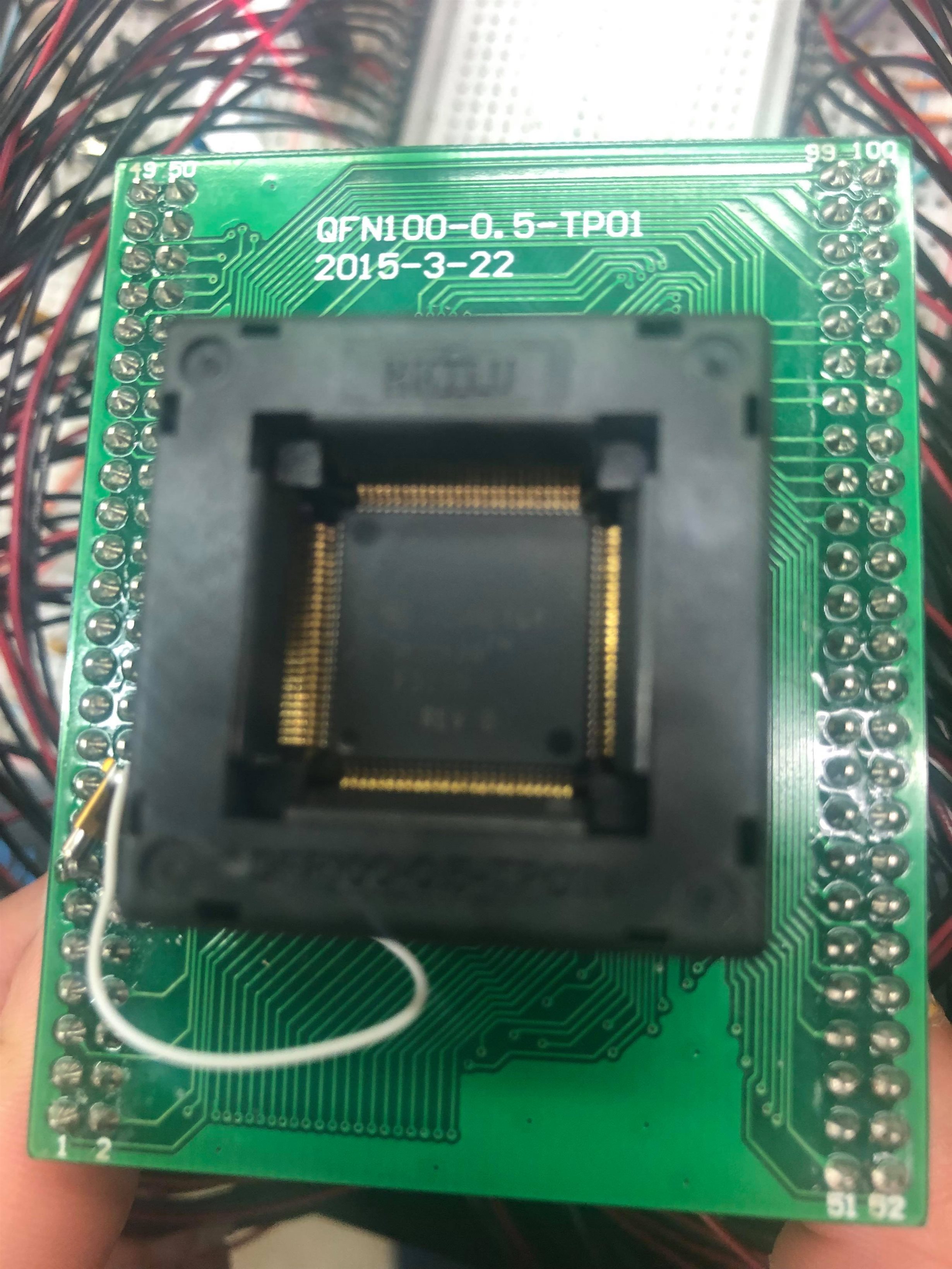
    In the code you shared, if there's an oscillator fault flag, it won't continue to the part of code that toggles the LED. Looking at the picture you shared, how you've soldered the crystal to the target board isn't how we recommend doing it. Since you're observing a frequency of ~27kHz, there's something affecting the crystal, and I'm suspecting it's related to the hardware, not software.

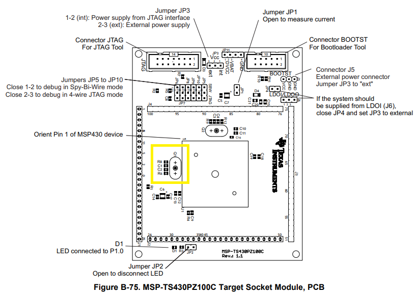
    Since you're using the MSP430F5359, I'm assuming the target board shown in your picture is the MSP-TS430PZ100C. Is there a specific reason why you couldn't solder the XT1 crystal at the Q1 location on the target board rather than soldering it underneath the headers?

    Regards,

    James

  • The board has no place to mount on Q1 postion. when i execute the previous  code, the led lights up but it's not blinking.

  • kary said:
    The board has no place to mount on Q1 postion. when i execute the previous  code, the led lights up but it's not blinking.

    I see. Unfortunately, this board is not our target board, so it will be challenging to test your crystal using this board, especially since the crystal is so far from the MCU, the large amounts of solder will affect the capacitance as well as the long jumper wire, etc. You may not be able to get past the oscillator fault flag using this hardware.

    Regards,

    James

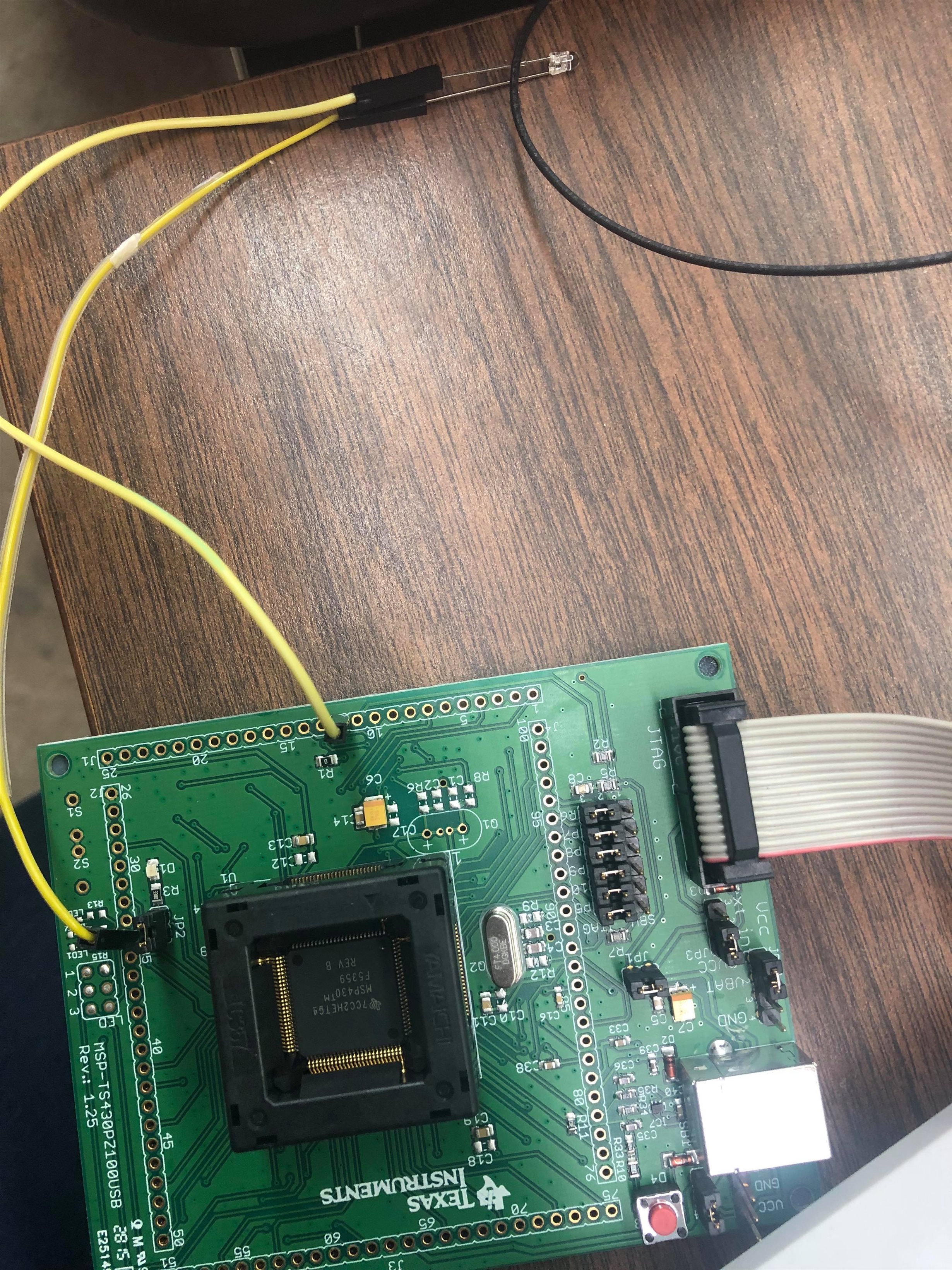
  • Just got TI board shipped and i couldn't pass oscillator fault not even in this hardware. Attach here is the hardware  and the code i tried from resource explorer.

    #include <msp430.h>

    int main(void)
    {
    WDTCTL = WDTPW | WDTHOLD; // Stop WDT
    while(BAKCTL & LOCKBAK) // Unlock XT1 pins for operation
    BAKCTL &= ~(LOCKBAK);
    UCSCTL6 &= ~(XT1OFF); // XT1 On
    UCSCTL6 |= XCAP_3 | XT1BYPASS; // Internal load cap UCSCTL3 = 0;
    // XT1 sourced from external clock signal
    // Loop until XT1,XT2 & DCO stabilizes - In this case loop until XT1 and DCo settle
    do
    {
    UCSCTL7 &= ~(XT2OFFG | XT1LFOFFG | XT1HFOFFG | DCOFFG);
    // Clear XT2,XT1,DCO fault flags
    SFRIFG1 &= ~OFIFG; // Clear fault flags
    }while (SFRIFG1&OFIFG); // Test oscillator fault flag

    UCSCTL6 &= ~(XT1DRIVE_3); // Xtal is now stable, reduce drive strength

    P1DIR |= 0x01; // P1.0 output
    TA1CCTL0 = CCIE; // CCR0 interrupt enabled
    TA1CCR0 = 1000-1;
    TA1CTL = TASSEL_1 | MC_1 | TACLR; // ACLK, upmode, clear TAR

    __bis_SR_register(LPM3_bits | GIE); // Enter LPM3, enable interrupts
    __no_operation(); // For debugger
    }

    // Timer1 A0 interrupt service routine
    #if defined(__TI_COMPILER_VERSION__) || defined(__IAR_SYSTEMS_ICC__)
    #pragma vector=TIMER1_A0_VECTOR
    __interrupt void TIMER1_A0_ISR(void)
    #elif defined(__GNUC__)
    void __attribute__ ((interrupt(TIMER1_A0_VECTOR))) TIMER1_A0_ISR (void)
    #else
    #error Compiler not supported!
    #endif
    {
    P1OUT ^= 0x01; // Toggle P1.0
    }

  • Hi Kary,

    When you post code, it's much more readable when posted to the forum using the Syntax Highlighter tool (looks like "</>") found under the "Insert Code, Attach Files and more..." link shown after you click the "Reply" button.

    UCSCTL6 |= XCAP_3 | XT1BYPASS; // Internal load cap UCSCTL3 = 0;

    Why are you setting XT1BYPASS while trying to use an external crystal? This is probably why you're seeing an oscillator fault because it disables the XT1 module.

    kary said:
    Attach here is the hardware  and the code i tried from resource explorer.

    That's great to see. However, I'm not sure why you haven't soldered the crystal to the through holes on the board at Q1. I'm not sure which example or examples you've copied, since you didn't specify that.

    Please try running the following code example to see if you can get past the oscillator fault.

    msp430f665x_ucs_06.c

    /* --COPYRIGHT--,BSD_EX
     * Copyright (c) 2012, Texas Instruments Incorporated
     * All rights reserved.
     *
     * Redistribution and use in source and binary forms, with or without
     * modification, are permitted provided that the following conditions
     * are met:
     *
     * *  Redistributions of source code must retain the above copyright
     *    notice, this list of conditions and the following disclaimer.
     *
     * *  Redistributions in binary form must reproduce the above copyright
     *    notice, this list of conditions and the following disclaimer in the
     *    documentation and/or other materials provided with the distribution.
     *
     * *  Neither the name of Texas Instruments Incorporated nor the names of
     *    its contributors may be used to endorse or promote products derived
     *    from this software without specific prior written permission.
     *
     * THIS SOFTWARE IS PROVIDED BY THE COPYRIGHT HOLDERS AND CONTRIBUTORS "AS IS"
     * AND ANY EXPRESS OR IMPLIED WARRANTIES, INCLUDING, BUT NOT LIMITED TO,
     * THE IMPLIED WARRANTIES OF MERCHANTABILITY AND FITNESS FOR A PARTICULAR
     * PURPOSE ARE DISCLAIMED. IN NO EVENT SHALL THE COPYRIGHT OWNER OR
     * CONTRIBUTORS BE LIABLE FOR ANY DIRECT, INDIRECT, INCIDENTAL, SPECIAL,
     * EXEMPLARY, OR CONSEQUENTIAL DAMAGES (INCLUDING, BUT NOT LIMITED TO,
     * PROCUREMENT OF SUBSTITUTE GOODS OR SERVICES; LOSS OF USE, DATA, OR PROFITS;
     * OR BUSINESS INTERRUPTION) HOWEVER CAUSED AND ON ANY THEORY OF LIABILITY,
     * WHETHER IN CONTRACT, STRICT LIABILITY, OR TORT (INCLUDING NEGLIGENCE OR
     * OTHERWISE) ARISING IN ANY WAY OUT OF THE USE OF THIS SOFTWARE,
     * EVEN IF ADVISED OF THE POSSIBILITY OF SUCH DAMAGE.
     *
     *******************************************************************************
     * 
     *                       MSP430 CODE EXAMPLE DISCLAIMER
     *
     * MSP430 code examples are self-contained low-level programs that typically
     * demonstrate a single peripheral function or device feature in a highly
     * concise manner. For this the code may rely on the device's power-on default
     * register values and settings such as the clock configuration and care must
     * be taken when combining code from several examples to avoid potential side
     * effects. Also see www.ti.com/grace for a GUI- and www.ti.com/msp430ware
     * for an API functional library-approach to peripheral configuration.
     *
     * --/COPYRIGHT--*/
    //******************************************************************************
    //  MSP430F665x Demo - XT1 sources ACLK
    //
    //  Description: This program demonstrates using XT1 to source ACLK
    //  ACLK = LFXT1 = 32,768Hz	
    //  //* An external watch crystal between XIN & XOUT is required for ACLK *//	
    //
    //               MSP430F665x
    //             -----------------
    //        /|\ |              XIN|-
    //         |  |                 | 32kHz
    //         ---|RST          XOUT|-
    //            |                 |
    //            |             P1.0|-->ACLK = ~32kHz
    //            |                 |
    //
    //   P. Thanigai
    //   Texas Instruments Inc.
    //   October 2012
    //   Built with IAR Embedded Workbench Version: 5.40 & CCS V5.2
    //******************************************************************************
    #include <msp430.h>
    
    int main(void)
    {
      WDTCTL = WDTPW | WDTHOLD;                 // Stop watchdog timer
    
      P1DIR |= BIT0;                            // ACLK set out to pin
      P1SEL |= BIT0;
      P5SEL |= BIT4+BIT5;                       // Select XT1
    
      while(BAKCTL & LOCKBAK)                   // Unlock XT1 pins for operation
         BAKCTL &= ~(LOCKBAK);
      UCSCTL6 &= ~(XT1OFF);                     // XT1 On
      UCSCTL6 |= XCAP_3;                        // Internal load cap 
      // Loop until XT1 fault flag is cleared
      do
      {
        UCSCTL7 &= ~(XT2OFFG | XT1LFOFFG | DCOFFG);
                                                // Clear XT2,XT1,DCO fault flags
        SFRIFG1 &= ~OFIFG;                      // Clear fault flags
      }while (SFRIFG1&OFIFG);                   // Test oscillator fault flag
      
      UCSCTL6 &= ~(XT1DRIVE_3);                 // Xtal is now stable, reduce drive strength
    
      UCSCTL4 |= SELA_0;                        // ACLK = LFTX1 (by default)
      
      __bis_SR_register(LPM3_bits);             // Enter LPM3
      __no_operation();                         // For debugger
    }

    Regards,

    James

  • yes, it did pass the oscillator fault and i placed crystal in Q1 too. i was about to use PWM for my device using xtal. can you suggest me any code for that?
    i didn't understand this line though:

    P5SEL |= BIT4+BIT5; // Select XT1

    there is nothing in 5.4 and 5.5 in msp430f5359. 

  • kary said:
    yes, it did pass the oscillator fault and i placed crystal in Q1 too.

    Great!

    kary said:
    i was about to use PWM for my device using xtal. can you suggest me any code for that?

    Please search the forum or create a new post for this question.

    kary said:

    P5SEL |= BIT4+BIT5; // Select XT1

    there is nothing in 5.4 and 5.5 in msp430f5359

    For the MSP430F665x devices, they don't have dedicated XT1 pins like the MSP430F5359. Thus, this line of code is necessary to configure the pins for the XT1 functionality on the F665x devices, but not the F5359 device (since it has dedicated XT1 pins).

    Regards,

    James

**Attention** This is a public forum