This thread has been locked.

If you have a related question, please click the "Ask a related question" button in the top right corner. The newly created question will be automatically linked to this question.

Compiler/MSP430F2619: MSP430F2619 USB to Serial Programming Issue

Part Number: MSP430F2619

Tool/software: TI C/C++ Compiler

Hello TI,

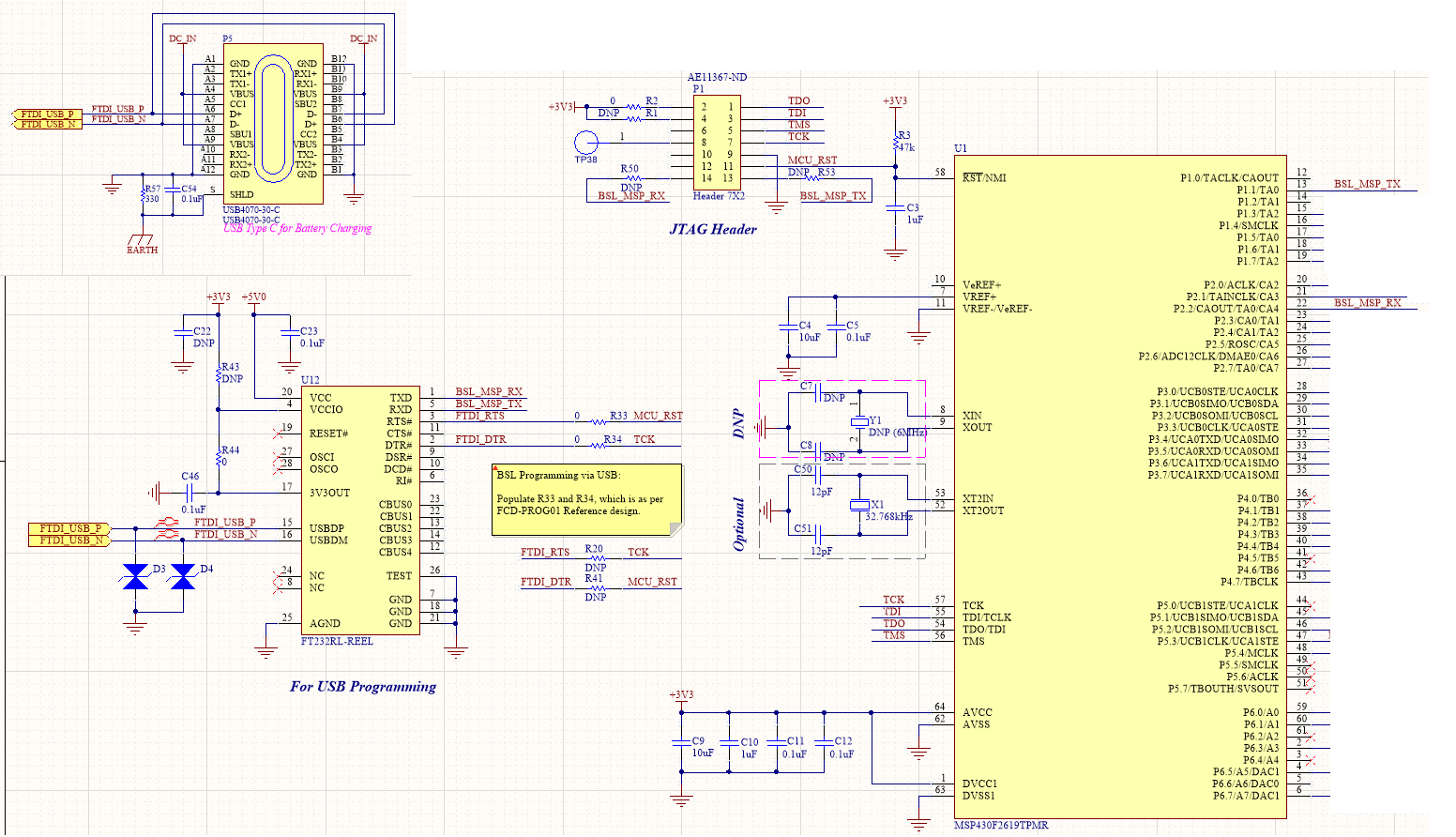
We are using MSP430F2619 and in order to programmer it via USB we have added the UART to Serial converter, FT232RL (circuit snapshot is attached below).

We are using TI bootloader with demo code. We can see the PORT coming up briefly on PC and then it resets. We are not sure why this is not stable. USB signals are routed properly in differential manner with short traces. We have tried to swap the resistors R33, R20 & R34, R41 but it is also not helping. Can you please review the circuit diagram and suggest if anything that we can do on it?

I will be looking to your kind reply.

Thanks,

Muhammad Awais

  • Hi Muhammad,

    After reviewing your schematic, I found that you seems are using C3/1uF capacitance for the RST pin decoupling. TI recommend to use less than 2nF capacitance.

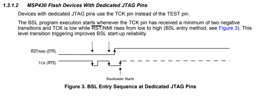
    Also, since you are using BSL method for the programming, according to the BSL User's Guide (SLAU319), you can find that R20&R41 configuration is correct. Shown as below.

    Let me know if this helps.

    Regards,

    Harry

  • Hi Harry,

    Thanks for your reply.

    Changing the caps still not helping (we are using R20&R41).

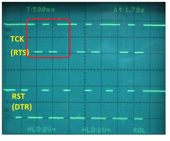
    We have checked the TCK and RST lines on oscilloscope. It seems like TCK is generating the sequence to initialize BSL mode but RST is not pulled-down, assuming RST must be pulled low by DRT as BSL sequence will be initialize by PC.

    Do you think NMI is doing this? It seems like on power ON the RST is high but then pulled low (must be due to DTR) but again pulled high. 

    Kind regards,

    Muhammad Awais

  • Harry,

    I was reading in the document (slau319u) that if the TCK and TMS pins are left floating, the device can unintentionally enter JTAG mode. You can see in our schematic that both TCK and TMS are floating and do you think this may be the case of pulling back RST pin to High?

    We didn't try yet to add pull-up resistor and pull-down cap on TCK and TMS.


    Kind regards,

    Muhammad Awais
  • Hi Muhammad,

    For the waveform you post here, I still have not much clue. Let me take some time for it.

    Besides, I have several questions for you:
    1. I noticed that the resister R43 is marked as DNP. Do you populate this resistor? If not, how do you power up the MSP430?
    2. Does the port still coming up briefly and the disappear?
    3. If the port is stable in your PC terminal, do you do some simple test to see if FT232 works well? Since you have a full JTAG interface in your board, could you please download a UART loopback program via JTAG and to see if the FT232 (USB-UART) works well?

    As for your latest question, it's not necessary to add pullup resistor and pulldown capacitor since F2619 is not a shared-JTAG device. It's JTAG are dedicated pins. I believe the pullup and pulldown RC component is required for a shared-JTAG device.
    Let me know if you have some update.

    Regards,
    Harry
  • Hello Harry,

    Below are answers to your questions;

    1. Yes it is not populated because U12 internally generates 3.3V so in this case we don't need this. Voltage on pin 17 and hence pin 4 is 3.4V.
    2. When we plug the board in to the PC with the power off, no COM port appears. If you power-up the board (connect the battery and press the button to turn it on) then COM4 appears on the list and an FTDI driver is loaded for that COM port. The COM port stays there until the USB lead is removed or the power is turned off.
    3. We are going to check this.

    Please let me know if you will come up with some other suggestion/solution.


    Thanks,

    Muhammad Awais
  • Hi Muhammad,

    I can't come up much more things. Just one thing, where does the '+5V0' network in your schematic come from? Is it from the Type-C interface via some button? Since in my experience with FT232, I always directly connected the #20 pin to the USB DVCC.
    Please try the simple test I mentioned before to make sure at least FT232 works well. Let me know your updates.

    Regards,
    Harry
  • Hi Harry,

    We are using USB power to charge the battery. Battery output is used to boost 5V for this U12 and other circuity. I didn't power it directly from USB power because we are not applying USB power all the time.

    I will get back to you after testing the FT232 in loopback.


    Thanks,

    Muhammad Awais
  • Are you using BSLDEMO for flashing?  If so, I believe the polarity of both DTR and RTS may be the opposite of what you need for the F2619 BSL using the FT adapter.   You can test this by plugging in ONLY the FT adapter, then running BSLDEMO, and checking what shows up on your scope on DTR and RTS coming out of the adapter.  When I did that, I found that the DTR line was the opposite of the polarity shown in Figure 2 and Figure 3 of slau319, and the RTS line was the same as Figure 2, which would be the opposite of what you need, which is Figure 3.

    I recompiled a version of BSLDEMO with the added options -i and -j to individually invert the polarity of DTR and RTS.  You might want to try the four possible combinations to see if one of them will work.  If none of them work, then the problem is something else.  My version is here:

    https://github.com/gbhug5a/MSP430-BSL/tree/master/BSLDEMO-2.01c

    If you aren't using BSLDEMO, well, nevermind.

  • Hi Muhammad,

    Have you tried the loopback test for FT232? Any other update from your side?

    Regards,
    Harry
  • Hello Harry and George,

    @ George: Thanks for your comment on it.
    @ Harry: Our embedded guys are working on all the options. I will let you guys know about the update.


    Kind regards,

    Muhammad Awais
  • Hi Harry,

    We have tried the serial and it is working fine. The only issue is that we are unable to enter BSL Mode and we are expecting that it is most probably due to the DTR and RTS due to which it is unable to enter in BSL mode. 

    Kind regards,

    Muhammad Awais

  • Hi Muhammad,

    Really sorry that I don't have F2619/FT232 in hand right now. I can't do much test from my side.
    Do you use "BSLDEMO2.exe" for you application?
    If so, could you please test the DTR/RTS signal without the F2619 firstly to see if the polarity is correct, just as George said?
    The purpose is to make sure if the DTR/RTS timing sequence matches the BSL entry requirement.
    Let me know if you have updates.
    Ps, really sorry for taking such long time for this issue.

    Regards,
    Harry
  • Hello Harry and George,

    Sorry for being late on testing this all. We have checked the  FT232, this seems working fine. So there is no issue at least on FT232.

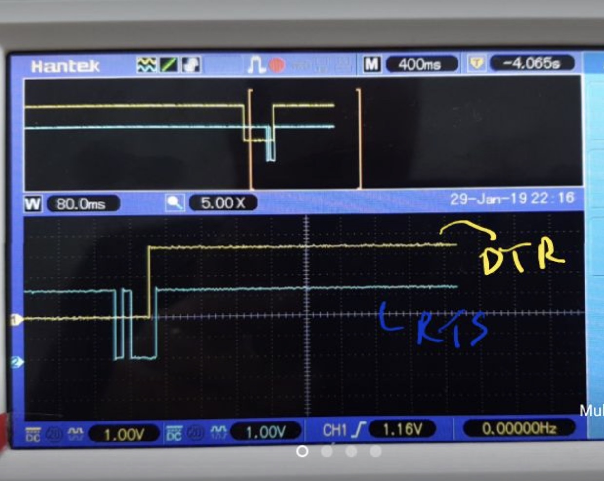
    DTR/RTS polarity looked wrong. It is fixed now, so the right bootloader entry sequence is sent. Now we are getting a synchronisation error which means that the TX/RX is wrong some how. We tried flipping the bits of the synch character and still got an error.

    Seems like  TX and RX also are ok.  0x80 was sent to the MSP430  but it is not responded to anything. We can set up our user program to look at the pin the 0x80 should arrive on an it sees it, which means the MCU hasn't gone into BSL mode.

    Few things we tried in coding as given below;

       //IE1 &= ~NMIIE; // disable NMI so BSL and USB work OK // FIXME doesn't work

       //IE1 |= NMIIE; // enable NMI so BSL and USB work OK // FIXME doesn't work

       // default should be set for RST so no action required here

       //WDTCTL &= ~WDTNMI; // setup #RST/NMI to act as reset, set bit 5 to 0

       //WDTCTL |= WDTNMI; // setup #RST/NMI to act as NMI, set bit 5 to 1

    None of them worked. We are using the default WDTNMI which is 0 right now - which should work!

    Please let us know if you think anything goes wrong on MSP side? So everything on the board is fine even the TX and RX that is for BSL except entering into BSL mode.

    Kind regards,

    Muhammad Awais

  • Muhammad,

    Could you please let me know the time scale of the oscilloscope screenshot?

    Besides, I could throw up something you may want to double check:
    1. Could you please double check the RST & TCK connection (RST should be the yellow signal, TCK the blue)?
    2. Monitor the TX/RX signal to see if the signal integrity is good.

    Plus, it's not necessary to do the test in your application code, since if it enters the BSL well, your application code won't work.
    Let me know your update.

    Regards,
    Harry
  • Hi Muhammad,

    Shall I close this thread since the entry issue is solved and some of the posts are also useful for others in the forum.
    If you still have problem, could you please make a new post for it?
    Thanks a lot.

    Regards,
    Harry

**Attention** This is a public forum