This thread has been locked.

If you have a related question, please click the "Ask a related question" button in the top right corner. The newly created question will be automatically linked to this question.

CCS/MSP430G2553: 4 Digit 7 Segment Clock

Part Number: MSP430G2553
Other Parts Discussed in Thread: ENERGIA

Tool/software: Code Composer Studio

Hello!

I have a trouble with my MSP.

Display's kathodes have direct connection to uC. Only Anodes have resistors.|
Problem: Timer doesn't count.

After upload a soft, there are four digits with all leds on (except dots) - there are four eights like : 8 8 8 8.
Nothing happened at all.

Under Debug session I can see, that program stops on while(1)...
I was trying many different codes, but still no effect.
I have no warnings at all, no troubles, no problems.

What is wrong with code?

Thanks in advance for help.

DETAILS:
Connection (Common anodes A-5649 display) looks like:

P1.0 - segm. A
P1.1 - segm. B
P1.2 - segm. C
P1.3 - Button - useless now...
P1.4 - segm. D
P1.5 - segm. E
P1.6 - segm. F
P1.7 - segm. G

P2.0 - Digit 0    //via resistor 220 ohm
P2.1 - Digit 1    //via resistor 220 ohm
P2.2 - Digit 2    //via resistor 220 ohm
P2.3 - Digit 3    //via resistor 220 ohm
P2.4 - segm. DP

CODE:

#include <msp430.h>

#define a 0x01           //00 0000 0000 0001
#define b 0x02           //00 0000 0000 0010
#define c 0x04           //00 0000 0000 0100
#define d 0x10           //00 0000 0000 1000
#define e 0x20           //00 0000 0001 0000
#define f 0x40           //00 0000 0010 0000
#define g 0x80           //00 0001 0000 0000
#define Dig_1  0x01   //P2.0
#define Dig_2  0x02   //P2.1
#define Dig_3  0x04   //P2.2
#define Dig_4  0x08   //P2.3
#define DP     0x10   //P2.4
//#define S2     0x20   //Button 2 P2.5
//#define S1     0x03   //Button 1 P1.3

int display_min[]={a+b+c+d+e+f, b+c, a+b+d+e+g, a+b+c+d+g, b+c+f+g, a+c+d+f+g, a+c+d+e+f+g, a+b+c, a+b+c+d+e+f+g, a+b+c+d+f+g};
int display_hour[]={a+b+c+d+e+f, b+c, a+b+d+e+g, a+b+c+d+g, b+c+f+g, a+c+d+f+g, a+c+d+e+f+g, a+b+c, a+b+c+d+e+f+g, a+b+c+d+f+g};

//clock variables
volatile unsigned int j;
volatile unsigned int TI_second = 0;
volatile unsigned int TI_minute = 0;
volatile unsigned int TI_hour = 0;
volatile unsigned int LoopCtr1;
volatile unsigned int dig_num = 0;
unsigned int flag_dp = 0x01;

void Get_time(void)
    {
       j++;
      if (j==20)   //50mS * 20 = 1sec.
        {
          j=0;
         // P2OUT ^= DP;
          TI_second++;

          flag_dp = 1;
          if (TI_second==60)
            {
              TI_second = 0;
              TI_minute++;

              if (TI_minute==60)
               {
                 TI_minute = 0;
                 TI_hour++;

                if (TI_hour==24)
                  {
                    TI_hour = 0;
                  }
               }
            }
        }
    }


void Display_time(void)
    {
      switch( dig_num )
      {
        case 0:
          {
            P1OUT = display_min[TI_minute/10];    //load first digit for minutes
            P2OUT |= BIT0;   //set   dig#0
            P2OUT &= ~0x0E;  //clear dig#1, 2, 3
            dig_num = 1;
          }
          break;
		  
       case 1:
         {
			P1OUT = display_min[TI_minute%10];    //load second digit for minutes
			P2OUT |= BIT1;   //set dig#1
			P2OUT &= ~0x0D;  //clear dig#0, 2, 3
                if(flag_dp == 1)
					{
						flag_dp = 0;
						P2OUT ^= DP;
					}

			dig_num = 2;
         }
         break;

      case 2:
        {
			P1OUT = display_hour[TI_hour/10];    //load first digit for hours
			P2OUT |= BIT2;   //set dig#2
			P2OUT &= ~0x0B;  //clear dig#0, 1, 3
			dig_num = 3;
        }
        break;

      case 3:
        {
			P1OUT = display_hour[TI_hour%10];    //load second digit for hours
            P2OUT |= BIT3;   //set P2.3 - dig#3
			P2OUT &= ~0x07;  //clear dig#0, 1, 2
			dig_num = 0;
        }
        break;
      }
    }

int main(void)
{
      //initialization
      WDTCTL = WDTPW + WDTHOLD;     // Stop watchdog timer

       //----mcu clock settings------------------------------------------------------
      DCOCTL=0x00;
	  BCSCTL1=0xC0;
      BCSCTL2=0xC0;            //MCLK source = LFXT1CLK
      BCSCTL1 = XT2OFF + XTS + DIVA_0; // f/8
      BCSCTL2 = SELM_3 | SELS | DIVS_3;

      //----Ports settings----------------------------------------------------------
      P1OUT = 0x00;
      P2OUT = 0x1F;
      P1DIR = 0xF7;   // Set P1 Output dir Exclude Button S1
      P2DIR = 0x1F;   // Set P2 Output dir Exclude Button S2


      //----TimerA settings---------------------------------------------------------
      TA0CCTL1 |= CCIE;                // CCR0 interrupt enabled
      TA0CCTL2 |= CCIE;                // CCR1 interrupt enabled
      TA0CTL = TASSEL_1 + ID_3 + MC_2 + TAIE;  // TimerA = ACLK!!!, 1:8, upmode, int enable
      TA0CCR1 =  50000;
      TA0CCR2 =  5000;

    //---Interrupts settings--------------------------------------------------------
      _EINT();
	  
    //---Variables settings---------------------------------------------------------
      dig_num = 0;
      //_BIS_SR(CPUOFF + GIE);               // Enter LPM0 w/ interrupt
      while(1)
      {}  // Infinity loop 
}   // end main

// Timer 0 A1 interrupt service routine
#pragma vector = TIMER0_A1_VECTOR
__interrupt void TIMER0_A1_ISR( void )
{
switch( TAIV )
    {
        case  2:     // CCR1
			{
				TA0CCTL1 &= ~CCIFG;
				Get_time();
				TA0CCR1 += 50000;    // Add Offset to CCR1
			}
            break;
			
        case  4:    // CCR2
            {
				TA0CCTL2 &= ~CCIFG;
				Display_time();
				TA0CCR2 += 5000;
            }
            break;

        case 10: 
			break;
      }
}

  • I forget to say, that I was using this solution in my work: 

    I have decreased the value of CCR1 and CCR2 to "2", and then suddenly it comes  to work. But not as I need.

    New problem is wrong timing. MSP changing digits can be seen by eye. (20 - 30 Hz) it must be  ąbout 30ms refreshing...

    I would like to set 5ms a digit refreshing, but it does not work.

    How can I configure TIMERA to set properly timing?

    Of course it is wrong displaying (minutes on hours, hours on minutes place - it can be easily change).

    Display have 4 digits, with 4 dot points. I wanted to use only the second dot, but when it have to blink, all dots blinks..

    Thanks in advance!

    What should I do to eliminate that effect?

  • Hi Mike,

    Please confirm your Timer A setup first for the MSP430G2553 by starting on page 355 the MSP430x2xx Family User's Guide and looking at the following Timer_A code example.

    Can you provide more detail on the timer you are trying to implement?

    -Chris

  • Hello Chris,

    Thanks for your reply!
    I am following this guide all the time. It's very helpfull.

    I soldered oscilator 32kHz to launchpad.
    I need to configure timer A to give 50ms and 5ms at interrupts by this oscilator (I think, but not sure).
    5ms gives me refreshing digits (5x4 = 20ms x50 = 1s) at 50 Hz , and the 50ms refresh new time (get time() function).

    This is the third project I am trying to create.
    First was diode blinking (without timer) using __delay_cycles.
    Second was with Timer A with interrupt blinking one diode and Button interrupt blinking the other one.

    Now I wanted to create real watch. With setting time on buttons. But I have little problems.

    TA0CTL = TASSEL_1 + MC_2 + ID_3 + TAIE;
    TASSEL_1 - Configures Timer ACLK - Crystal Sourcing 32786 Hz.
    MC_2 - Mode Control. This setting up timer to UP MODE
    ID_3 - Its divider by 8.
    TAIE - Timer A Interrupt Enable

    It means - I want to use Crystal frequency, divided by 8, to run Timer in UP MODE. Counting to CCR1 and CCR2 by frequency 4096Hz
    Yes?
  • Hi Mike,

    You are correct. For more details about how timers work in the MSP430 you can watch the MSP430 Workshop part 6 of 12 - Timers  video training that explains everything about timers in great detail.

    Were you able to resolve your initial issue?

    -Chris

  • Hello Chris!

    I watched this, but still no help for me.

    I set up TACTL to use 32khz cristal div by 8, so the output signal will be 4096.

    If I would like to count 1s i need to wait 4096 cycles. It's clear for me.

    I need to configure function get_time to interrupt after 50 ms. So in my opinion, I have to set CCR1 to 205, but it will not be exactly 50 ms, but 50,0488281..

    Same with 5ms delay for refreshing display.

    Setting CCR2 to 20 will give me 4,8828125 ms

    How can I configure it to reach RTC?

    Maybe code is fully wrong?

    Thanks in advance!

  • Mike,

    Since you are unsure about your code - there are many examples online of using the MSP LaunchPad with a 7 segment LCD.

    I'm sure you might of seen some of them, but just in case:

    I encourage you to follow these examples and compare to see if you're on the right track here and let me know if you can figure out your issue.

    -Chris

  • Hello Chris,

    thanks you for your reply, but it didn't helped.

    I eventually set up DCO for 1MHz internal clock, and it works properly.
    I use:

    //----Init------------
    BCSCTL1 = CALBC1_1MHZ;
    DCOCTL = CALDCO_1MHZ; // Master Clock 1MHz frequency
    BCSCTL2 = SELM_0 | DIVM_0 | DIVS0; // frequency of Semi-Master Clock = Master Clock frequency

    //----TimerA settings---------------------------------------------------------
    TA0CCTL1 |= CCIE; // CCR0 interrupt enabled
    TA0CCTL2 |= CCIE; // CCR1 interrupt enabled
    TA0CTL = TASSEL_2 + MC_2 + TAIE; // TimerA = SMCLK!!!, continous mode, interrupt enabled
    TA0CCR0 = 50000; // 100 ms
    TA0CCR1 = 25000; // 50ms
    TA0CCR2 = 2500; // 5ms


    I still does not understand usage 32kHz crystal. It's useless for me.
    I couldn't find set up for this oscilator in internet.

    I heard it's good because 32768 its power of 2, so we can set up exactly time we want.
    But how? If I cant configure CC Registers as I want..
  • You set up the timer to run from a 32kHz (ACLK) crystal /8 (ID=3), so it ticks 4096 times every second. Thus to count 1 second, the CCR1 interrupts should be spaced at 4096. (50000 ticks is > 10 seconds.) So start it at CCR1=4096 and increment by += 4096 each time. I'm not sure I see the need to compute the time more often than 1/second.

    I think you have some flexibility in the refresh, so there's no particular reason to choose multiples of 10ms. If you e.g. set CCR2=128 (increment using += 128) you'll get a refresh rate of 4096/128=32Hz. (Check your LCD data sheet to see what the max and min are.)

    You could do this in Up mode, but in this case Continuous (as you had it) is probably more convenient since you have two different things going on.

    In your original version you were also running the CPU (MCLK) at 32kHz, which is doable but will make your life more difficult -- it's pretty easy to use up 32k CPU clocks if you have any amount of work to do. I suggest -- at least for the moment -- you keep setting the CAL 1MHz constants for MCLK and only run your timer from ACLK (TASSEL_1).

    [Edit: Re-worded a few things.]

  • Christopher Vendette said:

    Mike,

    Since you are unsure about your code - there are many examples online of using the MSP LaunchPad with a 7 segment LCD.

    I'm sure you might of seen some of them, but just in case:

    I encourage you to follow these examples and compare to see if you're on the right track here and let me know if you can figure out your issue.

    -Chris

    In case it might be useful to Mike or anyone else, here's a video that I just posted on my local OSH group's Youtube channel and the related Github repo:

    https://www.youtube.com/watch?v=8w09Zy8MQrc

    https://github.com/gbhug5a/7-Segment-Displays-Multiplex-by-Segment

    This is about multiplexing by segment instead of by digit, which lets you eliminate most of the transistors and resistors.  And there's an alternative of using a 74HC4017 to drive the segment lines, which reduces the processor pin count to the number of digits plus 1.  The repo has the Arduino version of the example code, but I think it runs as is on Energia with the appropriate pin assignments.  The video shows the G2553 being used with assembler code.


  • Hello Guys,

    @Bruce,
    You are right. I am able to configure refreshing with other value of Hz. It's not important at all.
    Changing digit has only to be invisible. ;)
    But, when it comes to counting every second - It's okay, but look. I am using 50 ms refreshing value of function get time.
    Maybe it can be refreshing every 0,5 s. I will try.

    But I had other problems with this crystal 32k.
    I think there was disruption, because display show only one digit, and after 1-2 seconds another. (0,5 Hz when I set up 50Hz...)
    When I have been touching anodes pins (by finger) it started working. Both refreshing and counting.
    I couldn't find the way out. So I set 1MHz, and got it.

    I have to try add some capacitors near cristal to GND. 12,5 pF are on schematics, and maybe this is it.

    @George,
    That was what I was looking for. I mean the second solution, but I couldn't find it. So I built something different.
    I have common anodes display LED 4 digit, connected to MCU just like on your schematics.
    Now it works, but barely seen. If i have multiplexation it will be good.

    I will try to 'translate' it to CCS code and check it works.
    Wish me luck. ;)
  • You can try experimenting with the XCAP bits in BCSCTL3 (initially set for 6pF).

    My experience is that if the crystal routinely starts but then "stutters" over time it's more likely the solder joint (but I'm mediocre at soldering).
  • Good luck - let us know if it works!

    -Chris
  • Mike,

    Were you able to fix your issue?
    If you have no other comments - I'm going to assume this problem was resolved.

    Thanks,
    -Chris
  • Hello Chris,

    May I ask for not closing this thread for 2-3 days?

    Now I am out of home and I can't try these solutions.

    I will reply eventually at the begin of new week.

    Regards!

    Mike

  • Mike,

    Of course - please reply back in a few days when you're ready to start working on this issue again.

    -Chris
  • Hello all,

    thank you for all replies!
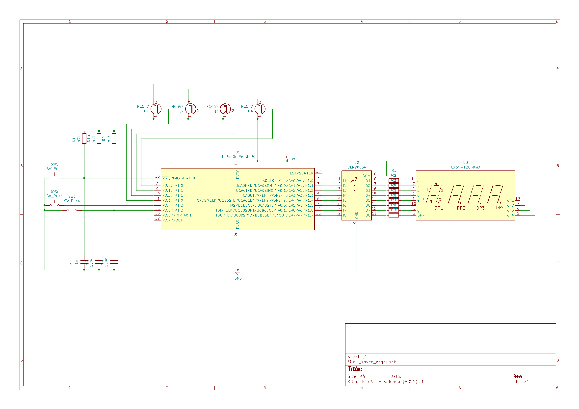
    I want to introduce a watch - working on MSP430G2553.

    Electrical schematics:

    #include <msp430.h>
    
    #define a 0x01           //00 0000 0000 0001 segment A
    #define b 0x02           //00 0000 0000 0010 segment B
    #define c 0x04           //00 0000 0000 0100 segment C
    #define d 0x08           //00 0000 0000 1000 segment D
    #define e 0x10           //00 0000 0001 0000 segment E
    #define f 0x20           //00 0000 0010 0000 segment F
    #define g 0x40           //00 0000 0100 0000 segment G
    #define DP     0x80      //00 0000 1000 0000 segment H - Dot Point
    
    #define Dig_1  0x01   //P2.0 Common Anode
    #define Dig_2  0x02   //P2.1 Common Anode
    #define Dig_3  0x04   //P2.2 Common Anode
    #define Dig_4  0x08   //P2.3 Common Anode
    
    #define S1     0x10   //P2.4 Button 1
    #define S2     0x20   //P2.5 Button 2
    
    int display_min[]={a+b+c+d+e+f, b+c, a+b+d+e+g, a+b+c+d+g, b+c+f+g, a+c+d+f+g, a+c+d+e+f+g, a+b+c, a+b+c+d+e+f+g, a+b+c+d+f+g};
    int display_hour[]={a+b+c+d+e+f, b+c, a+b+d+e+g, a+b+c+d+g, b+c+f+g, a+c+d+f+g, a+c+d+e+f+g, a+b+c, a+b+c+d+e+f+g, a+b+c+d+f+g};
    
    //clock variables
    volatile unsigned int j;
    volatile unsigned int TI_second = 0;
    volatile unsigned int TI_minute = 0;
    volatile unsigned int TI_hour = 0;
    volatile unsigned int dig_num = 0;
    volatile unsigned int flag_dp = 0x01;
    volatile unsigned int k = 0;
    volatile unsigned int l = 0;
    
    void Get_time(void)
    {
        j++;
        if (j==10) flag_dp = 0;   // Clear DP after 0,5 second
        if (j==20)   //50mS * 20 = 1sec.
            {
                j=0;
                TI_second++;
                flag_dp = 1;   // Set DP for 0,5 second
            }
        if (TI_second==60)
            {
                TI_second = 0;
                TI_minute++;
            }
        if (TI_minute>=60)
            {
                TI_minute = 0;
                TI_hour++;
            }
        if (TI_hour>=24)
            {
                TI_hour = 0;
            }
    }
    
    
    void Display_time(void)
        {
          switch( dig_num )
          {
            case 0:
              {
                P1OUT = display_hour[TI_hour/10];    // First digit of hour set cathodes
                P1OUT &= ~DP;                        // Clear dot point here
                P2OUT |= BIT0;                       // First digit anode high
                P2OUT &= ~0x0E;                      // Other digit anodes low
                dig_num = 1;                         // goto next digit
              }
              break;
    
           case 1:
             {
                P1OUT = display_hour[TI_hour%10];    // Second digit of hour set cathodes
                P2OUT |= BIT1;                       // Second digit anode high
                P2OUT &= ~0x0D;                      // Other digit anodes low
                    if(flag_dp == 1)                 // Every one second
                        {
                            P1OUT ^= DP;             // Set DP cathode
                        }
                dig_num = 2;                         // goto next digit
             }
             break;
    
          case 2:
            {
                P1OUT = display_min[TI_minute/10];   // First digit of minute set cathodes
                P1OUT &= ~DP;                        // Clear dot point here
                P2OUT |= BIT2;                       // Third digit anode high
                P2OUT &= ~0x0B;                      // Other digit anodes low
                dig_num = 3;                         // goto next digit
            }
            break;
    
          case 3:
            {
                P1OUT = display_min[TI_minute%10];    // Second digit of minute set cathodes
                P1OUT &= ~DP;                         // Clear dot point here
                P2OUT |= BIT3;                        // Fourth digit anode high
                P2OUT &= ~0x07;                       // Other digit anodes low
                dig_num = 0;                          // goto next digit (first)
            }
            break;
          }
        }
    
    void Change_time(void)
    {
    if(!(P2IN&S1))       // If button S1 is pressed
        {
            k++;             // Increment k value
            if(k==2)         // Button S1 still pressed after 2 intervals
            {
            TI_hour++;   // Increment one hour
            Get_time();  // Update hour
            }
        }
    if((P2IN&S1)) k=0;   // If button S1 is released
    
    if(!(P2IN&S2))       // If button S1 is pressed
        {
            l++;             // Increment k value
            if(l==2)         // Button S1 still pressed after 2 intervals
            {
            TI_minute++; // Increment one hour
            Get_time();  // Update hour
            }
        }
        if((P2IN&S2)) l=0;   // If button S2 is released
        }
    
    int main(void)
    {
          //initialization
          WDTCTL = WDTPW + WDTHOLD;     // Stop watchdog timer
          BCSCTL1 = CALBC1_1MHZ;        // Set MCLK 1MHz
          DCOCTL = CALDCO_1MHZ;
          BCSCTL2 = SELM_0 | DIVM_0 | DIVS0; // Set SMCLK 1MHz
    
          //----Ports settings----------------------------------------------------------
          P1OUT = 0xFF;        // Set Port 1 pin HIGH
          P2OUT = 0xFF;        // Set Port 2 pin HIGH
          P1DIR = 0xFF;        // Set Port 1 as output
          P2DIR = 0x0F;        // Set Port 2 0-3 pins as output
          P2REN |= (S1+S2);    // Set resistor to VCC at S1 and S2
    
          //----TimerA settings---------------------------------------------------------
          TA0CCTL1 |= CCIE;                  // CCR0 interrupt enabled
          TA0CCTL2 |= CCIE;                  // CCR1 interrupt enabled
          TA0CTL = TASSEL_2 + MC_2 + TAIE;   // Source SMCLK, Continous Mode, Interrupt enabled
          TA0CCR0 = 50000;                   // not using but set
          TA0CCR1 =  25000;                  // 25000 in cont mode is 50 ms
          TA0CCR2 =  2500;                   // 2500  in cont mode is 5 ms
    
        //---Interrupts settings--------------------------------------------------------
          _EINT();                           // __enable_interrupts
    
        //---Variables settings---------------------------------------------------------
          dig_num = 0;                       // start from first digit
    
          while(1)      // infinity loop, timer will interrupt all
          {}
    }
    
    // Timer 0 A1 interrupt service routine
    #pragma vector = TIMER0_A1_VECTOR
    __interrupt void TIMER0_A1_ISR( void )
    {
    switch( TAIV )
        {
            case  2:     // CCR1
                {
                    Get_time();          // update time
                    TA0CCR1 += 25000;    // Add Offset to CCR1 50ms
                    Change_time();       // function to set new time
                }
                break;
    
            case  4:    // CCR2
                {
                    Display_time();   // refresh screen
                    TA0CCR2 += 2500;  // Add offset 5ms ~50Hz
    
                }
                break;
    
            case 10:
            break;
          }
    }

    Now I will create temperature sensor with display, using seven segment LED Disp.

    But I will not be editing this project.
    Because - it works for 3 days and still showing good hour with battery.

    I have other ideas and other uC. ;)

    Thanks Chris,

    Problem resolved!

**Attention** This is a public forum