This thread has been locked.

If you have a related question, please click the "Ask a related question" button in the top right corner. The newly created question will be automatically linked to this question.

RTOS/MSP432P401R: Missing Characters on 1.5MBaud UART Operation

Part Number: MSP432P401R

Tool/software: TI-RTOS

Hi, we have been working on MSP432P401R Launchpads using EUSCI A0/A2 as 1.5MBaud UART and found out that some characters are missing in every string of characters transmission. And the characters are sent in running sequence. We have checked that transmitted data using logic analyzer, they are all correct. So the problem lies with the UART receive.

The set up works perfectly fine for other baudrates such as 115200, 460800, 921600.

To segregate the problem from our main application code which is running on multiple threads on two UARTs, We have reduced it to single threaded application running on 1 UART, the problem still persists.

We have attempted the following methods but the operation on 1.5MBaud still fails:

1) Changed DCO clock frequency from 12MHz to 48MHz;

2) Changed from DCO to use HFXTCLK External clock;

3) Changed driver RingBuffer byte size from 32 to 320 or even to a larger size of 1024;

4) UART_read is configured as blocking mode or callback mode.

5) I also tried the UART_readPolling to see if it's interrupt issue, there are still missing characters.

6) Use of a shorter sequence string such as 30 bytes instead of 320 bytes, there are still missing characters.

Finally we use UART driver to check for errors in the hwi (UARTMSP432_hwiIntFxn), and for those problematic sequence with missing characters, the hardware interrupt returns an overrun error. It seems that the MSP432 isn’t fast enough to receive back-to-back characters at 1.5MBaud.

Kindly revert to us any pointers to solve the 1.5MBaud issue as this is very urgent. Thanks.

  • What is the USCI clock frequency?
  • I tried 12M, 24M and 48Mhz EUSCI clock, all generated from DCO 48Mhz.

  • You can't use 48MHz. The max for the eUSCI is 24.

  • Have you tried to use the DMA to move the data?

    Regards,
    Chris
  • Hello Lok,

    Does the suggestion from Chris help?

    Regards,
    Sai
  • Hi,

    We have yet to attempt DMA method to move UART data. Do you have any sample codes that we can use for TI-RTOS to perform DMA transfer for UART data?

    Actually we have found out that the missing characters is caused by short interval burst of UART data being sent. If we increase the interval between the bytes transmission, the UART reception works fine. However, we have a timing requirement to meet, thus we still need to send relatively short interval burst.

    We have tried to use "no RTOS" TI driver to perform the reception, it works well for short burst transmission. So our conclusion is that TI-RTOS has some constraint in timing when come to UART receive. But we needed TI-RTOS to run our multi-tasking applications.

    Any other suggestions apart from DMA method are welcomed!

  • Heya, I've just finished writing a UARTMSP432DMA.c/h version for use with the bluetooth stack... I'll share my code and may it help you implement the DMA functions.. it took two weeks to modify the re-implement this including a modification to the HwiP library to trickly up Yeild required, so feel free to remove that function.

    The code uses a TIMER_32 as a "Rx IDLE" indicator which isn't present in the MSP432. I also use an extra DMA channel to re-activate this on every byte reception using a scatter gather task list, which auto refreshes itself by copying back the control member of the DMA structure, that way it continues to loop indefinitely without interaction from code.

    I've removed the callback method for both write and read, I don't find these useful to be honest. A blocking write which returns once data is written into the send queue is better IMHO, also a readAsync call that passes back to the caller a continious buffer and length which is from the DMA pign pong buffer prevents double copying by the reciever, or worst yet, tripple buffering by intterupt -> ring -> memcpy to userspace.

    The text modes have also been stripped for efficiency, I just dont use the UART for that purpose, that's another layer on top. If you want to have very quick handling of incoming bytes with a defined header, in text mode, co-opt a timer_a peripheral and use a capture compare register as your check for header or footer.. insert the copy from RX buffer into compare registers and sue those as "if like" statements.. winning :) I think there is #define out code which has a double buffering of the rx data incase you want to inspect it before/as it goes into the ping pong rx buffer.

    Attached is the export of my driver lib project and my main c.h file with the hwAttrs structures. Cherry pick out the UART DMA feature. Do note that I have lingering direct TIMER_32 references in the uart driver (not from config) and RTS ping toggling, you may not have those so remove as required.

    I have not debugged the UARTMSP432DMA_read() function as i'm using the readAsync exclusively. It should work as the async one, only with a memory copy back to the original buffer.

    Getting the DMA ping pong with idle timeout working without error takes a bit of effort... I hope this helps. Purhaps something like this could make its way into the driverlib SDK or the driverlib source, with history put into github so we (and others) can fork and demonstrate modifications that are useful.

    This code was writen on a MSP432P4011, most of the #define statements should work between the MSP432P401R and the later revision of chip. My mods also include the corrected #define for TIMER3 and EUSCI_B2 (or wahtever it is ) excluded from driverlib builds. It doesn't build otherwise, but I guess it should just build for the largest chip as those functions will never be called from other peoples code?... meh.. only a few mods. The code has been merged with "simplelink_msp432p4_sdk_2_40_00_10" so most of it should be up to date, albeit with my mods.

    Example usage;

    /*
     *  =============================== Timer ===============================
     */
    #include <ti/drivers/Timer.h>
    #include <ti/drivers/timer/TimerMSP432.h>
    
    static TimerMSP432_Object timerMSP432Objects[MSP432P401X_TIMERCOUNT];
    
    const TimerMSP432_HWAttrs timerMSP432HWAttrs[MSP432P401X_TIMERCOUNT] = {
        /* Timer32_0 */
        {
            .timerBaseAddress = TIMER32_0_BASE,
            .clockSource = TIMER_A_CLOCKSOURCE_SMCLK,
            .intNum = INT_T32_INT1,
            .intPriority = NVIC_PRIO(CAPTURE_PRIO)
        },
        /* Timer32_1 */
        {
            .timerBaseAddress = TIMER32_1_BASE,
            .clockSource = TIMER_A_CLOCKSOURCE_SMCLK,
            .intNum = INT_T32_INT2,
            .intPriority = NVIC_PRIO(CAPTURE_PRIO)
        }
    };
    
    const Timer_Config Timer_config[MSP432P401X_TIMERCOUNT] = {
        {
            .fxnTablePtr = &TimerMSP432_Timer32_fxnTable,
            .object = &timerMSP432Objects[MSP432P401X_TIMER_T32_0],
            .hwAttrs = &timerMSP432HWAttrs[MSP432P401X_TIMER_T32_0]
        },
        {
            .fxnTablePtr = &TimerMSP432_Timer32_fxnTable,
            .object = &timerMSP432Objects[MSP432P401X_TIMER_T32_1],
            .hwAttrs = &timerMSP432HWAttrs[MSP432P401X_TIMER_T32_1]
        }
    };
    
    const uint_least8_t Timer_count = MSP432P401X_TIMERCOUNT;
    
    /*
     *  =============================== UART ===============================
     */
    #include <ti/drivers/UART.h>
    #include <ti/drivers/uart/UARTMSP432DMA.h>
    
    static UARTMSP432DMA_Object uartMSP432Objects[MSP432P401X_UARTCOUNT];
    #if defined(__TI_COMPILER_VERSION__)
    #pragma DATA_ALIGN(uartMSP432RingBuffer, 128)
    #endif
    static unsigned char uartMSP432RingBuffer[MSP432P401X_UARTCOUNT][1024];
    #if defined(__TI_COMPILER_VERSION__)
    #pragma DATA_ALIGN(uartMSP432WriteBuffer, 128)
    #endif
    static unsigned char uartMSP432WriteBuffer[MSP432P401X_UARTCOUNT][1024];
    
    
    /*
     * The baudrate dividers were determined by using the MSP432 baudrate
     * calculator
     * software-dl.ti.com/.../index.html
     */
    const UARTMSP432DMA_BaudrateConfig uartMSP432Baudrates[] = {
        /* {baudrate, input clock, prescalar, UCBRFx, UCBRSx, oversampling} */
        {921600, 24e6,   1, 10,   0, 1},
        {921600, 16e6,  17,  0,  74, 0},
        {921600,  6e6,   6,  0, 170, 0},
        {460800, 24e6,   3,  4,   2, 1},
        {460800, 16e6,   2,  2, 187, 1},
        {460800,  6e6,  13,  0,   0, 0},
        {230400, 24e6,   6,  8,  32, 1},
        {230400, 16e6,   4,  5,  85, 1},
        {230400,  6e6,   1, 10,   0, 1},
        {115200, 24e6,   13, 0,  37, 1},
        {115200, 16e6,   8, 10, 247, 1},
        {115200, 12e6,   6,  8,  32, 1},
        {115200, 06e6,   3,  4,   2, 1},
        {115200, 03e6,   1, 10,   0, 1},
        {9600,   24e6, 156,  4,   0, 1},
        {9600,   16e6, 104,  2, 182, 1},
        {9600,   12e6,  78,  2,   0, 1},
        {9600,   06e6,  39,  1,   0, 1},
        {9600,   03e6,  19,  8,  85, 1},
        {9600,  32768,   3,  0, 146, 0}
    };
    
    extern long hal_uart_error(UART_Handle handle,  uint32_t error);
    extern void BspSwitchUartError(UART_Handle handle,  uint32_t error);
    
    const UARTMSP432DMA_HWAttrsV1 uartMSP432HWAttrs[MSP432P401X_UARTCOUNT] = {
        {
            .baseAddr = EUSCI_A2_BASE,
            .intNum = INT_EUSCIA2,
            .clockSource = EUSCI_A_UART_CLOCKSOURCE_SMCLK,
            .bitOrder = EUSCI_A_UART_LSB_FIRST,
            .numBaudrateEntries = sizeof(uartMSP432Baudrates) /
                sizeof(UARTMSP432DMA_BaudrateConfig),
            .baudrateLUT = uartMSP432Baudrates,
            .ringBufPtr  = uartMSP432RingBuffer[MSP432P401X_UART_BT],
            .writeBufPtr = uartMSP432WriteBuffer[MSP432P401X_UART_BT],
            .ringBufSize = sizeof(uartMSP432RingBuffer[MSP432P401X_UART_BT]),
            .writeBufSize = sizeof(uartMSP432WriteBuffer[MSP432P401X_UART_BT]),
            .rxPin = UARTMSP432DMA_P2_1_UCA2RXD,
            .txPin = UARTMSP432DMA_P2_0_UCA2TXD,
            .rtsPinBitBand = (volatile uint16_t *)BITBAND_PERI_ADR(P3->OUT, 6), // P3.6 direct output
            .errorFxn = hal_uart_error,
            .timeoutTmrIdx = MSP432P401X_TIMER_T32_1,
            .dmaIntNum = DMA_INT0,
            .bfrDMAChannelIndex = DMA_CH3_RESERVED0,
            .rxDMAChannelIndex = DMA_CH5_EUSCIA2RX,
            .txDMAChannelIndex = DMA_CH4_EUSCIA2TX,
            .minDmaTransferSize = 10,
            .intPriority = NVIC_PRIO(DMA_PRIO)
        }
    };
    
    const UART_Config UART_config[MSP432P401X_UARTCOUNT] = {
        {   // Bluetooth UART
            .fxnTablePtr = &UARTMSP432DMA_fxnTable,
            .object = &uartMSP432Objects[MSP432P401X_UART_BT],
            .hwAttrs = &uartMSP432HWAttrs[MSP432P401X_UART_BT]
        }
    };

    Segger SysView calls can be stripped out too.. 

    Requirements;

    3x DMA Channels, RX, TX of eUSCI peripheral + Spare DMA channel for Ping Pong buffer, activated by "software trigger" from real RX channel. The space channel can be any un-used DMA channel selected by DMA_CHX_RESERVED0 in the hwAttrs structure.

    1x TIMER_32 resource

    msp432_driverlib_uartdma.zip

    There just aren't enough CPU cycles to pull from the uart at > 1MB

  • So that google searches finds this, below is a snipper from the example i've posted which shows a scatter gatherer DMA channel used to initialise a one-shot periodic TIMER_32 and re-arm the transfer plus trigger a ping pong DMA buffer to enable high speed reads through a driverlib function.

    It is very important to note that the call to MAP_DMA_setChannelScatterGather sets the "isPeriphSG" parameter to TRUE, and that the LAST scatter task is set to "UDMA_MODE_PER_SCATTER_GATHER". This ensures that the tasks execute when an RX byte is recieved, and that the task list is rearmed only once another byte is received.

    The last scatter command copies a buffered DMA_ControlTable->control uint32_t back to the primary DMA table, which makes the whole task list iterate indefinitely. Ya :)

    Scatter Gatherer DMA setup:

     {
    #if 0
            /* Clear the RX buffer for the first read*/
            DMA_ControlTable BufferClearRX =
                    DMA_TaskStructEntry(1, UDMA_SIZE_8,
                        UDMA_SRC_INC_NONE, &dummy_u8_rxBuf,
                        UDMA_DST_INC_NONE, &object->rx_dmaRxBuffer,
                        UDMA_ARB_4, (UDMA_MODE_MEM_SCATTER_GATHER));
            /* Perform the actual read operatiopn */
            DMA_ControlTable BufferRX =
                    DMA_TaskStructEntry(1, UDMA_SIZE_8,
                        UDMA_SRC_INC_NONE, (void *) MAP_UART_getReceiveBufferAddressForDMA(hwAttrs->baseAddr),
                        UDMA_DST_INC_NONE, &object->rx_dmaRxBuffer,
                        UDMA_ARB_4, (UDMA_MODE_MEM_SCATTER_GATHER));
    #endif
            /* Trigger ping-pong buffer */
            DMA_ControlTable TriggerPingPong =
                    DMA_TaskStructEntry(1, UDMA_SIZE_32,
                       UDMA_SRC_INC_NONE, &object->rx_dmaSwReq,
                       UDMA_DST_INC_NONE, &DMA_Control->SWREQ,
                       UDMA_ARB_4, (UDMA_MODE_MEM_SCATTER_GATHER));
            /* Setup idle timeout as 2x Rx rate */
            DMA_ControlTable IdleTimeout =
                    DMA_TaskStructEntry(1, UDMA_SIZE_32,
                       UDMA_SRC_INC_NONE, &object->rx_dmaIdleTimeout,
                       UDMA_DST_INC_NONE, &TIMER32_2->LOAD,
                       UDMA_ARB_4, (UDMA_MODE_MEM_SCATTER_GATHER));
            /* Reset task control size */
            DMA_ControlTable resetTask =
                    DMA_TaskStructEntry(1, UDMA_SIZE_32,
                       UDMA_SRC_INC_NONE, &object->rx_dmaTaskControl,
                       UDMA_DST_INC_NONE, object->rx_dmaTaskCtrl,
                       UDMA_ARB_4, (UDMA_MODE_PER_SCATTER_GATHER));
    
            //dma_dblBufferTimerIdle[eTask0ClearDoubleBuffer] = BufferClearRX;
            /* Task 1: Read the RX buffer */
            //dma_dblBufferTimerIdle[eTask1DoubleBufferRX] = BufferRX;
            /* Task 2: Reload the idle timeout */
            dma_dblBufferTimerIdle[eTask2ReloadIdleTimeout] = IdleTimeout;
            /* Task 4: Trigger ping-pong buffer */
            dma_dblBufferTimerIdle[eTask4TriggerPingPongDMA] = TriggerPingPong;
            /* Task 5: Reset the task control count */
            dma_dblBufferTimerIdle[eTask5ResetTaskCount] = resetTask;
        }
    
        /* Setup scatter gatherer channels here */
        MAP_DMA_setChannelScatterGather(hwAttrs->rxDMAChannelIndex, eTaskMax, (void*)dma_dblBufferTimerIdle, 1);
        /* Buffer the task control list value so the task list loops forever */
        object->rx_dmaTaskControl = *object->rx_dmaTaskCtrl; /*(UDMA_CHCTL_DSTINC_32
                | UDMA_CHCTL_DSTSIZE_32 | UDMA_CHCTL_SRCINC_32
                | UDMA_CHCTL_SRCSIZE_32 | UDMA_CHCTL_ARBSIZE_4
                | (((eTaskMax * 4) - 1) << UDMA_CHCTL_XFERSIZE_S)
                | UDMA_CHCTL_XFERMODE_MEM_SG);*/
        MAP_DMA_assignChannel(hwAttrs->rxDMAChannelIndex);
        MAP_DMA_clearInterruptFlag(hwAttrs->rxDMAChannelIndex & 0x0F);
        MAP_DMA_enableChannel(hwAttrs->rxDMAChannelIndex);
    
        MAP_DMA_clearInterruptFlag(hwAttrs->bfrDMAChannelIndex & 0x0F);
        MAP_DMA_enableInterrupt(hwAttrs->dmaIntNum);
    
        MAP_Interrupt_enableInterrupt(hwAttrs->dmaIntNum);


    eUSCI Scatter Gatherer task list:

    static uint8_t dummy_u8_rxBuf = 0xF1;
    static uint32_t dummy_u32_rxControl;
    static uint32_t dummy_u32_swTrig = (1<<UART_DBL_BUF_CH);
    static uint32_t dummy_u32_idleTime = (24e6/(115200/10)) * 8;
    /* Prescale divide by 4, so set idleTime divide by 2 so the timeout is 2x rx time */
    static uint32_t dummy_u32_idleControl =
            TIMER32_CONTROL_ONESHOT | TIMER32_CONTROL_IE |
            TIMER32_CONTROL_ENABLE | TIMER32_CONTROL_MODE ;
    static uint8_t  dummy_u8_rxBuffer;
    
    typedef enum uartIdleTimeoutSequence {
    #if 0
        eTask0ClearDoubleBuffer = 0,
        eTask1DoubleBufferRX,
    #endif
        eTask2ReloadIdleTimeout = 0,
        eTask3RearmIdleTimer,
        eTask4TriggerPingPongDMA,
        eTask5ResetTaskCount,
        eTaskMax
    } uartIdleTimeoutSequence;
    
    /*
     * DMA Channel Uart RX
     *
     */
    static DMA_ControlTable dma_dblBufferTimerIdle[eTaskMax] =
    {
        /* Task 0: Clear the RXBuffer and wait for the peripheral trigger */
    #if 0
        DMA_TaskStructEntry(1, UDMA_SIZE_8,
            UDMA_SRC_INC_NONE, &dummy_u8_rxBuf /* Read the RX buffer */,
            UDMA_DST_INC_NONE, &dummy_u8_rxBuffer,
            UDMA_ARB_4, (UDMA_MODE_PER_SCATTER_GATHER)),
        /* Task 1: Read the RX buffer to the double buffer point */
        DMA_TaskStructEntry(1, UDMA_SIZE_8,
            UDMA_SRC_INC_NONE, &EUSCI_A2->RXBUF /* Read the RX buffer */,
            UDMA_DST_INC_NONE, &dummy_u8_rxBuffer,
            UDMA_ARB_4, (UDMA_MODE_MEM_SCATTER_GATHER)),
    #endif
        /* Task 2: Reload the idle timeout */
        DMA_TaskStructEntry(1, UDMA_SIZE_32,
            UDMA_SRC_INC_NONE, &dummy_u32_idleTime /* Setup idle timeout as 2x Rx rate */,
            UDMA_DST_INC_NONE, &TIMER32_2->LOAD,
            UDMA_ARB_4, (UDMA_MODE_MEM_SCATTER_GATHER)),
        /* Task 3: Re-arm the idle timeout timer */
        DMA_TaskStructEntry(1, UDMA_SIZE_32,
            UDMA_SRC_INC_NONE, &dummy_u32_idleControl /* Re-arm the idle timeout */,
            UDMA_DST_INC_NONE, &TIMER32_2->CONTROL,
            UDMA_ARB_4, (UDMA_MODE_MEM_SCATTER_GATHER)),
        /* Task 4: Trigger the ping-pong task */
        DMA_TaskStructEntry(1, UDMA_SIZE_32,
            UDMA_SRC_INC_NONE, &dummy_u32_swTrig /* Trigger ping-pong buffer */,
            UDMA_DST_INC_NONE, &DMA_Control->SWREQ,
            UDMA_ARB_4, (UDMA_MODE_MEM_SCATTER_GATHER)),
        /* Task 5: Reset the task control count */
        DMA_TaskStructEntry(1, UDMA_SIZE_32,
           UDMA_SRC_INC_NONE, &dummy_u32_rxControl /* Trigger ping-pong buffer */,
           UDMA_DST_INC_NONE, &dummy_u32_rxControl,
           UDMA_ARB_4, (UDMA_MODE_PER_SCATTER_GATHER))
    };
  • Hi Lucas, thanks a lot for the detailed description on how to include DMA functions into UART.

    I tried to follow the steps you mentioned, these are what I have done:

    1) Installed simplelink_msp432p4_sdk_2_40_00_10.

    2) Copied UARTMSP432DMA.c and UARTMSP432DMA.h from msp432_driverlib_uartdma.zip into C:\ti\simplelink_msp432p4_sdk_2_40_00_10\source\ti\drivers\uart\ and renamed them to UARTMSP432.c and UARTMSP432.h respectively.

    3) Successfully compiled the SimpleLink drivers.

    4) Modified MSP_EXP432P401R.c in my main program accordingly to the example usage you posted.

    5) Successfully compiled my main program.

    So finally I ran the program, it hanged at the UART_init(). Upon checking, UART_init() calls additional function UDMAMSP432_init() which comes from dma driver files. I tried to compare "C:\ti\simplelink_msp432p4_sdk_2_40_00_10\source\ti\drivers\" and "msp432_driverlib_uartdma\msp432_driverlib\drivers" and discovered many driver files are different. Did you modify all those files? Or could it be DMA is not configured properly?

    Let me know if you have any suggestions. Thanks!

  • Yes i've been quite busy in terms of modifications to the driverlib package. The major change is the return code from all Hwi hooked interrupts calls. You could ignore that and revert it to just a simple void return type and alot of the changes go away..

    I'm actively refining the receive functions at the moment, had a few ideas to divide the receive ring buffer into discrete blocks (~128-256 bytes) within a 1-2kb buffer so I can enact two flow control points. <= one block free results in RTS assertion, hopefly steming the flow of bytes into the RxBuffer. Then once the actual buffer reaches full, masking the DMA scatter gather channel entirely to prevent an overflow over the tail of the ring buffer.

    Also implemented the _Read() function as per the original prototype (without the min shenanagins) and made the iterations waiting for more data easy to follow.

    I also had a few hang over, from many iterations, bugs around enabling the timer in the Read routine so that the timeout function does not continually callback through semaphore posts when more data is clearly wanted, and a true timeout (rx idle) has not yet been reached.

    The concept of ReadAsync is still the same, the actual dma buffer gets passed back to the caller for inspection.

    Alot more code commenting going in this week. I'll post back the c/h files in a few hours. if you have skype you can msg me .. my.name at riotinto dot com

  • I see, thanks for the effort! I suppose you have tested the DMA functionality on UART, does it work well on high baudrate such 1.5MBaud?
  • I was just about to get to that step, I've got it running at a lower speed on my bluetooth solution right now. I am planning on pumping the board rate right up above 1mbit, whole race to idle.

    I have a 401R here with me and a 4111 on my desk at home. will post later tonight. will try faster
  • Hi Lucas, any update for baudrate above 1Mbit?

  • I have changed the return code from Hwi hooked interrupts calls and revert to simple void return type for most of the drivers.

    The drivers are compiled successfully. I also followed the TIMER_32 config and UART config tightly as mentioned in your usage.

    However, the program just won't run passed simple UART_init(). It always hanged there. There is no way for me to dig into driver to debug, or there is a way to debug? The other reason could also be some configurations are not set properly.

    Can you help me inspect whether my MSP_EXP432P401R.c/.h are correct? Thanks a lot!

    1727.MSP_EXP432P401R.c
    /*
     * Copyright (c) 2015-2018, Texas Instruments Incorporated
     * All rights reserved.
     *
     * Redistribution and use in source and binary forms, with or without
     * modification, are permitted provided that the following conditions
     * are met:
     *
     * *  Redistributions of source code must retain the above copyright
     *    notice, this list of conditions and the following disclaimer.
     *
     * *  Redistributions in binary form must reproduce the above copyright
     *    notice, this list of conditions and the following disclaimer in the
     *    documentation and/or other materials provided with the distribution.
     *
     * *  Neither the name of Texas Instruments Incorporated nor the names of
     *    its contributors may be used to endorse or promote products derived
     *    from this software without specific prior written permission.
     *
     * THIS SOFTWARE IS PROVIDED BY THE COPYRIGHT HOLDERS AND CONTRIBUTORS "AS IS"
     * AND ANY EXPRESS OR IMPLIED WARRANTIES, INCLUDING, BUT NOT LIMITED TO,
     * THE IMPLIED WARRANTIES OF MERCHANTABILITY AND FITNESS FOR A PARTICULAR
     * PURPOSE ARE DISCLAIMED. IN NO EVENT SHALL THE COPYRIGHT OWNER OR
     * CONTRIBUTORS BE LIABLE FOR ANY DIRECT, INDIRECT, INCIDENTAL, SPECIAL,
     * EXEMPLARY, OR CONSEQUENTIAL DAMAGES (INCLUDING, BUT NOT LIMITED TO,
     * PROCUREMENT OF SUBSTITUTE GOODS OR SERVICES; LOSS OF USE, DATA, OR PROFITS;
     * OR BUSINESS INTERRUPTION) HOWEVER CAUSED AND ON ANY THEORY OF LIABILITY,
     * WHETHER IN CONTRACT, STRICT LIABILITY, OR TORT (INCLUDING NEGLIGENCE OR
     * OTHERWISE) ARISING IN ANY WAY OUT OF THE USE OF THIS SOFTWARE,
     * EVEN IF ADVISED OF THE POSSIBILITY OF SUCH DAMAGE.
     */
    
    /*
     *  ======== MSP_EXP432P401R.c ========
     *  This file is responsible for setting up the board specific items for the
     *  MSP_EXP432P401R board.
     */
    
    #include <stdbool.h>
    #include <stddef.h>
    #include <stdint.h>
    
    #ifndef DeviceFamily_MSP432P401x
    #define DeviceFamily_MSP432P401x
    #endif
    
    #include <ti/devices/DeviceFamily.h>
    
    #include <ti/drivers/Power.h>
    #include <ti/drivers/power/PowerMSP432.h>
    
    #include <ti/devices/msp432p4xx/inc/msp.h>
    #include <ti/devices/msp432p4xx/driverlib/rom.h>
    #include <ti/devices/msp432p4xx/driverlib/rom_map.h>
    #include <ti/devices/msp432p4xx/driverlib/adc14.h>
    #include <ti/devices/msp432p4xx/driverlib/dma.h>
    #include <ti/devices/msp432p4xx/driverlib/gpio.h>
    #include <ti/devices/msp432p4xx/driverlib/i2c.h>
    #include <ti/devices/msp432p4xx/driverlib/interrupt.h>
    #include <ti/devices/msp432p4xx/driverlib/pmap.h>
    #include <ti/devices/msp432p4xx/driverlib/ref_a.h>
    #include <ti/devices/msp432p4xx/driverlib/spi.h>
    #include <ti/devices/msp432p4xx/driverlib/timer_a.h>
    #include <ti/devices/msp432p4xx/driverlib/timer32.h>
    #include <ti/devices/msp432p4xx/driverlib/uart.h>
    #include <ti/devices/msp432p4xx/driverlib/wdt_a.h>
    
    #include "MSP_EXP432P401R.h"
    
    /*
     *  =============================== ADC ===============================
     */
    #include <ti/drivers/ADC.h>
    #include <ti/drivers/adc/ADCMSP432.h>
    
    /* ADC objects */
    ADCMSP432_Object adcMSP432Objects[MSP_EXP432P401R_ADCCOUNT];
    
    /* ADC configuration structure */
    const ADCMSP432_HWAttrsV1 adcMSP432HWAttrs[MSP_EXP432P401R_ADCCOUNT] = {
        {
            .adcPin = ADCMSP432_P5_5_A0,
            .refVoltage = ADCMSP432_REF_VOLTAGE_INT_2_5V,
            .resolution = ADC_14BIT
        },
        {
            .adcPin = ADCMSP432_P5_4_A1,
            .refVoltage = ADCMSP432_REF_VOLTAGE_INT_1_45V,
            .resolution = ADC_8BIT
        }
    };
    
    const ADC_Config ADC_config[MSP_EXP432P401R_ADCCOUNT] = {
        {
            .fxnTablePtr = &ADCMSP432_fxnTable,
            .object = &adcMSP432Objects[MSP_EXP432P401R_ADC0],
            .hwAttrs = &adcMSP432HWAttrs[MSP_EXP432P401R_ADC0]
        },
        {
            .fxnTablePtr = &ADCMSP432_fxnTable,
            .object = &adcMSP432Objects[MSP_EXP432P401R_ADC1],
            .hwAttrs = &adcMSP432HWAttrs[MSP_EXP432P401R_ADC1]
        }
    };
    
    const uint_least8_t ADC_count = MSP_EXP432P401R_ADCCOUNT;
    
    /*
     *  =============================== ADCBuf ===============================
     */
    #include <ti/drivers/ADCBuf.h>
    #include <ti/drivers/adcbuf/ADCBufMSP432.h>
    
    /* ADC objects */
    ADCBufMSP432_Object adcbufMSP432Objects[MSP_EXP432P401R_ADCBUFCOUNT];
    
    ADCBufMSP432_Channels adcBuf0MSP432Channels[MSP_EXP432P401R_ADCBUF0CHANNELCOUNT] = {
        {
            .adcPin = ADCBufMSP432_P5_5_A0,
            .refSource = ADCBufMSP432_VREFPOS_AVCC_VREFNEG_VSS,
            .refVoltage = 3300000,
            .adcInputMode = ADCBufMSP432_SINGLE_ENDED,
            .adcDifferentialPin = ADCBufMSP432_PIN_NONE,
            .adcInternalSource = ADCBufMSP432_INTERNAL_SOURCE_MODE_OFF
        },
        {
            .adcPin = ADCBufMSP432_P5_4_A1,
            .refSource = ADCBufMSP432_VREFPOS_INTBUF_VREFNEG_VSS,
            .refVoltage = 2500000,
            .adcInputMode = ADCBufMSP432_SINGLE_ENDED,
            .adcDifferentialPin = ADCBufMSP432_PIN_NONE,
            .adcInternalSource = ADCBufMSP432_INTERNAL_SOURCE_MODE_OFF
        },
        {
            .adcPin = ADCBufMSP432_P5_5_A0,
            .refSource = ADCBufMSP432_VREFPOS_INTBUF_VREFNEG_VSS,
            .refVoltage = 2500000,
            .adcInputMode = ADCBufMSP432_SINGLE_ENDED,
            .adcDifferentialPin = ADCBufMSP432_PIN_NONE,
            .adcInternalSource = ADCBufMSP432_TEMPERATURE_MODE
        },
        {
            .adcPin = ADCBufMSP432_P5_5_A0,
            .refSource = ADCBufMSP432_VREFPOS_AVCC_VREFNEG_VSS,
            .refVoltage = 3300000,
            .adcInputMode = ADCBufMSP432_DIFFERENTIAL,
            .adcDifferentialPin = ADCBufMSP432_P5_4_A1,
            .adcInternalSource = ADCBufMSP432_INTERNAL_SOURCE_MODE_OFF
        },
    };
    
    /* ADC configuration structure */
    const ADCBufMSP432_HWAttrs adcbufMSP432HWAttrs[MSP_EXP432P401R_ADCBUFCOUNT] = {
        {
            .intPriority =  ~0,
            .channelSetting = adcBuf0MSP432Channels,
            .adcTimerTriggerSource = ADCBufMSP432_TIMERA1_CAPTURECOMPARE2,
            .useDMA = 1,
            .dmaIntNum = DMA_INT0,
            .adcTriggerSource = ADCBufMSP432_TIMER_TRIGGER,
            .timerDutyCycle = 50,
            .clockSource = ADCBufMSP432_ADC_CLOCK
        }
    };
    
    const ADCBuf_Config ADCBuf_config[MSP_EXP432P401R_ADCBUFCOUNT] = {
        {
            .fxnTablePtr = &ADCBufMSP432_fxnTable,
            .object = &adcbufMSP432Objects[MSP_EXP432P401R_ADCBUF0],
            .hwAttrs = &adcbufMSP432HWAttrs[MSP_EXP432P401R_ADCBUF0]
        }
    };
    
    const uint_least8_t ADCBuf_count = MSP_EXP432P401R_ADCBUFCOUNT;
    
    /*
     *  ============================= Capture =============================
     */
    #include <ti/drivers/Capture.h>
    #include <ti/drivers/capture/CaptureMSP432.h>
    
    CaptureMSP432_Object captureMSP432Objects[MSP_EXP432P401R_CAPTURECOUNT];
    
    const CaptureMSP432_HWAttrs captureMSP432HWAttrs[MSP_EXP432P401R_CAPTURECOUNT] = {
        /* Timer_A1 */
        {
            .timerBaseAddress = TIMER_A1_BASE,
            .clockSource = TIMER_A_CLOCKSOURCE_ACLK,
            .clockDivider = TIMER_A_CLOCKSOURCE_DIVIDER_1,
            .capturePort = CaptureMSP432_P7_7_TA1,
            .intPriority = NVIC_PRIO(CAPTURE_PRIO)
        },
        /* Timer_A2 */
        {
            .timerBaseAddress = TIMER_A2_BASE,
            .clockSource = TIMER_A_CLOCKSOURCE_ACLK,
            .clockDivider = TIMER_A_CLOCKSOURCE_DIVIDER_1,
            .capturePort = CaptureMSP432_P6_7_TA2,
            .intPriority = NVIC_PRIO(CAPTURE_PRIO)
        },
        /* Timer_A3 */
        {
            .timerBaseAddress = TIMER_A3_BASE,
            .clockSource = TIMER_A_CLOCKSOURCE_ACLK,
            .clockDivider = TIMER_A_CLOCKSOURCE_DIVIDER_1,
            .capturePort = CaptureMSP432_P8_2_TA3,
            .intPriority = NVIC_PRIO(CAPTURE_PRIO)
        }
    };
    
    const Capture_Config Capture_config[MSP_EXP432P401R_CAPTURECOUNT] = {
        {
            .fxnTablePtr = &CaptureMSP432_captureFxnTable,
            .object = &captureMSP432Objects[MSP_EXP432P401R_CAPTURE_TA1],
            .hwAttrs = &captureMSP432HWAttrs[MSP_EXP432P401R_CAPTURE_TA1]
        },
        {
            .fxnTablePtr = &CaptureMSP432_captureFxnTable,
            .object = &captureMSP432Objects[MSP_EXP432P401R_CAPTURE_TA2],
            .hwAttrs = &captureMSP432HWAttrs[MSP_EXP432P401R_CAPTURE_TA2]
        },
        {
            .fxnTablePtr = &CaptureMSP432_captureFxnTable,
            .object = &captureMSP432Objects[MSP_EXP432P401R_CAPTURE_TA3],
            .hwAttrs = &captureMSP432HWAttrs[MSP_EXP432P401R_CAPTURE_TA3]
        }
    };
    
    const uint_least8_t Capture_count = MSP_EXP432P401R_CAPTURECOUNT;
    
    /*
     *  =============================== DMA ===============================
     */
    #include <ti/drivers/dma/UDMAMSP432.h>
    
    #if defined(__TI_COMPILER_VERSION__)
    #pragma DATA_ALIGN(dmaControlTable, 256)
    #elif defined(__IAR_SYSTEMS_ICC__)
    #pragma data_alignment=256
    #elif defined(__GNUC__)
    __attribute__ ((aligned (256)))
    #endif
    static DMA_ControlTable dmaControlTable[16];
    
    /*
     *  ======== dmaErrorHwi ========
     *  This is the handler for the uDMA error interrupt.
     */
    static void dmaErrorHwi(uintptr_t arg)
    {
        int status = MAP_DMA_getErrorStatus();
        MAP_DMA_clearErrorStatus();
    
        /* Suppress unused variable warning */
        (void)status;
    
        while (1);
    }
    
    UDMAMSP432_Object udmaMSP432Object;
    
    const UDMAMSP432_HWAttrs udmaMSP432HWAttrs = {
        .controlBaseAddr = (void *)dmaControlTable,
        .dmaErrorFxn = (UDMAMSP432_ErrorFxn)dmaErrorHwi,
        .intNum = INT_DMA_ERR,
        .intPriority = (~0)
    };
    
    const UDMAMSP432_Config UDMAMSP432_config = {
        .object = &udmaMSP432Object,
        .hwAttrs = &udmaMSP432HWAttrs
    };
    
    /*
     *  ======== MSP_EXP432P401R_initGeneral ========
     */
    void MSP_EXP432P401R_initGeneral(void)
    {
        Power_init();
    }
    
    /*
     *  =============================== GPIO ===============================
     */
    #include <ti/drivers/GPIO.h>
    #include <ti/drivers/gpio/GPIOMSP432.h>
    
    /*
     * Array of Pin configurations
     * NOTE: The order of the pin configurations must coincide with what was
     *       defined in MSP_EXP432P401R.h
     * NOTE: Pins not used for interrupts should be placed at the end of the
     *       array.  Callback entries can be omitted from callbacks array to
     *       reduce memory usage.
     */
    GPIO_PinConfig gpioPinConfigs[] = {
        /* Input pins */
        /*
         * NOTE: Specifying FALLING edge triggering for these buttons to ensure the
         * interrupts are signaled immediately.  See the description of the
         * PowerMSP432 driver's automatic pin parking feature for this rationale.
         */
        /* MSP_EXP432P401R_GPIO_S1 */
        GPIOMSP432_P1_1 | GPIO_CFG_IN_PU | GPIO_CFG_IN_INT_FALLING,
        /* MSP_EXP432P401R_GPIO_S2 */
        GPIOMSP432_P1_4 | GPIO_CFG_IN_PU | GPIO_CFG_IN_INT_FALLING,
        
        //added tanws
        /* MSP_EXP432P401R_GPIO_P4_1 */
         /* Output GPIO for RTS */
        //GPIOMSP432_P4_1 | GPIO_CFG_IN_PU | GPIO_CFG_IN_INT_FALLING,
        GPIOMSP432_P4_1 | GPIO_CFG_OUT_STD | GPIO_CFG_OUT_STR_HIGH | GPIO_CFG_OUT_HIGH,
        
        /* MSP_EXP432P401R_GPIO_P4_6 */
        /* Input GPIO for RTS */
        //GPIOMSP432_P4_6 | GPIO_CFG_OUT_STD | GPIO_CFG_OUT_STR_LOW | GPIO_CFG_OUT_LOW,
        GPIOMSP432_P4_6 | GPIO_CFG_IN_PU | GPIO_CFG_IN_INT_FALLING,
        
        //end tanws
    
        /* MSP_EXP432P401R_SPI_MASTER_READY */
        GPIOMSP432_P5_7 | GPIO_DO_NOT_CONFIG,
        /* MSP_EXP432P401R_SPI_SLAVE_READY */
        GPIOMSP432_P6_0 | GPIO_DO_NOT_CONFIG,
    
        /* Output pins */
        /* MSP_EXP432P401R_GPIO_LED1 */
        GPIOMSP432_P1_0 | GPIO_CFG_OUT_STD | GPIO_CFG_OUT_STR_LOW | GPIO_CFG_OUT_LOW,
        /* MSP_EXP432P401R_GPIO_LED_RED */
        GPIOMSP432_P2_0 | GPIO_CFG_OUT_STD | GPIO_CFG_OUT_STR_HIGH | GPIO_CFG_OUT_LOW,
        
        //added tanws
        /* MSP_EXP432P401R_GPIO_P4_1 */
        /* Output GPIO for RTS */
        /*GPIOMSP432_P4_1 | GPIO_CFG_OUT_STD | GPIO_CFG_OUT_STR_HIGH | GPIO_CFG_OUT_LOW,*/
        
        //tanws
    
        /*
         * MSP_EXP432P401R_GPIO_LED_GREEN & MSP_EXP432P401R_GPIO_LED_BLUE are used for
         * PWM examples.  Uncomment the following lines if you would like to control
         * the LEDs with the GPIO driver.
         */
        /* MSP_EXP432P401R_GPIO_LED_GREEN */
         GPIOMSP432_P2_1 | GPIO_CFG_OUT_STD | GPIO_CFG_OUT_STR_HIGH | GPIO_CFG_OUT_LOW, 
        /* MSP_EXP432P401R_GPIO_LED_BLUE */
         GPIOMSP432_P2_2 | GPIO_CFG_OUT_STD | GPIO_CFG_OUT_STR_HIGH | GPIO_CFG_OUT_LOW, 
        /* MSP_EXP432P401R_SPI_CS1 */
        GPIOMSP432_P5_4 | GPIO_CFG_OUT_STD | GPIO_CFG_OUT_STR_LOW | GPIO_CFG_OUT_HIGH,
        /* MSP_EXP432P401R_SPI_CS2 */
        GPIOMSP432_P5_5 | GPIO_CFG_OUT_STD | GPIO_CFG_OUT_STR_LOW | GPIO_CFG_OUT_HIGH,
    
        /* MSP_EXP432P401R_SDSPI_CS */
        //tanws
        /* GPIOMSP432_P4_6 | GPIO_CFG_OUT_STD | GPIO_CFG_OUT_STR_LOW | GPIO_CFG_OUT_HIGH,*/
        //
    
        /* Sharp Display - GPIO configurations will be done in the Display files */
        GPIOMSP432_P4_3 | GPIO_DO_NOT_CONFIG, /* SPI chip select */
        //tanws
        /* GPIOMSP432_P4_1 | GPIO_DO_NOT_CONFIG, */  /* LCD power control */
        //
        GPIOMSP432_P6_0 | GPIO_DO_NOT_CONFIG, /*LCD enable */
    };
    
    /*
     * Array of callback function pointers
     * NOTE: The order of the pin configurations must coincide with what was
     *       defined in MSP_EXP432P401R.h
     * NOTE: Pins not used for interrupts can be omitted from callbacks array to
     *       reduce memory usage (if placed at end of gpioPinConfigs array).
     */
    GPIO_CallbackFxn gpioCallbackFunctions[] = {
        /* MSP_EXP432P401R_GPIO_S1 */
        NULL,
        /* MSP_EXP432P401R_GPIO_S2 */
        NULL,
        /* MSP_EXP432P401R_SPI_MASTER_READY */
        NULL,
        /* MSP_EXP432P401R_SPI_SLAVE_READY */
        NULL
    };
    
    const GPIOMSP432_Config GPIOMSP432_config = {
        .pinConfigs = (GPIO_PinConfig *)gpioPinConfigs,
        .callbacks = (GPIO_CallbackFxn *)gpioCallbackFunctions,
        .numberOfPinConfigs = sizeof(gpioPinConfigs)/sizeof(GPIO_PinConfig),
        .numberOfCallbacks = sizeof(gpioCallbackFunctions)/sizeof(GPIO_CallbackFxn),
        .intPriority = (~0)
    };
    
    /*
     *  =============================== I2C ===============================
     */
    #include <ti/drivers/I2C.h>
    #include <ti/drivers/i2c/I2CMSP432.h>
    
    I2CMSP432_Object i2cMSP432Objects[MSP_EXP432P401R_I2CCOUNT];
    
    const I2CMSP432_HWAttrsV1 i2cMSP432HWAttrs[MSP_EXP432P401R_I2CCOUNT] = {
        {
            .baseAddr = EUSCI_B0_BASE,
            .intNum = INT_EUSCIB0,
            .intPriority = (~0),
            .clockSource = EUSCI_B_I2C_CLOCKSOURCE_SMCLK,
            .dataPin = I2CMSP432_P1_6_UCB0SDA,
            .clkPin = I2CMSP432_P1_7_UCB0SCL
        },
        {
            .baseAddr = EUSCI_B1_BASE,
            .intNum = INT_EUSCIB1,
            .intPriority = (~0),
            .clockSource = EUSCI_B_I2C_CLOCKSOURCE_SMCLK,
            .dataPin = I2CMSP432_P6_4_UCB1SDA,
            .clkPin = I2CMSP432_P6_5_UCB1SCL
        }
    };
    
    const I2C_Config I2C_config[MSP_EXP432P401R_I2CCOUNT] = {
        {
            .fxnTablePtr = &I2CMSP432_fxnTable,
            .object = &i2cMSP432Objects[MSP_EXP432P401R_I2CB0],
            .hwAttrs = &i2cMSP432HWAttrs[MSP_EXP432P401R_I2CB0]
        },
        {
            .fxnTablePtr = &I2CMSP432_fxnTable,
            .object = &i2cMSP432Objects[MSP_EXP432P401R_I2CB1],
            .hwAttrs = &i2cMSP432HWAttrs[MSP_EXP432P401R_I2CB1]
        }
    };
    
    const uint_least8_t I2C_count = MSP_EXP432P401R_I2CCOUNT;
    
    /*
     *  =============================== I2CSlave ===============================
     */
    #include <ti/drivers/I2CSlave.h>
    #include <ti/drivers/i2cslave/I2CSlaveMSP432.h>
    
    I2CSlaveMSP432_Object i2cSlaveMSP432Objects[MSP_EXP432P401R_I2CSLAVECOUNT];
    
    const I2CSlaveMSP432_HWAttrs i2cSlaveMSP432HWAttrs[MSP_EXP432P401R_I2CSLAVECOUNT] = {
        {
            .baseAddr = EUSCI_B0_BASE,
            .intNum = INT_EUSCIB0,
            .intPriority = ~0,
            .slaveAddress = 0x48,
            .dataPin = I2CSLAVEMSP432_P1_6_UCB0SDA,
            .clkPin = I2CSLAVEMSP432_P1_7_UCB0SCL
        }
    };
    
    const I2CSlave_Config I2CSlave_config[MSP_EXP432P401R_I2CSLAVECOUNT] = {
        {
            .fxnTablePtr = &I2CSlaveMSP432_fxnTable,
            .object = &i2cSlaveMSP432Objects[MSP_EXP432P401R_I2CSLAVEB0],
            .hwAttrs = &i2cSlaveMSP432HWAttrs[MSP_EXP432P401R_I2CSLAVEB0]
        }
    };
    
    const uint_least8_t I2CSlave_count = MSP_EXP432P401R_I2CSLAVECOUNT;
    
    /*
     *  =============================== NVS ===============================
     */
    #include <ti/drivers/NVS.h>
    #include <ti/drivers/nvs/NVSMSP432.h>
    
    #define SECTORSIZE       0x1000
    #define NVS_REGIONS_BASE 0x30000
    #define REGIONSIZE       (SECTORSIZE * 16)
    
    /*
     * Reserve flash sectors for NVS driver use
     * by placing an uninitialized byte array
     * at the desired flash address.
     */
    #if defined(__TI_COMPILER_VERSION__)
    
    /*
     * Place uninitialized array at NVS_REGIONS_BASE
     */
    #pragma LOCATION(flashBuf, NVS_REGIONS_BASE);
    #pragma NOINIT(flashBuf);
    static char flashBuf[REGIONSIZE];
    
    #elif defined(__IAR_SYSTEMS_ICC__)
    
    /*
     * Place uninitialized array at NVS_REGIONS_BASE
     */
    static __no_init char flashBuf[REGIONSIZE] @ NVS_REGIONS_BASE;
    
    #elif defined(__GNUC__)
    
    /*
     * Place the flash buffers in the .nvs section created in the gcc linker file.
     * The .nvs section enforces alignment on a sector boundary but may
     * be placed anywhere in flash memory.  If desired the .nvs section can be set
     * to a fixed address by changing the following in the gcc linker file:
     *
     * .nvs (FIXED_FLASH_ADDR) (NOLOAD) : AT (FIXED_FLASH_ADDR) {
     *      *(.nvs)
     * } > REGION_TEXT
     */
    __attribute__ ((section (".nvs")))
    static char flashBuf[REGIONSIZE];
    
    #endif
    
    NVSMSP432_Object nvsMSP432Objects[MSP_EXP432P401R_NVSCOUNT];
    
    const NVSMSP432_HWAttrs nvsMSP432HWAttrs[MSP_EXP432P401R_NVSCOUNT] = {
        {
            .regionBase = (void *) flashBuf,
            .regionSize = REGIONSIZE,
        },
    };
    
    const NVS_Config NVS_config[MSP_EXP432P401R_NVSCOUNT] = {
        {
            .fxnTablePtr = &NVSMSP432_fxnTable,
            .object = &nvsMSP432Objects[MSP_EXP432P401R_NVSMSP4320],
            .hwAttrs = &nvsMSP432HWAttrs[MSP_EXP432P401R_NVSMSP4320],
        },
    };
    
    const uint_least8_t NVS_count = MSP_EXP432P401R_NVSCOUNT;
    
    /*
     *  =============================== Power ===============================
     */
    PowerMSP432_PerfLevel myPerfLevels[] =
    {
            
      { .activeState = PCM_AM_DCDC_VCORE1,
          .VCORE = 1,
          .DCORESEL = CS_DCO_FREQUENCY_48,
          .SELM = CS_DCOCLK_SELECT,
          .DIVM = CS_CLOCK_DIVIDER_1,
          .SELS = CS_DCOCLK_SELECT,
          .DIVHS = CS_CLOCK_DIVIDER_1,
          .DIVS = CS_CLOCK_DIVIDER_1,
          .SELB = CS_REFOCLK_SELECT,
          .SELA = CS_REFOCLK_SELECT,
          .DIVA = CS_CLOCK_DIVIDER_1,
          .flashWaitStates = 1,
          .enableFlashBuffer = true,
          .MCLK = 48000000,
          .HSMCLK = 48000000,
          .SMCLK = 48000000,
          .BCLK = 32768,
          .ACLK = 32768
         },
         
        { .activeState = PCM_AM_DCDC_VCORE1,
          .VCORE = 1,
          .DCORESEL = CS_DCO_FREQUENCY_48,
          .SELM = CS_DCOCLK_SELECT,
          .DIVM = CS_CLOCK_DIVIDER_1,
          .SELS = CS_DCOCLK_SELECT,
          .DIVHS = CS_CLOCK_DIVIDER_1,
          .DIVS = CS_CLOCK_DIVIDER_4,
          .SELB = CS_REFOCLK_SELECT,
          .SELA = CS_REFOCLK_SELECT,
          .DIVA = CS_CLOCK_DIVIDER_1,
          .flashWaitStates = 1,
          .enableFlashBuffer = true,
          .MCLK = 48000000,
          .HSMCLK = 48000000,
          .SMCLK = 12000000,
          .BCLK = 32768,
          .ACLK = 32768
         },
         
    };
    
    const PowerMSP432_ConfigV1 PowerMSP432_config = {
        .policyInitFxn = &PowerMSP432_initPolicy,
        .policyFxn = &PowerMSP432_sleepPolicy,
        .initialPerfLevel = 2,
        .enablePolicy = true,
        .enablePerf = true,
        .enableParking = true,
        .customPerfLevels = myPerfLevels,
        .numCustom = sizeof(myPerfLevels) / sizeof(PowerMSP432_PerfLevel)
    };
    
    
    /*
     *  =============================== PWM ===============================
     */
    #include <ti/drivers/PWM.h>
    #include <ti/drivers/pwm/PWMTimerMSP432.h>
    
    PWMTimerMSP432_Object pwmTimerMSP432Objects[MSP_EXP432P401R_PWMCOUNT];
    
    const PWMTimerMSP432_HWAttrsV2 pwmTimerMSP432HWAttrs[MSP_EXP432P401R_PWMCOUNT] = {
        {
            .clockSource = TIMER_A_CLOCKSOURCE_SMCLK,
            .pwmPin = PWMTimerMSP432_P2_1_TA1CCR1A
        },
        {
            .clockSource = TIMER_A_CLOCKSOURCE_SMCLK,
            .pwmPin = PWMTimerMSP432_P2_2_TA1CCR2A
        }
    };
    
    const PWM_Config PWM_config[MSP_EXP432P401R_PWMCOUNT] = {
        {
            .fxnTablePtr = &PWMTimerMSP432_fxnTable,
            .object = &pwmTimerMSP432Objects[MSP_EXP432P401R_PWM_TA1_1],
            .hwAttrs = &pwmTimerMSP432HWAttrs[MSP_EXP432P401R_PWM_TA1_1]
        },
        {
            .fxnTablePtr = &PWMTimerMSP432_fxnTable,
            .object = &pwmTimerMSP432Objects[MSP_EXP432P401R_PWM_TA1_2],
            .hwAttrs = &pwmTimerMSP432HWAttrs[MSP_EXP432P401R_PWM_TA1_2]
        }
    };
    
    const uint_least8_t PWM_count = MSP_EXP432P401R_PWMCOUNT;
    
    /*
     *  =============================== SDFatFS ===============================
     */
    #include <ti/drivers/SD.h>
    #include <ti/drivers/SDFatFS.h>
    
    /*
     * Note: The SDFatFS driver provides interface functions to enable FatFs
     * but relies on the SD driver to communicate with SD cards.  Opening a
     * SDFatFs driver instance will internally try to open a SD driver instance
     * reusing the same index number (opening SDFatFs driver at index 0 will try to
     * open SD driver at index 0).  This requires that all SDFatFs driver instances
     * have an accompanying SD driver instance defined with the same index.  It is
     * acceptable to have more SD driver instances than SDFatFs driver instances
     * but the opposite is not supported & the SDFatFs will fail to open.
     */
    SDFatFS_Object sdfatfsObjects[MSP_EXP432P401R_SDFatFSCOUNT];
    
    const SDFatFS_Config SDFatFS_config[MSP_EXP432P401R_SDFatFSCOUNT] = {
        {
            .object = &sdfatfsObjects[MSP_EXP432P401R_SDFatFS0]
        }
    };
    
    const uint_least8_t SDFatFS_count = MSP_EXP432P401R_SDFatFSCOUNT;
    
    /*
     *  =============================== SD ===============================
     */
    #include <ti/drivers/SD.h>
    #include <ti/drivers/sd/SDSPI.h>
    
    SDSPI_Object sdspiObjects[MSP_EXP432P401R_SDCOUNT];
    
    const SDSPI_HWAttrs sdspiHWAttrs[MSP_EXP432P401R_SDCOUNT] = {
        {
            .spiIndex = MSP_EXP432P401R_SPIB0,
    //        .spiCsGpioIndex = MSP_EXP432P401R_SDSPI_CS
        }
    };
    
    const SD_Config SD_config[MSP_EXP432P401R_SDCOUNT] = {
        {
            .fxnTablePtr = &SDSPI_fxnTable,
            .object = &sdspiObjects[MSP_EXP432P401R_SDSPI0],
            .hwAttrs = &sdspiHWAttrs[MSP_EXP432P401R_SDSPI0]
        },
    };
    
    const uint_least8_t SD_count = MSP_EXP432P401R_SDCOUNT;
    
    #if 0
    /*
     *  =============================== SPI ===============================
     */
    #include <ti/drivers/SPI.h>
    #include <ti/drivers/spi/SPIMSP432DMA.h>
    
    SPIMSP432DMA_Object spiMSP432DMAObjects[MSP_EXP432P401R_SPICOUNT];
    
    /*
     * NOTE: The SPI instances below can be used by the SD driver to communicate
     * with a SD card via SPI.  The 'defaultTxBufValue' fields below are set to 0xFF
     * to satisfy the SDSPI driver requirement.
     */
    const SPIMSP432DMA_HWAttrsV1 spiMSP432DMAHWAttrs[MSP_EXP432P401R_SPICOUNT] = {
        {
            .baseAddr = EUSCI_B0_BASE,
            .bitOrder = EUSCI_B_SPI_MSB_FIRST,
            .clockSource = EUSCI_B_SPI_CLOCKSOURCE_SMCLK,
            .defaultTxBufValue = 0xFF,
            .dmaIntNum = INT_DMA_INT1,
            .intPriority = (~0),
            .rxDMAChannelIndex = DMA_CH1_EUSCIB0RX0,
            .txDMAChannelIndex = DMA_CH0_EUSCIB0TX0,
            .clkPin  = SPIMSP432DMA_P1_5_UCB0CLK,
            .simoPin = SPIMSP432DMA_P1_6_UCB0SIMO,
            .somiPin = SPIMSP432DMA_P1_7_UCB0SOMI,
            .stePin  = SPIMSP432DMA_P1_4_UCB0STE,
            .pinMode  = EUSCI_SPI_3PIN,
            .minDmaTransferSize = 10
        },
        {
            .baseAddr = EUSCI_B2_BASE,
            .bitOrder = EUSCI_B_SPI_MSB_FIRST,
            .clockSource = EUSCI_B_SPI_CLOCKSOURCE_SMCLK,
            .defaultTxBufValue = 0xFF,
            .dmaIntNum = INT_DMA_INT2,
            .intPriority = (~0),
            .rxDMAChannelIndex = DMA_CH5_EUSCIB2RX0,
            .txDMAChannelIndex = DMA_CH4_EUSCIB2TX0,
            .clkPin  = SPIMSP432DMA_P3_5_UCB2CLK,
            .simoPin = SPIMSP432DMA_P3_6_UCB2SIMO,
            .somiPin = SPIMSP432DMA_P3_7_UCB2SOMI,
            .stePin  = SPIMSP432DMA_P3_4_UCB2STE,
            .pinMode  = EUSCI_SPI_3PIN,
            .minDmaTransferSize = 10
        },
        {
            .baseAddr = EUSCI_A1_BASE,
            .bitOrder = EUSCI_A_SPI_MSB_FIRST,
            .clockSource = EUSCI_A_SPI_CLOCKSOURCE_SMCLK,
            .defaultTxBufValue = 0xFF,
            .dmaIntNum = INT_DMA_INT2,
            .intPriority = (~0),
            .rxDMAChannelIndex = DMA_CH3_EUSCIA1RX,
            .txDMAChannelIndex = DMA_CH2_EUSCIA1TX,
            .clkPin  = SPIMSP432DMA_P2_5_UCA1CLK,
            .simoPin = SPIMSP432DMA_P2_6_UCA1SIMO,
            .somiPin = SPIMSP432DMA_P2_7_UCA1SOMI,
            .stePin  = SPIMSP432DMA_P2_3_UCA1STE,
            .pinMode  = EUSCI_SPI_4PIN_UCxSTE_ACTIVE_LOW,
            .minDmaTransferSize = 10
        },
        {
            .baseAddr = EUSCI_B2_BASE,
            .bitOrder = EUSCI_B_SPI_MSB_FIRST,
            .clockSource = EUSCI_B_SPI_CLOCKSOURCE_SMCLK,
            .defaultTxBufValue = 0xFF,
            .dmaIntNum = INT_DMA_INT3,
            .intPriority = (~0),
            .rxDMAChannelIndex = DMA_CH5_EUSCIB2RX0,
            .txDMAChannelIndex = DMA_CH4_EUSCIB2TX0,
            .clkPin  = SPIMSP432DMA_P3_5_UCB2CLK,
            .simoPin = SPIMSP432DMA_P3_6_UCB2SIMO,
            .somiPin = SPIMSP432DMA_P3_7_UCB2SOMI,
            .stePin  = SPIMSP432DMA_P2_4_UCB2STE,
            .pinMode  = EUSCI_SPI_4PIN_UCxSTE_ACTIVE_LOW,
            .minDmaTransferSize = 10
        }
    };
    
    const SPI_Config SPI_config[MSP_EXP432P401R_SPICOUNT] = {
        {
            .fxnTablePtr = &SPIMSP432DMA_fxnTable,
            .object = &spiMSP432DMAObjects[MSP_EXP432P401R_SPIB0],
            .hwAttrs = &spiMSP432DMAHWAttrs[MSP_EXP432P401R_SPIB0]
        },
        {
            .fxnTablePtr = &SPIMSP432DMA_fxnTable,
            .object = &spiMSP432DMAObjects[MSP_EXP432P401R_SPIB2],
            .hwAttrs = &spiMSP432DMAHWAttrs[MSP_EXP432P401R_SPIB2]
        },
        {
            .fxnTablePtr = &SPIMSP432DMA_fxnTable,
            .object = &spiMSP432DMAObjects[MSP_EXP432P401R_SPIB3],
            .hwAttrs = &spiMSP432DMAHWAttrs[MSP_EXP432P401R_SPIB3]
        },
        {
            .fxnTablePtr = &SPIMSP432DMA_fxnTable,
            .object = &spiMSP432DMAObjects[MSP_EXP432P401R_SPIB4],
            .hwAttrs = &spiMSP432DMAHWAttrs[MSP_EXP432P401R_SPIB4]
        }
    };
    
    const uint_least8_t SPI_count = MSP_EXP432P401R_SPICOUNT;
    #endif
    /*
     *  =============================== Timer ===============================
     */
    #include <ti/drivers/Timer.h>
    #include <ti/drivers/timer/TimerMSP432.h>
    
    TimerMSP432_Object timerMSP432Objects[MSP_EXP432P401R_TIMERCOUNT];
    
    const TimerMSP432_HWAttrs timerMSP432HWAttrs[MSP_EXP432P401R_TIMERCOUNT] = {
        /* Timer32_0 */
        {
            .timerBaseAddress = TIMER32_0_BASE,
            .clockSource = TIMER_A_CLOCKSOURCE_SMCLK,
            .intNum = INT_T32_INT1,
            .intPriority = NVIC_PRIO(CAPTURE_PRIO)
        },
        {
            .timerBaseAddress = TIMER32_1_BASE,
            .clockSource = TIMER_A_CLOCKSOURCE_SMCLK,
            .intNum = INT_T32_INT2,
            .intPriority = NVIC_PRIO(CAPTURE_PRIO)
        }, 
    };
    
    const Timer_Config Timer_config[MSP_EXP432P401R_TIMERCOUNT] = {
        {
            .fxnTablePtr = &TimerMSP432_Timer32_fxnTable,
            .object = &timerMSP432Objects[MSP_EXP432P401R_TIMER_T32_0],
            .hwAttrs = &timerMSP432HWAttrs[MSP_EXP432P401R_TIMER_T32_0]
        },
        {
            .fxnTablePtr = &TimerMSP432_Timer32_fxnTable,
            .object = &timerMSP432Objects[MSP_EXP432P401R_TIMER_T32_1],
            .hwAttrs = &timerMSP432HWAttrs[MSP_EXP432P401R_TIMER_T32_1]
        }
    };
    
    const uint_least8_t Timer_count = MSP_EXP432P401R_TIMERCOUNT;
    
    /*
     *  =============================== UART ===============================
     */
    #include <ti/drivers/UART.h>
    #include <ti/drivers/uart/UARTMSP432.h>
    /*
    UARTMSP432_Object uartMSP432Objects[MSP_EXP432P401R_UARTCOUNT];
    unsigned char uartMSP432RingBuffer[MSP_EXP432P401R_UARTCOUNT][32];
    */
    static UARTMSP432DMA_Object uartMSP432Objects[MSP_EXP432P401R_UARTCOUNT];
    #if defined(__TI_COMPILER_VERSION__)
    #pragma DATA_ALIGN(uartMSP432RingBuffer, 128)
    #endif
    static unsigned char uartMSP432RingBuffer[MSP_EXP432P401R_UARTCOUNT][1024];
    #if defined(__TI_COMPILER_VERSION__)
    #pragma DATA_ALIGN(uartMSP432WriteBuffer, 128)
    #endif
    static unsigned char uartMSP432WriteBuffer[MSP_EXP432P401R_UARTCOUNT][1024];
    
    
    /*
     * The baudrate dividers were determined by using the MSP432 baudrate
     * calculator
     * http://software-dl.ti.com/msp430/msp430_public_sw/mcu/msp430/MSP430BaudRateConverter/index.html
     */
    const UARTMSP432DMA_BaudrateConfig uartMSP432Baudrates[] = {
        /* {baudrate, input clock, prescalar, UCBRFx, UCBRSx, oversampling} */
      
       /*  tanws: seem like the clock used is 12Mhz*/
        {
            .outputBaudrate = 1500000,
            .inputClockFreq = 12000000,
            .prescalar = 8,
            .hwRegUCBRFx = 0,
            .hwRegUCBRSx = 0,
            .oversampling = 0
        },   
       {1500000, 24000000,  16,  0,  0, 0},
       {1500000, 48000000,  2,  0,  0, 1},
        {9600,   24000000, 156,  4,   0, 1},
        {9600,   12000000, 78,  2,   0, 1},
        {9600,   6000000,  39,  1,   0, 1},
        {9600,   3000000,  19,  8,  85, 1},
        {9600,   32768,     3,  0, 146, 0},
        {115200, 48000000,  26,  0,  111, 1},
        {115200, 24000000,  13,  0,  47, 1},
        {115200, 12000000,  6,  8,  32, 1},
        {115200, 6000000,   3,  4,   2, 1},
        {115200, 3000000,   1, 10,   0, 1},
    //    {230400, 12000000,  3,  4,   0, 1},
        {230400, 12000000,  3,  4,   2, 1},
        {230400, 24000000,  6,  8,   0, 1},
    //    {460800, 12000000,  26, 0,   0, 0},
        {460800, 12000000,  1, 10,   0, 1},
        {460800, 24000000,  3,  4,   0, 1},
        {460800, 48000000,  6,  8,   32, 1},
        {921600, 12000000,  13, 0,   0, 0},
        {921600, 24000000,  26, 0,   0, 0},
        {921600, 48000000,  3, 4,   0, 1}
    
    //    {
    //        .outputBaudrate = 115200,
    //        .inputClockFreq = 24000000,
    //        .prescalar = 13,
    //        .hwRegUCBRFx = 0,
    //        .hwRegUCBRSx = 37,
    //        .oversampling = 1
    //    },
    //    {115200, 12000000,  6,  8,  32, 1},
    //    {115200, 6000000,   3,  4,   2, 1},
    //    {115200, 3000000,   1, 10,   0, 1},
    //    {9600,   24000000, 156,  4,   0, 1},
    //    {9600,   12000000, 78,  2,   0, 1},
    //    {9600,   6000000,  39,  1,   0, 1},
    //    {9600,   3000000,  19,  8,  85, 1},
    //    {9600,   32768,     3,  0, 146, 0}
    };
    /*
    void UART_IRQErrorHandler (UART_Handle handle, uint32_t error){
        uint32_t err_tmp;
        int i = 0;
        err_tmp = error;
        i++;
    }
    
    const UARTMSP432_HWAttrsV1 uartMSP432HWAttrs[MSP_EXP432P401R_UARTCOUNT] = {
        {
            .baseAddr = EUSCI_A0_BASE,
            .intNum = INT_EUSCIA0,
            .intPriority = (~0),
            .clockSource = EUSCI_A_UART_CLOCKSOURCE_SMCLK,
            .bitOrder = EUSCI_A_UART_LSB_FIRST,
            .numBaudrateEntries = sizeof(uartMSP432Baudrates) /
                sizeof(UARTMSP432_BaudrateConfig),
            .baudrateLUT = uartMSP432Baudrates,
            .ringBufPtr  = uartMSP432RingBuffer[MSP_EXP432P401R_UARTA0],
            .ringBufSize = sizeof(uartMSP432RingBuffer[MSP_EXP432P401R_UARTA0]),
            .rxPin = UARTMSP432_P1_2_UCA0RXD,
            .txPin = UARTMSP432_P1_3_UCA0TXD,
            .errorFxn = NULL
        },
        {
            .baseAddr = EUSCI_A2_BASE,
            .intNum = INT_EUSCIA2,
            .intPriority = (~0),
            .clockSource = EUSCI_A_UART_CLOCKSOURCE_SMCLK,
            .bitOrder = EUSCI_A_UART_LSB_FIRST,
            .numBaudrateEntries = sizeof(uartMSP432Baudrates) /
                sizeof(UARTMSP432_BaudrateConfig),
            .baudrateLUT = uartMSP432Baudrates,
            .ringBufPtr  = uartMSP432RingBuffer[MSP_EXP432P401R_UARTA2],
            .ringBufSize = sizeof(uartMSP432RingBuffer[MSP_EXP432P401R_UARTA2]),
            .rxPin = UARTMSP432_P3_2_UCA2RXD,
            .txPin = UARTMSP432_P3_3_UCA2TXD,
            .errorFxn = &UART_IRQErrorHandler
        }
    };
    */
    long hal_uart_error(UART_Handle handle,  uint32_t error)
    {
        uint32_t err_tmp;
        err_tmp = error;
    }
    const UARTMSP432DMA_HWAttrsV1 uartMSP432HWAttrs[MSP_EXP432P401R_UARTCOUNT] = {
        {
            .baseAddr = EUSCI_A2_BASE,
            .intNum = INT_EUSCIA2,
            .clockSource = EUSCI_A_UART_CLOCKSOURCE_SMCLK,
            .bitOrder = EUSCI_A_UART_LSB_FIRST,
            .numBaudrateEntries = sizeof(uartMSP432Baudrates) /
                sizeof(UARTMSP432DMA_BaudrateConfig),
            .baudrateLUT = uartMSP432Baudrates,
            .ringBufPtr  = uartMSP432RingBuffer[MSP_EXP432P401R_UARTA2],
            .writeBufPtr = uartMSP432WriteBuffer[MSP_EXP432P401R_UARTA2],
            .ringBufSize = sizeof(uartMSP432RingBuffer[MSP_EXP432P401R_UARTA2]),
            .writeBufSize = sizeof(uartMSP432WriteBuffer[MSP_EXP432P401R_UARTA2]),
            .rxPin = UARTMSP432DMA_P3_2_UCA2RXD,
            .txPin = UARTMSP432DMA_P3_3_UCA2TXD,
            .errorFxn =  hal_uart_error,
            //.rtsPinBitBand = (volatile uint16_t *)BITBAND_PERI_ADR(P3->OUT, 6), // P3.6 direct output
            .timeoutTmrIdx = MSP_EXP432P401R_TIMER_T32_1,
            .dmaIntNum = DMA_INT0,
            .bfrDMAChannelIndex = DMA_CH3_RESERVED0,
            .rxDMAChannelIndex = DMA_CH5_EUSCIA2RX,
            .txDMAChannelIndex = DMA_CH4_EUSCIA2TX,
            .minDmaTransferSize = 10,
            .intPriority = NVIC_PRIO(DMA_PRIO)
        }
    };
    
    const UART_Config UART_config[MSP_EXP432P401R_UARTCOUNT] = {
        {
            .fxnTablePtr = &UARTMSP432DMA_fxnTable,
            .object = &uartMSP432Objects[MSP_EXP432P401R_UARTA2],
            .hwAttrs = &uartMSP432HWAttrs[MSP_EXP432P401R_UARTA2]
        }
    };
    
    const uint_least8_t UART_count = MSP_EXP432P401R_UARTCOUNT;
    
    /*
     *  =============================== Watchdog ===============================
     */
    #include <ti/drivers/Watchdog.h>
    #include <ti/drivers/watchdog/WatchdogMSP432.h>
    
    WatchdogMSP432_Object watchdogMSP432Objects[MSP_EXP432P401R_WATCHDOGCOUNT];
    
    const WatchdogMSP432_HWAttrs
        watchdogMSP432HWAttrs[MSP_EXP432P401R_WATCHDOGCOUNT] = {
        {
            .baseAddr = WDT_A_BASE,
            .intNum = INT_WDT_A,
            .intPriority = (~0),
            .clockSource = WDT_A_CLOCKSOURCE_SMCLK,
            .clockDivider = WDT_A_CLOCKDIVIDER_8192K
        }
    };
    
    const Watchdog_Config Watchdog_config[MSP_EXP432P401R_WATCHDOGCOUNT] = {
        {
            .fxnTablePtr = &WatchdogMSP432_fxnTable,
            .object = &watchdogMSP432Objects[MSP_EXP432P401R_WATCHDOG],
            .hwAttrs = &watchdogMSP432HWAttrs[MSP_EXP432P401R_WATCHDOG]
        }
    };
    
    const uint_least8_t Watchdog_count = MSP_EXP432P401R_WATCHDOGCOUNT;
    

    3858.MSP_EXP432P401R.h

  • Had 10 days off over Easter, wife wouldn't let me work :(

    I'm compiling a demo project based on an example project straght from the SDK. I've uploaded the SDK (RAW) from zip to github, i'll upload my branch with all modifications and working example once the proof is finished. I have a bug in my demo code at the moment.

    uart_thread.c(modified):m_queue -> dma_thread.c(new) -> dma Tx -> dma Rx -> dma Tx -> dma Rx -> decode and confirm all bytes received with throughput.

    I'm testing up to 3MBit on a 12MHz SMClk. 6MBit would be possible with a 24MHz SMClk.

    github @ ArakniD and you should find the SDK code, I'll upload the branch with the example after I resolve this count problem. I have integrated Segger RTT + SysView for the proof.

  • /*
    * Array of callback function pointers
    * NOTE: The order of the pin configurations must coincide with what was
    * defined in MSP_EXP432P401R.h
    * NOTE: Pins not used for interrupts can be omitted from callbacks array to
    * reduce memory usage (if placed at end of gpioPinConfigs array).
    */
    GPIO_CallbackFxn gpioCallbackFunctions[] = {
    /* MSP_EXP432P401R_GPIO_S1 */
    NULL,
    /* MSP_EXP432P401R_GPIO_S2 */
    NULL,
    /* MSP_EXP432P401R_SPI_MASTER_READY */
    NULL,
    /* MSP_EXP432P401R_SPI_SLAVE_READY */
    NULL
    };

    const GPIOMSP432_Config GPIOMSP432_config = {
    .pinConfigs = (GPIO_PinConfig *)gpioPinConfigs,
    .callbacks = (GPIO_CallbackFxn *)gpioCallbackFunctions,
    .numberOfPinConfigs = sizeof(gpioPinConfigs)/sizeof(GPIO_PinConfig),
    .numberOfCallbacks = sizeof(gpioCallbackFunctions)/sizeof(GPIO_CallbackFxn),
    .intPriority = (~0)
    };

    you may need to expand the GPIO callback tables. there isn't any guarding in the GPIO set callback routine and it will blindly set invalid memory.
  • Hi Lucas, 

    It's great news that it works for higher baud rates, looking forwards to hearing from you! 

  • Ok I've been running tests on a Tx -> Rx and Tx -> Rx -> Tx -> Rx double loopback, plus scope output of both first and second stage transmission and confirm there are missing bytes when the baud is >= 1.5MBit

    I've tried 115200, 1000000, 1200000, 1500000, 2000000 and 3000000 baud rates with the following config table;

    /*
    * The baudrate dividers were determined by using the MSP432 baudrate
    * calculator
    * software-dl.ti.com/.../index.html
    */
    const UARTMSP432DMA_BaudrateConfig uartMSP432DMABaudrates[] =
    {
    /* {baudrate, input clock, prescalar, UCBRFx, UCBRSx, oversampling} */
    /* Baud rates above 1MBit require DMA or else */
    {3000000, 48e6, 16, 0, 0, 0},
    {3000000, 24e6, 8, 0, 0, 0},
    {3000000, 12e6, 4, 0, 0, 0},
    {2000000, 48e6, 24, 0, 0, 0},
    {2000000, 24e6, 12, 0, 0, 0},
    {2000000, 12e6, 6, 0, 0, 0},
    {1500000, 48e6, 32, 0, 0, 0},
    {1500000, 24e6, 16, 0, 0, 0},
    {1500000, 12e6, 8, 0, 0, 0},
    {1500000, 6e6, 4, 0, 0, 0},
    {1200000, 48e6, 40, 0, 0, 0},
    {1200000, 24e6, 20, 0, 0, 0},
    {1200000, 12e6, 10, 0, 0, 0},
    {1000000, 48e6, 48, 0, 0, 0},
    {1000000, 24e6, 24, 0, 0, 0},
    {1000000, 12e6, 12, 0, 0, 0},
    {1000000, 6e6, 6, 0, 0, 0},
    { 750000, 48e6, 64, 0, 0, 0},
    { 750000, 24e6, 32, 0, 0, 0},
    { 750000, 12e6, 16, 0, 0, 0},
    { 750000, 6e6, 8, 0, 0, 0},
    { 600000, 6e6, 10, 0, 0, 0},
    {115200, 48e6, 26, 0, 111, 1},
    {115200, 24e6, 13, 0, 37, 1},
    {115200, 12e6, 6, 8, 32, 1},
    {115200, 06e6, 3, 4, 2, 1},
    {115200, 03e6, 1, 10, 0, 1},
    {9600, 24e6, 156, 4, 0, 1},
    {9600, 12e6, 78, 2, 0, 1},
    {9600, 06e6, 39, 1, 0, 1},
    {9600, 03e6, 19, 8, 85, 1},
    {9600, 32768, 3, 0, 146, 0}
    };

    Send is always
    0x55 0xAA [ 2 byte count ] [ 2 byte test number] 0xAA 0x55 [ 0x00 to 0xBF ]...
    
    Deglitch is 0x03
    
    1.2MBit (OK)
    
    0x20000100  55 AA C0 00 01 00 AA 55 00 01 02 03 04 05 06 07 08 09 0A 0B 0C 0D 0E 0F 10 11 12 13 14 15 16 17 18 19 1A 1B 1C 1D 1E 1F 20 21 22 23 24 25 26 27 28 29 2A 2B 2C 2D 2E 2F 30 31 32 33 34 35 36 37 38 39 3A 3B 3C 3D 3E 3F 40 41 42 43 44 45 46 47 48 49 4A 4B 4C 4D 4E 4F 50 51 52 53 54 55 56 57 58  UªÀ...ªU................................ !"#$%&'()*+,-./0123456789:;<=>?@ABCDEFGHIJKLMNOPQRSTUVWX
    0x20000161  59 5A 5B 5C 5D 5E 5F 60 61 62 63 64 65 66 67 68 69 6A 6B 6C 6D 6E 6F 70 71 72 73 74 75 76 77 78 79 7A 7B 7C 7D 7E 7F 80 81 82 83 84 85 86 87 88 89 8A 8B 8C 8D 8E 8F 90 91 92 93 94 95 96 97 98 99 9A 9B 9C 9D 9E 9F A0 A1 A2 A3 A4 A5 A6 A7 A8 A9 AA AB AC AD AE AF B0 B1 B2 B3 B4 B5 B6 B7 B8 B9  YZ[\]^_`abcdefghijklmnopqrstuvwxyz{|}~................................Ÿ ¡¢£¤¥¦§¨©ª«¬­®¯°±²³´µ¶·¸¹
    0x200001C2  BA BB BC BD BE BF FE FE FE FE FE FE FE FE FE FE FE FE FE FE FE FE FE FE FE FE FE FE FE FE FE FE FE FE FE FE FE FE FE FE FE FE FE FE FE FE FE FE FE FE FE FE FE FE FE FE FE FE FE FE FE FE FE FE FE FE FE FE FE FE FE FE FE FE FE FE FE FE FE FE FE FE FE FE FE FE FE FE FE FE FE FE FE FE FE FE FE  º»¼½¾¿þþþþþþþþþþþþþþþþþþþþþþþþþþþþþþþþþþþþþþþþþþþþþþþþþþþþþþþþþþþþþþþþþþþþþþþþþþþþþþþþþþþþþþþþþþþ
    
    1.5MBit (Ah ohhh, bytes not coming in correctly)
    
    0x20000100  AA C0 00 02 00 AA 55 55 01 02 03 04 05 06 07 08 09 0A 0B 0C 0D 0E 0F 10 11 12 13 14 15 16 17 18 19 1A 1B 1C 1D 1E 1F 20 21 22 23 24 25 26 27 28 29 2A 2B 2C 2D 2E 2E 2F 30 31 32 33 34 35 36 37 38 39 3A 3B 3C 3D 3E 3F 40 41 42 43 44 45 46 47 48 49 4A 4B 4C 4D 4E 4F 50 51 52 53 54 55 56 57 58  ªÀ...ªUU............................... !"#$%&'()*+,-../0123456789:;<=>?@ABCDEFGHIJKLMNOPQRSTUVWX
    0x20000161  59 5A 5B 5C 5D 5E 5F 60 61 62 63 64 65 66 67 68 69 6A 6B 6C 6D 6E 6F 70 71 72 73 74 75 76 77 78 79 7A 7B 7C 7D 7E 7F 80 81 82 83 84 85 86 87 88 89 8A 8B 8C 8D 8E 8F 90 91 92 93 94 95 96 97 98 99 9A 9B 9C 9D 9E 9F A0 A1 A2 A3 A4 A5 A6 A7 A8 A9 AA AB AC AD AE AF B0 B1 B2 B3 B4 B5 B6 B7 B8 B9  YZ[\]^_`abcdefghijklmnopqrstuvwxyz{|}~................................Ÿ ¡¢£¤¥¦§¨©ª«¬­®¯°±²³´µ¶·¸¹
    0x200001C2  BA BB BC BD BE BF FE FE FE FE FE FE FE FE FE FE FE FE FE FE FE FE FE FE FE FE FE FE FE FE FE FE FE FE FE FE FE FE FE FE FE FE FE FE FE FE FE FE FE FE FE FE FE FE FE FE FE FE FE FE FE FE FE FE FE FE FE FE FE FE FE FE FE FE FE FE FE FE FE FE FE FE FE FE FE FE FE FE FE FE FE FE FE FE FE FE FE  º»¼½¾¿þþþþþþþþþþþþþþþþþþþþþþþþþþþþþþþþþþþþþþþþþþþþþþþþþþþþþþþþþþþþþþþþþþþþþþþþþþþþþþþþþþþþþþþþþþþ
    
    2.0MBit
    
    0x20000100  AA 00 03 AA 55 01 03 05 06 08 0A 0C 0E 10 12 14 15 17 19 1B 1D 1E 20 22 23 25 27 29 2A 2C 2D 2F 30 32 33 35 36 38 39 3B 3C 3E 3F 41 42 44 45 47 49 4B 4C 4E 4F 51 52 54 56 57 59 5A 5C 5D 5F 60 62 63 65 66 68 69 6B 6C 6E 6F 71 72 74 75 77 78 7A 7B 7D 7E 80 82 83 85 86 88 89 8B 8C 8E 8F 91 92  ª..ªU................. "#%')*,-/0235689;<>?ABDEGIKLNOQRTVWYZ\]_`bcefhiklnoqrtuwxz{}~.............
    0x20000161  94 95 97 98 9A 9B 9D 9E A0 A1 A3 A4 A6 A7 A9 AA AC AD AF B1 B2 B4 B5 B7 B8 BA BB BD BE BF FE FE FE FE FE FE FE FE FE FE FE FE FE FE FE FE FE FE FE FE FE FE FE FE FE FE FE FE FE FE FE FE FE FE FE FE FE FE FE FE FE FE FE FE FE FE FE FE FE FE FE FE FE FE FE FE FE FE FE FE FE FE FE FE FE FE FE  ........ ¡£¤¦§©ª¬­¯±²´µ·¸º»½¾¿þþþþþþþþþþþþþþþþþþþþþþþþþþþþþþþþþþþþþþþþþþþþþþþþþþþþþþþþþþþþþþþþþþþ
    0x200001C2  FE FE FE FE FE FE FE FE FE FE FE FE FE FE FE FE FE FE FE FE FE FE FE FE FE FE FE FE FE FE FE FE FE FE FE FE FE FE FE FE FE FE FE FE FE FE FE FE FE FE FE FE FE FE FE FE FE FE FE FE FE FE FE FE FE FE FE FE FE FE FE FE FE FE FE FE FE FE FE FE FE FE FE FE FE FE FE FE FE FE FE FE FE FE FE FE FE  þþþþþþþþþþþþþþþþþþþþþþþþþþþþþþþþþþþþþþþþþþþþþþþþþþþþþþþþþþþþþþþþþþþþþþþþþþþþþþþþþþþþþþþþþþþþþþþþþ
    
    Deglitch is 0x00
    
    0x20000100  AA C0 05 00 55 01 02 04 06 08 09 0B 0D 0F 11 13 14 16 18 19 1B 1C 1E 1F 21 23 24 26 28 2A 2B 2D 2F 31 33 35 37 39 3B 3D 3F 41 43 45 47 49 4B 4D 4F 51 53 55 57 59 5B 5D 5F 61 63 65 67 69 6B 6D 6F 71 73 75 77 79 7B 7D 7F 81 83 85 87 89 8B 8D 8F 91 93 95 97 99 9B 9D 9F A1 A3 A5 A7 A9 AB AD AF  ªÀ..U...................!#$&(*+-/13579;=?ACEGIKMOQSUWY[]_acegikmoqsuwy{}................Ÿ¡£¥§©«­¯
    0x20000161  B1 B3 B5 B7 B9 BB BD BF BF FE FE FE FE FE FE FE FE FE FE FE FE FE FE FE FE FE FE FE FE FE FE FE FE FE FE FE FE FE FE FE FE FE FE FE FE FE FE FE FE FE FE FE FE FE FE FE FE FE FE FE FE FE FE FE FE FE FE FE FE FE FE FE FE FE FE FE FE FE FE FE FE FE FE FE FE FE FE FE FE FE FE FE FE FE FE FE FE  ±³µ·¹»½¿¿þþþþþþþþþþþþþþþþþþþþþþþþþþþþþþþþþþþþþþþþþþþþþþþþþþþþþþþþþþþþþþþþþþþþþþþþþþþþþþþþþþþþþþþþ
    0x200001C2  FE FE FE FE FE FE FE FE FE FE FE FE FE FE FE FE FE FE FE FE FE FE FE FE FE FE FE FE FE FE FE FE FE FE FE FE FE FE FE FE FE FE FE FE FE FE FE FE FE FE FE FE FE FE FE FE FE FE FE FE FE FE FE FE FE FE FE FE FE FE FE FE FE FE FE FE FE FE FE FE FE FE FE FE FE FE FE FE FE FE FE FE FE FE FE FE FE  þþþþþþþþþþþþþþþþþþþþþþþþþþþþþþþþþþþþþþþþþþþþþþþþþþþþþþþþþþþþþþþþþþþþþþþþþþþþþþþþþþþþþþþþþþþþþþþþþ
    
    Deglitch is 0x01
    
    0x20000100  AA C0 06 AA 55 01 03 05 07 09 0B 0D 0F 11 13 15 17 19 1A 1C 1D 1F 21 23 25 27 28 2A 2C 2E 30 32 34 36 38 3A 3C 3E 40 42 44 46 48 4A 4C 4E 50 52 54 56 58 5A 5C 5E 60 62 64 66 68 6A 6C 6E 70 72 74 76 78 7A 7C 7E 80 82 84 86 88 8A 8C 8E 90 92 94 96 98 9A 9C 9E A0 A2 A4 A6 A8 AA AC AE B0 B2 B4  ªÀ.ªU.................!#%'(*,.02468:<>@BDFHJLNPRTVXZ\^`bdfhjlnprtvxz|~................ ¢¤¦¨ª¬®°²´
    0x20000161  B6 B8 BA BC BE BF FE FE FE FE FE FE FE FE FE FE FE FE FE FE FE FE FE FE FE FE FE FE FE FE FE FE FE FE FE FE FE FE FE FE FE FE FE FE FE FE FE FE FE FE FE FE FE FE FE FE FE FE FE FE FE FE FE FE FE FE FE FE FE FE FE FE FE FE FE FE FE FE FE FE FE FE FE FE FE FE FE FE FE FE FE FE FE FE FE FE FE  ¶¸º¼¾¿þþþþþþþþþþþþþþþþþþþþþþþþþþþþþþþþþþþþþþþþþþþþþþþþþþþþþþþþþþþþþþþþþþþþþþþþþþþþþþþþþþþþþþþþþþþ
    0x200001C2  FE FE FE FE FE FE FE FE FE FE FE FE FE FE FE FE FE FE FE FE FE FE FE FE FE FE FE FE FE FE FE FE FE FE FE FE FE FE FE FE FE FE FE FE FE FE FE FE FE FE FE FE FE FE FE FE FE FE FE FE FE FE FE FE FE FE FE FE FE FE FE FE FE FE FE FE FE FE FE FE FE FE FE FE FE FE FE FE FE FE FE FE FE FE FE FE FE  þþþþþþþþþþþþþþþþþþþþþþþþþþþþþþþþþþþþþþþþþþþþþþþþþþþþþþþþþþþþþþþþþþþþþþþþþþþþþþþþþþþþþþþþþþþþþþþþþ
    
    Deglitch is 0x02
    
    0x20000100  AA 00 07 AA 55 01 03 04 06 08 0A 0C 0E 10 12 14 16 18 1A 1C 1D 1F 21 23 25 27 29 2A 2C 2D 2F 31 32 34 35 37 38 3A 3B 3D 3E 40 41 43 44 46 48 49 4B 4C 4E 4F 51 53 55 56 58 59 5B 5C 5E 5F 61 62 64 65 67 68 6A 6B 6D 6E 70 71 73 74 76 78 79 7B 7C 7E 7F 81 82 84 85 87 88 8A 8B 8D 8E 90 91 93 94  ª..ªU.................!#%')*,-/124578:;=>@ACDFHIKLNOQSUVXY[\^_abdeghjkmnpqstvxy{|~...............
    0x20000161  96 97 99 9A 9C 9D 9F A0 A2 A3 A5 A7 A8 AA AB AD AE B0 B1 B3 B4 B6 B7 B9 BA BC BE BF FE FE FE FE FE FE FE FE FE FE FE FE FE FE FE FE FE FE FE FE FE FE FE FE FE FE FE FE FE FE FE FE FE FE FE FE FE FE FE FE FE FE FE FE FE FE FE FE FE FE FE FE FE FE FE FE FE FE FE FE FE FE FE FE FE FE FE FE FE  ......Ÿ ¢£¥§¨ª«­®°±³´¶·¹º¼¾¿þþþþþþþþþþþþþþþþþþþþþþþþþþþþþþþþþþþþþþþþþþþþþþþþþþþþþþþþþþþþþþþþþþþþþ
    0x200001C2  FE FE FE FE FE FE FE FE FE FE FE FE FE FE FE FE FE FE FE FE FE FE FE FE FE FE FE FE FE FE FE FE FE FE FE FE FE FE FE FE FE FE FE FE FE FE FE FE FE FE FE FE FE FE FE FE FE FE FE FE FE FE FE FE FE FE FE FE FE FE FE FE FE FE FE FE FE FE FE FE FE FE FE FE FE FE FE FE FE FE FE FE FE FE FE FE FE  þþþþþþþþþþþþþþþþþþþþþþþþþþþþþþþþþþþþþþþþþþþþþþþþþþþþþþþþþþþþþþþþþþþþþþþþþþþþþþþþþþþþþþþþþþþþþþþþþ


    It looks like above 1.2MBit at either 12 or 6 MHz SMCLK, either de-glitch from 0 through 3 (reset) is not possible. Transmission works without fault at all speeds, If you want an actual baud rate error figure I would have to dump out edge times. Zero errors on transmission as read by my MSOX3124T.

    1.2MBit works ok, and I'll continue to verify that my DMA buffers are being allocated and moving along correctly. I'll post this up on git-hub shortly. But anything at or above 1.5MBit starts dropping every other character, or some pattern thereof. 

    Ti; is there some kind of internal de-glitching counter or interrupt generation problem at or above 1.5MBit?

    So.... for now... all the effort in the world wont get this above 1.2Mbit :(

    well... that makes testing a little easier to complete.. I was wondering why bytes were mis-aligned, or flat out missing.

  • Hi Lucas, are you currently using 12MHz DCO clock speed? Have you tried 24MHz clock?

    Actually I have experimented one thing. I put the UART state machine in Bare-metal without executing BIOS_start(). That means no threads is created or whatever so. I can manage to poll receive 1.5Mbps uart data. I can even stretch to 3Mbps@24MHz with no problem. And this is without DMA.

    So in RTOS, I suspect some HWI or SWI is pre-empting the thread that is running UART read, and causes the reading from UART peripheral to slow down and thus missing bytes.

    Not sure there is a way to disable those unused HWI or SWI.  

    Would like to check with you one thing, is your UART bytes transmitted back-to-back? Possible to share your source codes and the amended simpleLink sdk?

  • I've tried 48MHz and 24MHz (DCO) with 24/12MHz SMCLK

    I'm pushing the TX through a ping pong drainer now as well, to get a silk smooth transmission with no gaps.

    perhaps the raw polled read is the only way to push the speed up beyond 1Mbit, weirdly. I'll upload something (at least a snapshot) tomorrow. I have a transmit buffer stopping on me after setting up a valid DMA transaction. Edge cases when setting a DMA sequecne to a small figure and then setting the next transaction just as/before the previous one finishes. This leaves the next valid, but not action-ed. Adding some pre/post transaction setup to pickup the edge cases.

  •  check out 

    https://github.com/ArakniD/simplelink_msp432p4_sdk/tree/dma_txrx_pingping

    I'm running some extensive overnight tests to ensure no missing characters... a bit of clean up still required

  • Well progress. I ran 80Mbyte through it last night (12 hours of run-time, spamming 200 bytes every 100ms) and It didn't drop a single byte. turned the speed up to 1.5Mbit and it missed a single byte after 100KByte. So I still have a race condition or pure DMA contention issue. Running 1.2MBit through at the moment to see how it holds up.

    So this is with a full Tx and Rx ping-pong using a spare DMA channel for Rx timeout as before.

    I'm using two UARTS at 1.2Mbit, one sending and receiving a defined packet, the other readAsync and immediately writes. So i'm using 6 DMA channels.

    Each Rx byte uses 4x scatter gather operations and one ping-pong operation.  7 * 5 = 35 HCLK cycles 

    Each Tx uses one ping-pong operation; 7 HCLK cycles

    Each byte is received and transmitted twice for the loopback test;

    42 * 2 = 84 cycles per byte,

    1.2mbit (8n1) ~ 128Kbyte/sec (max)

    10.752 M cycles of DMA per second required

    Perhaps my missing bytes from before was due to debugger interaction and DMA throughput constraint running dual high speed UARTs in DMA

    Every Rx operation execute this via peripheral trigger on Rx;

    /* Task 1: Trigger ping-pong buffer */
    DMA_ControlTable triggerPingPong =
    DMA_TaskStructEntry(1, UDMA_SIZE_32,
    UDMA_SRC_INC_NONE, &object->rx_dmaSwReq,
    UDMA_DST_INC_NONE, &DMA_Control->SWREQ,
    UDMA_ARB_4, (UDMA_MODE_MEM_SCATTER_GATHER));
    /* Task 2: Re-arm the idle timeout timer */
    DMA_ControlTable rearmTimeout =
    DMA_TaskStructEntry(1, UDMA_SIZE_32,
    UDMA_SRC_INC_NONE, &object->rx_dmaIdleControl,
    UDMA_DST_INC_NONE, object->rx_timer32ControlAdr,
    UDMA_ARB_4, (UDMA_MODE_MEM_SCATTER_GATHER));
    /* Task 3: Setup idle timeout as 2x Rx rate */
    DMA_ControlTable idleTimeout =
    DMA_TaskStructEntry(1, UDMA_SIZE_32,
    UDMA_SRC_INC_NONE, &object->rx_dmaIdleTimeout,
    UDMA_DST_INC_NONE, object->rx_timer32LoadAdr,
    UDMA_ARB_4, (UDMA_MODE_MEM_SCATTER_GATHER));
    /* Task 4: Reset task control size to enable looping this task list */
    DMA_ControlTable resetTask =
    DMA_TaskStructEntry(1, UDMA_SIZE_32,
    UDMA_SRC_INC_NONE, &object->rx_dmaTaskControl,
    UDMA_DST_INC_NONE, object->rx_dmaTaskCtrl,
    UDMA_ARB_4, (UDMA_MODE_PER_SCATTER_GATHER));

    Where two operations prime a timer 32 load and control register, one triggers a ping-ping channel and the last one re-enables this scatter gather to repeat indefinitely by reloading the primary channel control value to the initial value (task 1). Perhaps I could streamline this by activating a timer with a single transfer, like a count up or down with a compare match.

    I've uploaded a ZIP file only of my project, and i'll take some time over the weekend to apply those changes into the branch and raise issues in github. If you ping me your github name I would love to have other contributors towards this.

    The files "uart_750k_200byte_(10000).txt" etc contain a list of commands that can be sent to the dev board UART as configuration and execution commands. I use realTerm with +LF line termination at 115,200 and a gap between lines of 100ms. The first line resets the uarts to intial states, so for long running tests use a file with just the dmaSendStream commands. The send size is the payload size, so add another 8 bytes if you're looking on a scope.

    I'll add proper feedback via the UART of the send stream response shortly, along with a SWO output of bytes per second and bytes received / sent per call so you can track in near real-time how the flow is going.

    I think the high speed is just my DMA transactions causing slowness

  • 3MBit seems ok.. Its when two UARTS are running a full song (3MBit each) that bytes go missing. I think its just DMA contention.

    Check out github

  • It looks very promising! I have downloaded your ZIP file from GitHub. I have ported the test codes to use MSP432P401R and compiled successfully after removing LCD_thread, temperature_thread, SEGGER SYSVIEW and ITM. I switched to use TI-RTOS instead of FreeRTOS.

    I followed your MSP_EXP432P41111.c/h config tightly. 

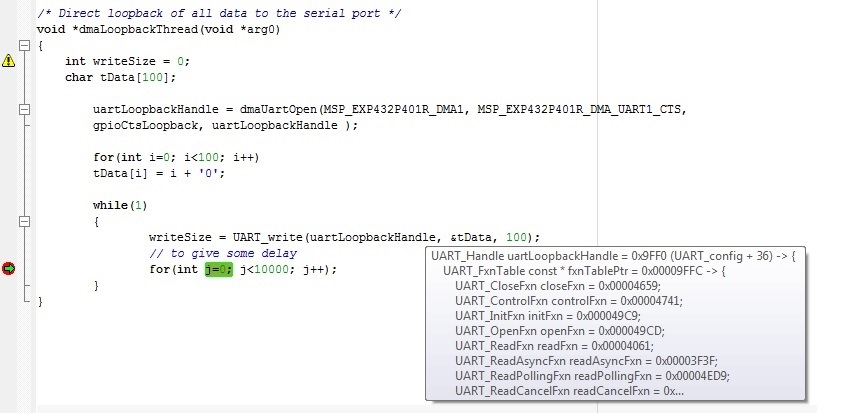
    Now I tried the dma_thread.c with a simple dmaLoopbackThread() as follow:

    I also wired GPIO P4.6 (DMA1 RTS) with GPIO P4.7 (DMA1 CTS). I tried to probe GPIO P2.7 on oscilloscope when executing UART_write(), but I do not see any activity. Did I miss out something?

    Would you be kind enough to give a simple application code to ensure simple UART_write and UART_readAsync loopback works functionally? 

    I would like to know if it is possible to remove RTS/CTS as this is not in our design. We only have a GPIO RTS coupled with message CTS.

  • I too had an issue where TX stopped when getting full, the TxPingPong was (is) causing greif.. I've backed out to my original TX (single transfer) method and kept the Rx ping pong as thats working great. I only pushed this to the repo this morning on the train. The previous version worked only with small sends and not approaching TX full. It would also lock up and NOT send after a while... I have given up making the Tx work in ping pong mode for the moment

    Check either the latest changes (this morning) and also check the latest ZIP i've uploaded to the branch. I've moved it across into my main application now and left some open issues and notes for futher completion.

    If you specify the RTS pointer assignment as NULL it will skip the asserting during execution, as it checks for != NULL before executing it. If you join the git project we can exchange issues and changes through there a little easier.

    full compile it on the launchpad board and run this on the auxiliary port with the loop connected between uart A2 and A1; Terminate with LF

    { "dmaChangePortSettings": [ 1500000, 10000] }

    { "dmaSendStream": 200 }

    I've added text output that will tell you when it calls Write, Read, Checks for sync, checks header etc.you will see the buffer wrap when small returns from read etc, using the asyn method.

    The CMD file i've written also pushes most UARTDMA routines to ram functions for added speed.

  • Hello Lucas,

    The "Typical Baud Rates and Errors" section for "Enhanced Universal Serial Communication Interface
    (eUSCI) – UART Mode" in the Technical Reference Manual provides RX and TX error rates for various baud rates. The table in this section covers error rates upto 460,800 baud. Based on this information it looks like the error rate for 1.5 MBaud could be pretty high and that might be what you are encountering.

    Thanks,
    Sai
  • Hi Sai,

    It was DMA congestion when using two eUSCI modules with my sample code at > 1.5MBit. I get good throughput with no errors with a single port at up to 2MBit. The throughput issues is now the transmit ping-pong code. I'm clearly not understanding something with the transmit side as the first setup of ping pong works, then the second stalls unless SW Triggerd. However triggering, or working out if I should trigger or not can cause a double write to the TXBuf and a single byte is thus not transmitted.

    I've settled with a straight TX DMA with done interrupt setup next transfer. This leaves gaps between transmissions and has a less than optimum flow back to application code filling up the transmit queue with more data.

    The customised RingBuf code works neatly to track pre-allocation and reservation for Tx and Rx DMA actions, allowing peaking into the Rx DMA (before the done interrupt) and wrapping the ring buffer nicely to eliminate at least one memcpy action on receive. I could technically insert a list of transmit bufferes which are references from application code space but that would require mods back into library code to handle the callbacks to release memory allocations while it continued on executing, whereas now it has a blocking call, so I'm not fussed (bluetooth library). Others may find this advantageous to have effectively a write through transmit assisted with DMA and a buffer hand back for receiver. The less copying the better..

    I'm running 1MBit on a 6MHz SMCLK at the moment and that seems just fine, its close to the edge and over my usual 8x sample/clock ratio where i'm comfortable, but OK. I may wind this back to 0.5MBit for my production code as I doublt I need such high throughput anyway.. It does however speed up startup of the cc2564 substantially.

    I'll continue to update my github with various mods that I'm finding useful. It would be a nice addition to see a DMA powered UART driver for MSP432, without the gumph of text parsing IMHO.

  • Hello Lucas,

    Lucas Oldfield said:
    I'll continue to update my github with various mods that I'm finding useful. It would be a nice addition to see a DMA powered UART driver for MSP432, without the gumph of text parsing IMHO.

    I will pass on this request to our development team. Thanks for all the feedback!

    Do you want me to keep this post open? Since there is not much activity here, I would like to close it.

    Thanks,

    Sai

  • I would think so.. I've posted a working example with DMA and >1.5MBit capability on github, and this proves that high baud rates are possible, even with low SMCLK speeds. 

    Not sure if you would like to include such a crazy implementation as an example of DMA, scatter gatherer and eUSCI combinations? google will send people here if they're looking for DMA and eUSCI on MSP432..

**Attention** This is a public forum