This thread has been locked.

If you have a related question, please click the "Ask a related question" button in the top right corner. The newly created question will be automatically linked to this question.

CCS/MSP430FR5969: MSP430FR5969 custom software update

Part Number: MSP430FR5969
Other Parts Discussed in Thread: MSPBSL

Tool/software: Code Composer Studio

Hi there,

I'm developing an application with MSP430FR5969, usind Code Composer Studio 7.4.

I need to provide an utility for "On field software update". I'm trying to understand if I can perform a software update without BSL utilities. 

Is there a way I can update the software with the .hex file generated by the compiler runtime? I'm planning to create a CUSTOM uart communication that would let a terminal (Teraterm)  send the .hex file and directly copy it to the onchip memory and create a custom code that will perform the software update so that it will be executed at startup: how can I do it? Are there examples as a reference?

Thank you

Regards

  • Hello Karles,

    What you are describing is a customer bootloader, or custom BSL.  All information on this topic and examples can be found at MSPBSL.  

    Since you are using UART, I would recommend using the built in BSL that already supports the UART interface.  Typically, customer BSLs are only required when trying to use a communication interface that is not already supported.  

    Either way, the first step would be to walk through the MSPBSL page Steps 1, 2, and then maybe 3.  Get your setup running with the built in BSL and BSL Scriptor and then you can customize the source if you still see a need to.  

    Thanks,

    JD

  • Hello JD,

    thank you for your answer,

    In my application I need to provide a custom "Bootloader" sw that will always start and let the final user be able to perform a SW application update with a Teraterm terminal. Also, the UARTs are already directly connected to other devices and I'm using the MSP430 I2C port to communicate with RS232 terminal through a I2C-> RS232 converter component.

    My company usually delivers a board with 2 softwares: custom bootlader (flashed into the device) and app (typically lunched by the custom bootloader). I already used this approach with other projects on TI DSPs applications.

    My goal would be to deliver the MSP with a custom bootlader flashed with JTAG. The custom bootlader should always start and will give an user interface through serial terminal that let the user do some basics low level function, including software update. If the user doesn't open a terimal the custom bootlader will start the main application itself.

    I would develop the custom bootlader and flash it into the MCU so that it will always start at system power on.

    I was thinking to compile the application program so that it will be placed on a specific FRAM memory range.

    Could it work if I create a custom linker cmd for the application sw so that it is all placed into FRAM2 as follow?

    If yes, can I just copy the .hex file into the FRAM2 address range?

    The bootlader sw will be limited into the FRAM memory range. The bootlader would let the application sw start by performing a jump to  _c_int00 application sw address.

    MEMORY
    {
    FRAM : origin = 0x4400, length = 0xBB80
    FRAM2 : origin = 0x10000,length = 0x4000
    }


    SECTIONS
    {
    "bootload" > FRAM

    .text > FRAM2
    .stack > FRAM2
    .bss > FRAM2
    .cinit > FRAM2
    .binit > FRAM2
    .far > FRAM2
    .fardata > FRAM2
    .rodata > FRAM2
    .neardata > FRAM2
    .const > FRAM2
    .switch > FRAM2
    .reset > FRAM2
    }

    -l msp430fr5969.cmd

    Thank you

    Regards

  • Hello Karles,

    Based on your feedback, you are on the right path and have the correct ideas here.    At first look without checking the datasheet, I think your linker file should work. 

    MSPBSL will remain your main resource page and I think following it will still be your easiest path.  I think these are the steps I would recommend to break down the process:

    Get the built-in BSL working 

    1. Get a "Main Memory" BSL in FRAM up and running, then modify.   
      1. MSP430FRBoot is a good starting point
      2. Get linker file configured and BSL located where you'd like
    2. Switch BSL interface from UART/SPI to I2C.
      1. Start customizing interface, but keep the working backend
    3. Replace MSPBSL function with your custom backend functionality  

    Another possible bump in the road is using ISRs in your BSL.  IE: Having an ISR for BSL and an ISR for application from a shared vector.  In this case, typically the ISR vector table is also moved to FRAM and managed by the BSL.  

    Useful App Notes:

    http://www.ti.com/lit/ug/slau550u/slau550u.pdf 

    http://www.ti.com/lit/an/slaa721b/slaa721b.pdf

    Good luck!

    JD

  • Thank you JD.

    I will work through your suggestions!

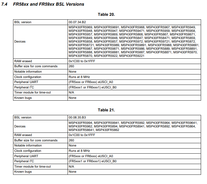
  • Is the UART BSL interface limited to eUSCI_A0 on fr5969? Is it possible to configure it to uUSCI_A1?

    Thank you!

  • Hello Karles,

    Looks like the UART inferface is limited to eUSCI_A on the FR5969 in the ROM BSL.  Below table is from section 7.4: http://www.ti.com/lit/ug/slau550u/slau550u.pdf  

    Thanks,

    JD  

**Attention** This is a public forum