This thread has been locked.

If you have a related question, please click the "Ask a related question" button in the top right corner. The newly created question will be automatically linked to this question.

MSP430FR2311: Erratum ADC65 applies?

Part Number: MSP430FR2311
Other Parts Discussed in Thread: MSP430FR5994, , ENERGYTRACE

I just tripped over Erratum ADC65 in the MSP430FR5994 Errata Sheet (SLAZ681M). This is the one where the ADC12 keeps running its clock between conversions.

I'm pretty sure I observed the same phenomenon in the MSP430FR2311 ADC some months back, but I don't see it described in the Errata Sheet (SLAZ679P). It was on a Rev A (not "X") device, and amounts to about 80uA (extra). I wouldn't be surprised if it happens on other FR2 devices, but all I have is "X" versions of those.

Should I report this to someone? I have a test program and some screen captures, but maybe the people who investigated ADC65 have something better.

This anomaly is perhaps more significant for the FR2 devices since they don't have DMA.

  • Hi Bruce,

    Thanks for your post. I will report this to the right person who will investigate your findings. Could you share your test program and screen captures?

  • The program samples 4 channels with a timer trigger and MSC=0, so each timer pulse triggers one sample cyclically. There's a compile-time constant which says whether to use CONSEQ=0 or 3. With CONSEQ=0, the ISR manipulates INCH directly to provide the channel cycling.

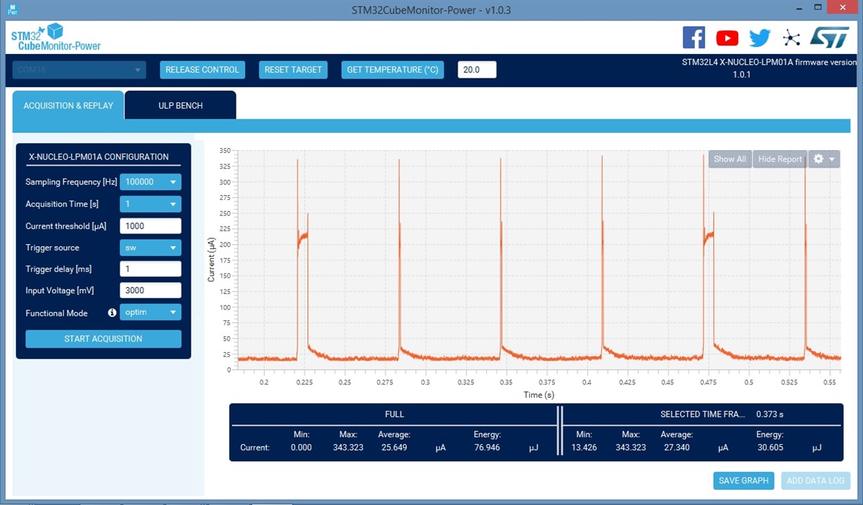
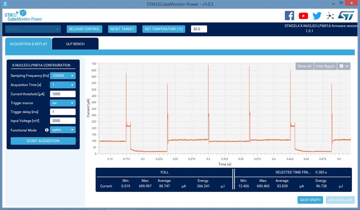
    The observation is that with CONSEQ=0, the idle time between samples is about 20uA (mostly REFO), as though the ADC has actually stopped. With CONSEQ=3, the idle time between channels 0 and 3 -- between bursts -- is about 20uA, but between the other channels -- mid-burst -- it's more like 100uA. The suggestion is that the ADC doesn't really shut down mid-burst.

    I suppose this could have been happening even back in the F2 series, but before the FR2 series there was some solution (multiple MEMs, DMA, DTC) to cycle channels in a true burst, so there was no occasion to do triggering this way, so I never looked.

    My notes (Nov 2018) say:

    ------------------------------------

    Notes on the figures:

    1. The ISR includes a “blip” using __delay_cycles. Each ISR spins for 1ms. The end-of-sequence ISR spins for an additional 5ms. Without these some of the ISRs were too short to be detected.

    2. The Y scales are different, since the CONSEQ=3 spikes were higher. There's probably a Truth in there somewhere.

    The measurements were obtained using an MSP430FR2311 (TSSOP) soldered to a breakout board, recorded using an LPM01A Energy Monitor board (V2.0), STM32CubeMonitor-Power software (v1.0.3).

    ------------------------------------

    Here's the trace with USE_CONSEQ=0:

    and this is with USE_CONSEQ=3:

  • Here is the program I used. The macro USE_CONSEQ is what makes the difference.

    ///
    //  adc-2311a
    //  See how much power sequence-of-channels takes.
    //
    #include <msp430.h> 
    #include <stdint.h>
    #define USE_REF         0       // Internal ref costs 60uA?
    #define USE_CONSEQ      3       // CONSEQ=3
    #define ADC_NCHAN       4       // See also ADCINCH_3 below
    uint16_t ADC_Result[ADC_NCHAN];
    volatile uint16_t i;
    int
    main(void)
    {
        WDTCTL = WDTPW | WDTHOLD;   // stop watchdog timer
        // Configure ADC A0-3 pins
        P1SEL0 |= BIT0 | BIT1 | BIT2 | BIT3;
        P1SEL1 |= BIT0 | BIT1 | BIT2 | BIT3;
    
        //  LED1/2. I ran a jumper from the P2.1 pin to J10.
        P2OUT &= ~(BIT0|BIT1);             // LED2 off
        P2DIR |=  (BIT0|BIT1);             //  output
    
        // Everything else input-pulldown
        P1OUT &= ~(BIT4|BIT5|BIT6|BIT7);
        P1REN |=  (BIT4|BIT5|BIT6|BIT7);
        P2OUT &= ~(BIT2|BIT3|BIT4|BIT5|BIT6|BIT7);
        P2REN |=  (BIT2|BIT3|BIT4|BIT5|BIT6|BIT7);
    
        PM5CTL0 &= ~LOCKLPM5;       //  Engage GPIOs
    
        // Configure ADC
        ADCCTL0 = ADCSHT_2 | (0*ADCMSC) | ADCON;  // 16ADCclks, ADC ON
    #if USE_CONSEQ == 0   // Check explicitly to avoid typos
        ADCCTL1 = ADCSHP | ADCSHS_2 | ADCCONSEQ_0 | ADCSSEL_0; // MODCLK, samp timer, TB1.1 trig, CONSEQ=0
    #elif USE_CONSEQ == 1
        ADCCTL1 = ADCSHP | ADCSHS_2 | ADCCONSEQ_1 | ADCSSEL_0; // MODCLK, samp timer, TB1.1 trig, CONSEQ=1
    #elif USE_CONSEQ == 3
        ADCCTL1 = ADCSHP | ADCSHS_2 | ADCCONSEQ_3 | ADCSSEL_0; // MODCLK, samp timer, TB1.1 trig, CONSEQ=3
    #else
    #error "Typo alert: USE_CONSEQ"
    #endif
        ADCCTL2 |= ADCSR;               // 50kHz is more than enough
        ADCMCTL0 |= ADCINCH_3 | ADCSREF_0;  // A0-3(EoS); Vref=Vcc
    #if USE_REF
        ADCMCTL0 |= ADCSREF_1;          // Vref=1.5V (we "know" ADCSREF_0==0)
    #endif
        ADCIE |= ADCIE0;                // Enable ADC conv complete interrupt
    
        //  Trigger from TB1.1 (ignore typos in SLASE58C Fig 6-4)
    #define PERIOD  (32768U/4/ADC_NCHAN) // Full group at 4Hz, pulse at 16Hz
        TB1CCTL1 = OUTMOD_3;             //  Set/Reset for short pulse
        TB1CCR1 = PERIOD-10;             //  short duty for no particular reason
        TB1CCR0 = PERIOD-1;              // Up Top
        TB1CTL = TBSSEL_1 | MC_0 | ID_0 | TBCLR; // ACLK, (Up), /1 (clear)
    
    #if USE_REF         // extra 60uA
        // Configure reference
        PMMCTL0_H = PMMPW_H;            // Unlock the PMM registers
        PMMCTL2 |= INTREFEN;            // Enable internal reference
        __delay_cycles(400);            // Delay for reference settling
        __no_operation();
    #endif
    
        i = ADC_NCHAN-1;                // ADCINCH_3
        ADCCTL0 |= ADCENC;              // Enable
        TB1CTL |= MC_1;                 // Start (Up)
        _EINT();
        while (1)
        {
            LPM3;                       // ADC ISR wakes us up every batch, about 4Hz
        }
        /*NOTREACHED*/
        return(0);
    }
    #pragma vector=ADC_VECTOR
    __interrupt void
    ADC_ISR(void)
    {
        switch(__even_in_range(ADCIV,ADCIV_ADCIFG))
        {
            case ADCIV_ADCIFG:
                ADC_Result[i] = ADCMEM0;
                __delay_cycles(1000);       // Blip the CPU power for the chart
                if(--i >= ADC_NCHAN)        // unsigned underflow? Start over
                {
                    __delay_cycles(5000);   // Bigger blip for the chart
                    P2OUT ^= BIT0;          // Toggle (LP) LED2
                    i = ADC_NCHAN-1;        // Always channels (N-1)..0
                    __bic_SR_register_on_exit(LPM3_bits); // Exit LPM0
    #if USE_CONSEQ == 1
                    ADCCTL0 &= ~ADCENC;     // Disable
                    ADCCTL0 |= ADCENC;      // Enable
    #endif
                }
    #if USE_CONSEQ == 0                 // Hand-type the INCH
                ADCCTL0 &= ~ADCENC;     // Disable
                ADCMCTL0 = (ADCMCTL0 & ~ADCINCH) | i;  // We "know" INCH is the LSb-s
                ADCCTL0 |= ADCENC;      // Enable
    #endif
                break;
            case ADCIV_NONE:
            case ADCIV_ADCOVIFG:
            case ADCIV_ADCTOVIFG:
            case ADCIV_ADCHIIFG:        // above high
            case ADCIV_ADCLOIFG:        // below low
            case ADCIV_ADCINIFG:        // in between
            default:
                 break;
        }
        return;
    }
    

  • Hi Bruce,

    Sorry for late reply.

    I have measured the current using your code and settings, but removing the LED2 connection to exclude it's impact.

    The power is measured by EnergyTrace in CCS. Since VCC supply is 3.3V, the current equals to power/3.3V.

    Here's the trace with USE_CONSEQ=0:

    Here's the trace with USE_CONSEQ=3:

  • It seems both the current in LPM3 and Active will increase with USE_CONSEQ=3. I will capture the TB1.1 and P2.0 toggle signal along with the current wave further.

  • Thanks for checking. The high average current was what tipped me off in the first place. I'm not sure EnergyTrace has the resolution to show everything, but with more detail it really seems like (quoting ADC65) "the ADC12_B always requests the ADC clock even between conversions."

    At the time, I wrote it off to "that's just the way it works" and moved on. When I saw ADC65, I wondered if maybe the Verilog Folk knew a way to fix it.

  • I did similar experiments with the G2553 (ADC10) and F5529 (ADC12_A), and as near as I can tell neither of them exhibits this behavior.

  • Thanks for your findings. It's very helpful. We need put more resources to go through the other devices.

  • I tried the FR2476. It displayed similar behavior to the FR2311. The intra-burst current was even higher (190uA for FR2476 vs 100uA for the FR2311), in spite of the lowered between-bursts level (2uA for the FR2476 vs 20uA for the FR2311). [They fixed the REFO. Excellent!]

    This is an "X" (not an "M") device, so I don't want to read too much into this.

  • Thanks for your deep investigation.

**Attention** This is a public forum