This thread has been locked.

If you have a related question, please click the "Ask a related question" button in the top right corner. The newly created question will be automatically linked to this question.

CCS/MSP432P401R: Verify when the P2.5 change the state

Part Number: MSP432P401R

Tool/software: Code Composer Studio

Hello I have face some problems because I am doing a routine and I need to know when the P2.5 change from the high to low or the low for high, can someone help me please. This is a piece of my code...

#define ADS1292_DRDY           BIT5

int main(void){
   P2->DIR &= ~(ADS1292_DRDY);                             /*SET THE ADS1292R DRDY PIN TO INPUT*/
    P2->REN |= ADS1292_DRDY;                                /*USE INTERNAL RESISTOR*/
    P2->OUT |= ADS1292_DRDY;                                /*THE INTERNAL RESISTOR IS PULL UP*/
    P2->IES |= ADS1292_DRDY;
    P2->IFG &= ~(ADS1292_DRDY);
    P2->IE &= ~(ADS1292_DRDY);
    while(1){
       if((P2->IN & ADS1292_DRDY) == false){
          // code
       }

  }

}

  • I don't see anything obviously wrong with this code fragment.

    What sort of problem are you seeing?

  • When my pin change a state the code inside (P2->IN & ADS1292_DRDY) == false) should be executed. And doesn't work

  • How do you know that P2.5 is changing state (specifically: going low)? 

    How do you know that that code block isn't being executed?

    (I'm supposing that false==0.)

  • yes, I Know because I call from some function that should change the state pin

  • I don't see any other function. How is it changing the pin? 

    The debugger can tell you the state of the pin. Besides the IN register, the IFG register will tell you whether it went low-then-high while you weren't looking.

  • I can Share with you my entire code...

    ads1292r.c
    #include <msp.h>
    
    #include <stdint.h>
    #include <stdbool.h>
    #include <stdio.h>
    #include <stdlib.h>
    #include <string.h>
    #include "main.h"
    #include "ads1292r.h"
    
    uint16_t SPI_TX_BUF[10];
    uint16_t SPI_RX_BUF[12], SPI_RX_COUNT = 0, SPI_RX_EXP_COUNT = 0;
    long ADS1292_ECG_DATA_BUFFER[6];
    extern uint16_t read_ADS1292R;
    extern volatile bool ADS1292R_RECEIVED_DATA;
    volatile uint16_t RX_Data = 0;
    
    uint16_t ecg_data_ready;


    #define DELAY_COUNT 2
    
    
    void ads1292_Init(void){
    
      ads1292_Reset();
    
      ads1292_DRDY_Interrupt();
    
      ads1292_ClockSelect();
    
      delayADS1292R(100);
    
      ads1292_Disable_Start();
    
      ads1292_Enable_Start();
    
      ads1292_Hard_Stop();
      delayADS1292R(100);
      ads1292_Start_Data_Conv_Command();
    
      ads1292_Soft_Stop();
      delayADS1292R(50);
      ads1292_Stop_Read_Data_Continuous();                  // SDATAC command
      delayADS1292R(300);
    
    
      ads1292_Reg_Write(ADS1292_REG_CONFIG1, 0x05);        // 500 SPS, read data continuous
      delayADS1292R(10);
      ads1292_Reg_Write(ADS1292_REG_CH2SET, 0xA0);      // lead-off comparators off, ref.buffer enabled, test signal disabled
      delayADS1292R(10);
      ads1292_Reg_Write(ADS1292_REG_LOFF, 0x10);           // lead-off disabled
      delayADS1292R(10);
      ads1292_Reg_Write(ADS1292_REG_CH1SET, 0x60);     // channel 1 enabled, gain 12, input is normal electrode
      delayADS1292R(10);
      ads1292_Reg_Write(ADS1292_REG_CH2SET, 0x60);     // channel 2 enabled, gain 12, input is normal electrode
      delayADS1292R(10);
      ads1292_Reg_Write(ADS1292_REG_RLDSENS, 0x2F);      // chop freq = fmod/16, RLD enabled, RLD inputs from channel 1 and 2
      delayADS1292R(10);
      ads1292_Reg_Write(ADS1292_REG_LOFFSENS, 0x00);       // LOFFSENS: default (disabled)
      delayADS1292R(10);
      ads1292_Reg_Write(ADS1292_REG_RESP1, 0xEA);      // CMOD/DEMOD turned ON, phase 112.5, internal clock for respiration
      delayADS1292R(10);
      ads1292_Reg_Write(ADS1292_REG_RESP2, 0x03);        // calibration on, respiration freq 32kHz, internal ref.voltage
      delayADS1292R(10);
    
      ads1292_Enable_Start();
    
      ads1292_Start_Read_Data_Continuous();
    
      delayADS1292R(10);
    
    
      printf("3c: %s\n","INITIALIZE REGISTERS");
    }
    
    
    void ADS1292R_Interface_Initialize(void){
        printf("3: %s\n","INITIALIZE INTERFACE");
        ads1292InitializePorts();
        ads1292SPIInterface_Initialize();
        ads1292_Init();
    
    }
    
    /*ADS1292R PORTS INITIALIZATION*/
    void ads1292InitializePorts(void){
        P2->DIR |= ADS1292_RESET | ADS1292_START | ADS1292_MAIN_CLKSEL;
        P2->OUT &= ~(ADS1292_RESET | ADS1292_START);
        P2->OUT |= ADS1292_RESET | ADS1292_MAIN_CLKSEL;
    
        P2->DIR |= ADS1292_SPI_CS;
        P2->OUT &= ~(ADS1292_SPI_CS);
        P2->OUT |= ADS1292_SPI_CS;
    
        printf("3a: %s\n","INITIALIZE PORTS");
    }
    
    /*ADS1292R SPI MASTER CONFIGURATION*/
    void ads1292SPIInterface_Initialize(void){
        P2->SEL0 |= ADS1292_SPI_SCK | ADS1292_SPI_DOUT | ADS1292_SPI_DIN | ADS1292_SPI_CS;
        P2->DIR  |= ADS1292_SPI_DOUT | ADS1292_SPI_DOUT;
        P2->DIR  &= ~(ADS1292_SPI_DIN);                    /*DIN AS INPUT*/
    
    
        EUSCI_A1->CTLW0 |= EUSCI_B_CTLW0_SWRST;            /*PUT eUSCI STATE MACHINE IN RESET*/
        EUSCI_A1->CTLW0  = EUSCI_A_CTLW0_SWRST |
                           EUSCI_B_CTLW0_MST   |           /*SET AS SPI MASTER*/
                           EUSCI_B_CTLW0_SYNC  |           /*SET AS SYNCHRONOUS MODE*/
                           EUSCI_B_CTLW0_CKPL  |           /*SET CLOCK POLARITY PHASE HIGH*/
                           EUSCI_B_CTLW0_MSB   |           /*MSB FIRST*/
                           EUSCI_A_CTLW0_MODE_1|           // 4-pin mode
                           EUSCI_A_CTLW0_STEM ;            // STE mode select
    
        EUSCI_A1->CTLW0 |= EUSCI_B_CTLW0_SSEL__SMCLK;      /*SMCLK*/
        EUSCI_A1->BRW = 0x0012;                            /*fBitClock = fBRCLK/(UCBRx+1)[~500KHz]*/
        EUSCI_A1->MCTLW = 0;                               /*NO MODULATION*/
        EUSCI_A1->CTLW0 &= ~(EUSCI_B_CTLW0_SWRST);         /*CLEAR SW RESET, RESUME OPERATION*/
    
        EUSCI_A1->IE |= EUSCI_A_IE_RXIE;
        printf("3b: %s\n","SPI'S");
    }
    /*DELAY MILISECONDS*/
    void delayADS1292R(int msec){
        int c;
        for(c=0;c<msec;c++);
    }
    /*CHOOSE INTERNAL CLOCK*/
    void ads1292_ClockSelect(void){
        P2->OUT |= ADS1292_MAIN_CLKSEL;
    }
    
    /*ADS1292R RESET CONFIGURATION*/
    void ads1292_Reset(void){
        P2->OUT |= ADS1292_RESET;                           /*RESET PIN HIGH*/
        delayADS1292R(100);                                /*WAIT 1 mSec*/
        P2->OUT &= ~(ADS1292_RESET);                        /*RESET PIN LOW*/
        delayADS1292R(100);                                /*WAIT 1 mSec*/
        P2->OUT |= ADS1292_RESET;                           /*RESET PIN HIGH*/
        delayADS1292R(100);                                /*WAIT 1 mSec*/
    }
    /*ADS1292R DISABLE START CONFIGURATION*/
    void ads1292_Disable_Start(void){
        P2->OUT &= ~(ADS1292_START);                        /*SET START PIN TO LOW*/
        /*SMALL DELAY TO SETTLE*/
        delayADS1292R(20);
    }
    /*ADS1292R ENABLE START CONFIGURATION*/
    void ads1292_Enable_Start(void){
        P2->OUT |= ADS1292_START;                           /*SET START PIN TO LOW*/
        /*SMALL DELAY TO SETTLE*/
        delayADS1292R(20);
    }
    
    /*ADS1292r CS ENABLE*/
    void ads1292_CS_Enable(void){
        P2->OUT |= ADS1292_SPI_CS;                              /*SET CS SPI TO HIGH*/
        delayADS1292R(100);
    }
    /*ADS1292r CS DISABLE*/
    void ads1292_CS_Disable(void){
        P2->OUT &= ~(ADS1292_SPI_CS);                           /*SET CS SPI TO LOW*/
    
    }
    /*ADS1292 DRDY INTERRUPT*/
    void ads1292_DRDY_Interrupt(void){
        P2->DIR  &= ~(ADS1292_DRDY);                           /*SET THE ADS1292R DRDY PIN TO INPUT*/
        P2->REN |= ADS1292_DRDY;                               /*USE INTERNAL RESISTOR*/
        P2->OUT |= ADS1292_DRDY;                               /*THE INTERNAL RESISTOR IS PULL UP*/
    
        P2->IES |= ADS1292_DRDY;                               /*LOW/HIGH EDGE*/
        P2->IFG &= ~(ADS1292_DRDY);                            /*CLEAR INTERRUPT FLAG*/
        P2->IE &= ~(ADS1292_DRDY);                             /*DISABLE INTERRUPT*/
    
    }
    /*ADS1292 ENABLE DRDY INTERRUPT*/
    void ads1292_Enable_DRDY_Interrupt(void){
        P2->IFG &= ~(ADS1292_DRDY);                           /*LOOKING FOR A FALLING EDGE*/
        P2->IE  |=  ADS1292_DRDY;                             /*ENABLE INTERRUPT*/
    }
    /*ADS1292 DISABLE DRDY INTERRUPT*/
    void ads1292_Disable_DRDY_Interrupt(void){
        P2->IE  &= ~(ADS1292_DRDY);                           /*DISABLE INTERRUPT*/
    }
    
    /*ADS1292R SPI COMMAND DATA*/
    void ads1292_SPI_Command_Data(uint16_t data){
      /*ADS1292r CS DISABLE*/
      ads1292_CS_Disable();
      /*SMALL DELAY TO SETTLE*/
      delayADS1292R(2);
      /*ADS1292r CS ENABLE*/
      ads1292_CS_Enable();
      /*SMALL DELAY TO SETTLE*/
      delayADS1292R(2);
      /*ADS1292r CS DISABLE*/
      ads1292_CS_Disable();
      /*SMALL DELAY TO SETTLE*/
      delayADS1292R(2);
    
      EUSCI_A1->TXBUF = data;
    
      while(EUSCI_A1->STATW & EUSCI_A_STATW_BUSY);
    
      EUSCI_A1->RXBUF;
      /*SMALL DELAY TO SETTLE*/
      delayADS1292R(2);
      printf("3c-command: %s\n","command data");
    }
    
    /*ADS1292 WAKE UP*/
    void ads1292_WAKE_UP(void){
        ads1292_SPI_Command_Data(WAKEUP);
    }
    /*ADS1292 STANDBY*/
    void ads1292_STANDBY(void){
        ads1292_SPI_Command_Data(STANDBY);
    }
    /*ADS1292 RESET*/
    void ads1292_2RESET(void){
        ads1292_SPI_Command_Data(RESET);
    }
    /*ADS1292 POWER DOWN ENABLE*/
    void ads1292_Power_Down_Enable(void){
        P2->OUT |= ADS1292_RESET;                           /*RESET PIN HIGH*/
    }
    /*ADS1292 POWER DOWN DISABLE*/
    void ads1292_Power_Down_Disable(void){
        P2->OUT &= ~(ADS1292_RESET);                        /*RESET PIN LOW*/
    }
    
    /*ADS1292 SOFTWARE START OR RESTART*/
    void ads1292_Soft_StartRestart(void){
        ads1292_SPI_Command_Data(START);
        ads1292_CS_Enable();
    }
    /*ADS1292 SOFTWARE HARD START OR RESTART*/
    void ads1292_Hard_StartRestart(void){
       P2->OUT |= ADS1292_START;
    
    }
    /*ADS1292 SOFTWARE START*/
    void ads1292_Soft_Start(void){
        ads1292_SPI_Command_Data(START);
    }
    /*ADS1292 SOFTWARE HARD START OR RESTART*/
    void ads1292_Hard_Stop(void){
       P2->OUT &= ~(ADS1292_START);
    }
    
    
    /*START DATA CONVERTION COMMAND*/
    void ads1292_Start_Data_Conv_Command(void){
      ads1292_SPI_Command_Data(START);                      /*SET 0x08 TO THE ADS1292R*/
    }
    /*STOP DATA CONVERTION COMMAND*/
    void ads1292_Soft_Stop(void){
      ads1292_SPI_Command_Data(STOP);                       /*SET 0x0A TO THE ADS1292R*/
    }
    /*START READ DATA CONTINUOUS*/
    void ads1292_Start_Read_Data_Continuous(void){
      ads1292_SPI_Command_Data(RDATAC);                     /*SET 0x10 TO THE ADS1292R*/
    }
    /*STOP READ DATA CONTINUOUS*/
    void ads1292_Stop_Read_Data_Continuous(void){
      ads1292_SPI_Command_Data(SDATAC);                     /*SET 0x11 TO THE ADS1292R*/
    }
    /*ADS1292 INIT*/
    void ads1292_4Init(void){
        ads1292_Reset();
        ads1292_Enable_Start();
        ads1292_Disable_Start();
    }
    
    /*ADS1292 CONVERSION*/
    void ads1292_Enable_Conversion(void){
        ads1292_Start_Read_Data_Continuous();
        ads1292_Hard_StartRestart();
    }
    
    /*ADS1292R REGISTER WRITE*/
    void ads1292_Reg_Write(uint16_t READ_WRITE_ADDRESS, uint16_t data){
        short i;
    
        switch(READ_WRITE_ADDRESS){
            case 1:
                data = data & 0x87;
            break;
            case 2:
                data = data & 0xFB;
                data |= 0x80;
            break;
            case 3:
                data = data & 0xFD;
                data |= 0x10;
            break;
            case 7:
                data = data & 0x3F;
            break;
            case 8:
                data = data & 0x5F;
            break;
            case 9:
                data |= 0x02;
            break;
            case 10:
                data = data & 0x87;
                data |= 0x01;
            break;
            case 11:
                data = data & 0x0F;
            break;
            default:
            break;
        }
    
        SPI_TX_BUF[0] = READ_WRITE_ADDRESS | WREG;
        SPI_TX_BUF[1] = 0;                                  /*WRITE SINGLE BYTE*/
        SPI_TX_BUF[2] = data;                               /*WRITE SINGLE BYTE*/
    
        for (i = 0; i<50; i++);
    
        EUSCI_A1->TXBUF = SPI_TX_BUF[0];                    /*SEND THE FIRST DATA TO THE TX BUFFER*/
        while(EUSCI_A1->STATW & EUSCI_A_STATW_BUSY);       /*POLLING TO SEE IF THE TX BUFFER IS READY?*/
        i = EUSCI_A1->RXBUF;                                /*READ RX BUFF*/
    
        EUSCI_A1->TXBUF = SPI_TX_BUF[1];                    /*SEND THE FIRST DATA TO THE TX BUFFER*/
        while(EUSCI_A1->STATW & EUSCI_A_STATW_BUSY);       /*POLLING TO SEE IF THE TX BUFFER IS READY?*/
        i =  EUSCI_A1->RXBUF;                               /*READ RX BUFF*/
    
        EUSCI_A1->TXBUF = SPI_TX_BUF[2];                     /*SEND THE FIRST DATA TO THE TX BUFFER*/
        while(EUSCI_A1->STATW & EUSCI_A_STATW_BUSY);        /*POLLING TO SEE IF THE TX BUFFER IS READY?*/
        i =  EUSCI_A1->RXBUF;                                /*READ RX BUFF*/
    
        delayADS1292R(2);
        ads1292_CS_Enable();
        printf("3c-data: %s\n","write data");
    }
    
    
    /*ADS1292R REGISTER READ*/
    uint16_t ads1292_Reg_Read (uint16_t REG_ADDRESS){
    
        uint16_t retValue;
    
        SPI_TX_BUF[0] = REG_ADDRESS | RREG;
        SPI_TX_BUF[1] = 0;
    
        ads1292_CS_Disable();
    
        EUSCI_A1->TXBUF = SPI_TX_BUF[0];                    /*SEND THE FIRST DATA TO THE TX BUFFER*/
        while(EUSCI_A1->STATW & EUSCI_A_STATW_BUSY);        /*POLLING TO SEE IF THE TX BUFFER IS READY?*/
    
        EUSCI_A1->TXBUF = SPI_TX_BUF[1];                    /*SEND THE FIRST DATA TO THE TX BUFFER*/
        while(EUSCI_A1->STATW & EUSCI_A_STATW_BUSY);        /*POLLING TO SEE IF THE TX BUFFER IS READY?*/
        retValue = EUSCI_A1->RXBUF;
    
        EUSCI_A1->TXBUF = 0x00;                             /*SEND THE FIRST DATA TO THE TX BUFFER*/
        while(EUSCI_A1->STATW & EUSCI_A_STATW_BUSY);        /*POLLING TO SEE IF THE TX BUFFER IS READY?*/
        retValue = EUSCI_A1->RXBUF;
    
        ads1292_CS_Enable();
    
        return retValue;
    }


    /*SPI INTERRUPT SERVICE ROUTINE*/
    void EUSCIA1_IRQHandler(void){
    
        if(EUSCI_A1->IE & EUSCI_A_IE_RXIE){
    
            RX_Data = EUSCI_A1->RXBUF;
            if(read_ADS1292R == true){
                printf("EUSCI: %s\n","A1");
                SPI_RX_BUF[SPI_RX_COUNT++] =  RX_Data;     /*STORE A  RESULT DATA I ARRAY*/
    
                if(SPI_RX_COUNT == SPI_RX_EXP_COUNT){
                    SPI_RX_COUNT = 0;
                    read_ADS1292R = false;
                    ADS1292R_RECEIVED_DATA = false;
                }
            }
    
    
        }
    }
    /*PORT x INTERRUPT SERVICE ROUTINE*/
    void PORT2_IRQHandler(void){
    
        if(P2->IFG &= ADS1292_DRDY){
            P2->IFG &= ~(ADS1292_DRDY);
            SPI_RX_COUNT = EUSCI_A1->RXBUF;
            SPI_RX_COUNT = 0;
            EUSCI_A1->TXBUF = 0;
            EUSCI_A1->IE |= EUSCI_A_IE_RXIE;
        }
    }
    
    void setDeviceOutBytes(void){
        SPI_RX_EXP_COUNT = 9;
    }
    

    ads1292r.h

    1731.main.c
    #include <msp.h>
    #include "main.h"
    #include "ads1292r.h"
    #include <stdio.h>
    #include <stdlib.h>
    #include <stdbool.h>
    #include <stdint.h>
    #include <string.h>


    uint16_t read_ADS1292R = 0;
    extern uint16_t SPI_RX_BUF[8];
    extern uint16_t SPI_RX_EXP_COUNT;
    volatile bool ADS1292R_RECEIVED_DATA = false;
    unsigned long uecgTemp = 0;
    signed long secgTemp = 0;
    volatile signed long s32DaqVals[8];
    uint16_t DataPacket[16];
    uint16_t dataLength = 8;
    
    
    int main(void){
        uint16_t i, j;
    
        watchdoghold();
        GPIOInterface_initGPIO();
        clock_System();                                                  /*MAKES SMCLK=12MHz*/
        ADS1292R_Interface_Initialize();
    
    
        __enable_irq();                                                  /*ENABLE GLOBAL INTERRUPT*/
    
        NVIC->ISER[0] = 1 << ((EUSCIA1_IRQn)& 31);                       /*ENABLE EUSCI_A1 INTERRUPT IN NVIC MODULE*/
        NVIC->ISER[1] = 1 << ((PORT2_IRQn)& 31);                         /*ENABLE PORT2 INTERRUPT IN NVIC MODULE*/
    
        while(1){
    
            if(!(P2->IN & ADS1292_DRDY)){                      /*VERIFY IF THE  DRDY PIN IS LOW*/
                printf("WHILE: %s\n","MAIN");
                read_ADS1292R  = true;                                   /*DATA IS READY TO SEND*/
                setDeviceOutBytes();
            }
            if(ADS1292R_RECEIVED_DATA == true){
                j=0;
                for(i=0;i<6;i+=3){                                      /*DATA OUTPUTS IS(24 STATUS + 24 RESPIRATION DATA + 24 ECG )*/
    
                    uecgTemp = (unsigned long)(((unsigned long)SPI_RX_BUF[i + 3] << 16) |
                                               ((unsigned long)SPI_RX_BUF[i + 4] <<  8) |
                                               ((unsigned long)SPI_RX_BUF[i + 4] <<  8));
    
                    uecgTemp = (unsigned long)(uecgTemp << 8);
                    secgTemp = (signed long)(uecgTemp);
                    secgTemp = (signed long)(secgTemp >> 8);
    
                    s32DaqVals[j++] = secgTemp;
                }
    
                DataPacket[0] = CES_CMDIF_PKT_START_1;
                DataPacket[1] = CES_CMDIF_PKT_START_2;
                DataPacket[2] = (uint16_t)(dataLength);
                DataPacket[3] = (uint16_t)(dataLength >> 8);
                DataPacket[4] = CES_CMDIF_TYPE_DATA;
                /*4 BYTES ECG DATA*/
                DataPacket[5] = s32DaqVals[1];
                DataPacket[6] = s32DaqVals[1] >> 8;
                DataPacket[7] = s32DaqVals[1] >> 16;
                DataPacket[8] = s32DaqVals[1] >> 24;
                /*4 BYTES RESPIRATION*/
                DataPacket[9] =  s32DaqVals[0];
                DataPacket[10] = s32DaqVals[0] >> 8;
                DataPacket[11] = s32DaqVals[0] >> 16;
                DataPacket[12] = s32DaqVals[0] >> 24;
                for(i=0; i<15; i++){
                    printf("dados.: %d\n",DataPacket[i]);
                }
                ADS1292R_RECEIVED_DATA = false;
                SPI_RX_EXP_COUNT = 0;
    
            }


        }/*END WHILE*/
    }
    
    
    void watchdoghold(void){
    
        WDTCTL = WDTPW + WDTHOLD;                                       /*STOP WATCHDOG TIMER*/
    
    }
    
    
    void GPIOInterface_initGPIO(void){
    
           P1->OUT = 0x00;  P1->DIR = 0x00;
           P2->OUT = 0x00;  P2->DIR = 0x00;
           P3->OUT = 0x00;  P3->DIR = 0x00;
           P4->OUT = 0x00;  P4->DIR = 0x00;
           P5->OUT = 0x00;  P5->DIR = 0x00;
           P6->OUT = 0x00;  P6->DIR = 0x00;
           P7->OUT = 0x00;  P7->DIR = 0x00;
           P8->OUT = 0x00;  P8->DIR = 0x00;
           P9->OUT = 0x00;  P9->DIR = 0x00;
           P10->OUT = 0x00; P10->DIR = 0x00;
           printf("1: %s\n","INIT GPIO");
    }
    
    /*
     * 24MHz/SMCLK = 2uS
     * 16 bits=> 2^16 = 65535;
     * With divde by 24 the timer clock will be 500 kHz timer clock
     *  The slowest period is 65535*2us=130ms, or about 8 Hz
     * */
    
    /*CLOCK SYSTEM CONTROL CONFIGURATION 24MHz*/
    void clock_System(void){
        CS->KEY  = CS_KEY_VAL;                               /*UNLOCK CS MODULE ACCESS*/
        CS->CTL0 = 0;                                        /*RESET TUNING PARAMETERS*/
        CS->CTL0 = CS_CTL0_DCORSEL_4;                        /*SET DCO TO 24MHz (NOMINAL CENTER OF 16-32MHz RANGE*/
    
        CS->CTL1 = CS->CTL1 & ~(CS_CTL1_SELS_MASK |          /*CLEAR EXISTING REGISTERS*/
                                  CS_CTL1_DIVS_MASK);
    
        CS->CTL1 = CS->CTL1 | (CS_CTL1_SELS_3 |              /*FOR SMCLK = DCO = 24MHZ*/
                                 CS_CTL1_DIVS_1);            /*FOR SMCLK =24MHz/2=12MHz*/
        CS->KEY = 0;                                         /*LOCK CS MODULE ACCESS*/
        printf("2: %s\n","CLOCK SYSTEM");
    }


    3107.main.h

  • Which function causes P2.5 to go low? What do P2->IN and P2->IFG say? I don't have one of these devices, so you'll have to do the diagnosis.

    I think you'll run into trouble using UCMODE=1 and UCSTEM=1, since that won't keep STE (/CS) asserted through the entire transaction. I recommend UCMODE=0, UCSTEM=0, and don't set SEL0 for the CS pin.

    You're setting UCCKPL=1 but the ADS1292R data sheet calls for CPOL=0.

  • So, I have to make the P2.5 to go low, this pin only goes low when finish the data transmition, this way I have to read when the P2.5 goes low to start send the data, and define how many bytes are ready to sent. I can make any diagnosis because the  function not even been read, I get your advice and changed the function to:

    void ads1292SPIInterface_Initialize(void){
        P2->SEL0 |= ADS1292_SPI_SCK | ADS1292_SPI_DOUT | ADS1292_SPI_DIN;
        P2->DIR  |= ADS1292_SPI_DOUT | ADS1292_SPI_DOUT;
        P2->DIR  &= ~(ADS1292_SPI_DIN);                    /*DIN AS INPUT*/
    
    
        EUSCI_A1->CTLW0 |= EUSCI_B_CTLW0_SWRST;            /*PUT eUSCI STATE MACHINE IN RESET*/
        EUSCI_A1->CTLW0  = EUSCI_A_CTLW0_SWRST |
                           EUSCI_B_CTLW0_MST   |           /*SET AS SPI MASTER*/
                           EUSCI_B_CTLW0_SYNC  |           /*SET AS SYNCHRONOUS MODE*/
                           EUSCI_B_CTLW0_CKPL  |           /*SET CLOCK POLARITY PHASE HIGH*/
                           EUSCI_B_CTLW0_MSB   ;           /*MSB FIRST*/
    
    
        EUSCI_A1->CTLW0 |= EUSCI_B_CTLW0_SSEL__SMCLK;      /*SMCLK*/
        EUSCI_A1->BRW = 0x0011;                            /*fBitClock = fBRCLK/(UCBRx+1)[~1000KHz]*/
        EUSCI_A1->MCTLW = 0;                               /*NO MODULATION*/
        EUSCI_A1->CTLW0 &= ~(EUSCI_B_CTLW0_SWRST);         /*CLEAR SW RESET, RESUME OPERATION*/
    
        EUSCI_A1->IE |= EUSCI_A_IE_RXIE;
        printf("3b: %s\n","SPI'S");
    }

    How you put the CPOL=0 on low?

  • Just remove the line with "EUSCI_B_CTLW0_CKPL", which will set (leave) CKPL=0.

    Reading the contents of P2->IN and P2->IFG will help you distinguish (a) DRDY never asserted and (b) DRDY asserted but the code missed it. Even better perhaps would be watching DRDY on a scope through the entire startup.

  • Hi armandoferr,

    How about your issue?

    Hi Bruce,

    Thank you very much for your support on E2E.

    Best Regards

    Johnson

  • Hello jonhson,

    I could not solve it ,I am having some difficulty in modeling my problem so that a function is called in the right place and causes the pin to change

  • Hi armandoferr,

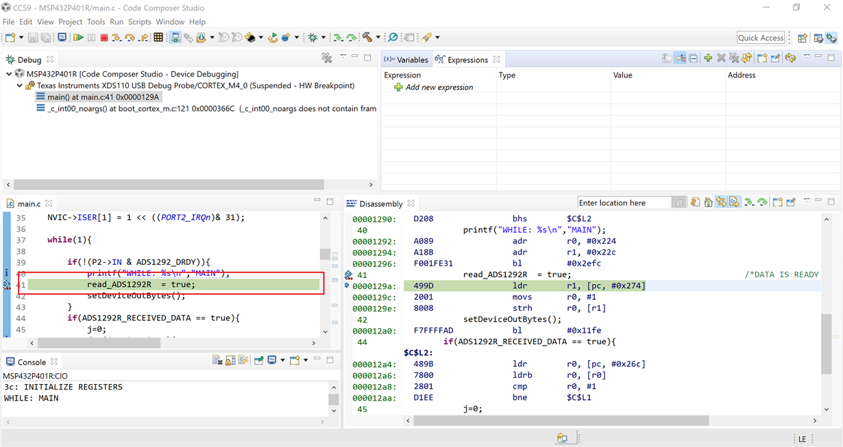
    I test the code up uploaded by you and found this setting about P2->BIT5 is normal, that can entry this code :

     if(!(P2->IN & ADS1292_DRDY)) { ... }


    Attach test image in debug mode:


    And other issue seems to be an application code problem, maybe you need to diagnosis the bug of user program.

    If you need any support about the MSP432 register, please describe the issue, purpose of program, test data and son on clearly.

    Some code example about SPI configuration in MSP432 MCU as your reference :

    http://dev.ti.com/tirex/explore/node?node=ABEAZlDMprmacNpMLdmkWw__z-lQYNj__LATEST

    Best Regards

    Johnson

  • Hello friend,

    I am trying to integrate msp432 with ads1292R, I have to control the state of the DRDY pin, to process the samples, that's is why I need control the pin state. I have made some modifications on SPI code, but the rest of code is the same.

                            EUSCI_A1->CTLW1 |= EUSCI_B_CTLW0_SWRST;                 /*PUT eUSCI STATE MACHINE IN RESET*/
                            EUSCI_A1->CTLW0  = EUSCI_B_CTLW0_MST   |                /*SET AS SPI MASTER*/
                                               EUSCI_B_CTLW0_MSB   |                /*MSB FIRST*/
                                               EUSCI_B_CTLW0_SYNC  ;                /*SET AS SYNCHRONOUS MODE*/
    
                            EUSCI_A1->CTLW1 |= EUSCI_B_CTLW0_SSEL__ACLK;           /*SMCLK*/
                            EUSCI_A1->BRW = 2;                                      /*fBitClock = fBRCLK/(UCBRx+1)[~500KHz]*/
                            EUSCI_A1->MCTLW = 0;                                    /*NO MODULATION*/
                            EUSCI_A1->CTLW1 &= ~(EUSCI_B_CTLW0_SWRST);              /*CLEAR SW RESET, RESUME OPERATION*/

  • > EUSCI_A1->CTLW1 |= EUSCI_B_CTLW0_SWRST;

    SWRST isn't in CTLW1, it's in CTLW0 (thus the name). Beyond what I suggested, I'm not sure there was anything wrong with your old SPI code.

    Do you know that DRDY is changing at all? If e.g. the ADS1292R isn't powering up properly you won't see anything. (I've already suggested 3 ways you can check this.)

  • Hi Armandoferr

    I haven’t heard from you for six days, so I’m assuming you were able to resolve your issue. If this isn’t the case, please click the "This did NOT resolve my issue" button and reply to this thread with more information. If this thread locks, please click the "Ask a related question" button and in the new thread describe the current status of your issue and any additional details you may have to assist us in helping to solve your issues.

    Best Regards,

    Johnson

  • This not resolve my issue.  One question how can I verify if a pin change their state, can anyone give me some example.

  • Hi armandoferr,

    In order to verify the status of a GPIO, you can view related registers in debug mode, such as P2-> IN or P2-> OUT, and you can also use the single-step function in Debug mode to diagnosis the problem you described.

    I tested your program in the previous reply, and it seems to be able to operate the GPIO port normally, so this problem seems to be the application issue that is communication with ADS1292. You can debug your code by single-step in debug mode and check your hardware circuits to solve the problem.

    Best Reagrds

    Johnson

**Attention** This is a public forum