This thread has been locked.

If you have a related question, please click the "Ask a related question" button in the top right corner. The newly created question will be automatically linked to this question.

MSP430G2553: Timer Capture Control

Part Number: MSP430G2553

I am trying to capture PWM output from the sensor board on P2.0 and P2.1 of the MSP430 board. I am able to capture for P2.1 but I am not getting the interrupt for P2.0

I need to capture both rising edge and falling edge. There are two inputs. Below is the code.

#include <msp430.h>

void UART_SendArray(char *TxArray);

int main(void)
{
    WDTCTL = WDTPW + WDTHOLD;                 // Stop WDT

    if (CALBC1_8MHZ==0xFF)                    // If calibration constant erased
    {
      while(1);                               // do not load, trap CPU!!
    }
    DCOCTL = 0;                               // Select lowest DCOx and MODx settings
    BCSCTL1 = CALBC1_8MHZ;                    // Set DCO to 8MHz
    DCOCTL = CALDCO_8MHZ;

    P1SEL = BIT1 | BIT2 ;                   // P1.1 = RXD, P1.2=TXD
    P1SEL2 = BIT1 | BIT2 ;                  // P1.1 = RXD, P1.2=TXD

    P2DIR &= ~(BIT0 | BIT1);                // P2.0 & P2.1 to Input Capture
    P2SEL |= BIT0 | BIT1;

    UCA0CTL1 |= UCSSEL_2;                   // SMCLK
    UCA0BR0 = 52;                           // 1MHz 9600
    UCA0BR1 = 0;                            // 1MHz 9600
    UCA0MCTL = UCBRS_0 + UCBRF_1 + UCOS16;            // Modulation UCBRSx = 1
    UCA0CTL1 &= ~UCSWRST;                   // **Initialize USCI state machine**
    IE2 |= UCA0RXIE;                        // Enable USCI_A0 RX interrupt

    // Configure the TA0CCR1 to do input capture
    TA1CCTL1 = CAP + CM_3 + CCIE + SCS + CCIS_0;
                                              // TA0CCR1 Capture mode; CCI1A; Both
                                              // Rising and Falling Edge; interrupt enable
    TA1CTL |= ID_3 + TASSEL_2 + MC_2 + TAIE;        // SMCLK, Cont Mode; start timer


    UART_SendArray("Uart Initialised!\r\n");

    while(1)
    {
        __bis_SR_register(LPM0_bits + GIE);

        __no_operation();
    }

}

// TA0_A1 Interrupt vector
#pragma vector = TIMER1_A1_VECTOR
__interrupt void TIMER1_A1_ISR (void)
{
  switch(__even_in_range(TA1IV, TA1IV_TAIFG))
  {
      case  TA1IV_NONE: break;              // Vector  0:  No interrupt
      case  TA1IV_TACCR1:
          UART_SendArray("Got A1_CCR1\r\n");
          __bis_SR_register_on_exit(LPM0_bits + GIE);
          break;                   // Vector  2:  TACCR1 CCIFG
      case  TA1IV_TACCR2:                   // Vector  2:  TACCR1 CCIFG
          UART_SendArray("Got A1_CCR2\r\n");
          __bis_SR_register_on_exit(LPM0_bits + GIE);
        break;
      case TA1IV_6: break;                  // Vector  6:  Reserved CCIFG
      case TA1IV_8: break;                  // Vector  8:  Reserved CCIFG
      case TA1IV_TAIFG: break;              // Vector 10:  TAIFG
      default:  break;
  }
}

void UART_SendArray(char *TxArray)
{
    while(*TxArray)
    {
        while (!(IFG2 & UCA0TXIFG));
        UCA0TXBUF = *TxArray++;
    }
}

If I try "case  TA1IV_TACCR0" it gives a compile error. Is it because CCR1 has the highest priority so I cannot get the CCR2? Please help. I am using Timer0 for other purpose so I need to use Timer1. I am testing this of the G2553 but I want to implement it on FR6989 finally.

Regards

Vijay

  • Hi Vijay,

    In your program, you don't set TA1CCTL2 register, you need to add this code:

    // Configure the TA0CCR2 to do input capture
        TA1CCTL2 = CAP + CM_3 + CCIE + SCS + CCIS_0;
                                                  // TA0CCR2 Capture mode; CCI1A; Both
                                                  // Rising and Falling Edge; interrupt enable

    Best Regards

    Johnson

  • I added the code as you advised. Now I am still only able to get CCR1. I want to get both rising edge and falling edge. Please advise me how to do it.

    #pragma vector = TIMER1_A1_VECTOR
    __interrupt void TIMER1_A1_ISR (void)
    {
      switch(__even_in_range(TA1IV, TA1IV_TAIFG))
      {
          case  TA1IV_NONE: break;              // Vector  0:  No interrupt
          case  TA1IV_TACCR1:
              UART_SendArray("Got A1_CCR1\r\n");
              break;
    
          case  TA1IV_TACCR2:
              UART_SendArray("Got A1_CCR2\r\n");
              break;
    
          case TA1IV_6: break;                  // Vector  6:  Reserved CCIFG
          case TA1IV_8: break;                  // Vector  8:  Reserved CCIFG
          case TA1IV_TAIFG: break;              // Vector 10:  TAIFG
          default:  break;
      }
    }

  • Hi Vijay,

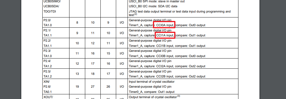
    The pin 2.0 function is CCI0A, and pin 2.1 function is CCI1A, as follow:

    Thus you should setting TA1CCTL0 and TA1CCTL1 register, like this :

    // Configure the TA1CCR0 to do input capture
        TA1CCTL0 = CAP + CM_3 + CCIE + SCS + CCIS_0;
                                                  // TA1CCR0 Capture mode; CCI0A; Both
                                                  // Rising and Falling Edge; interrupt enable
    // Configure the TA1CCR1 to do input capture
        TA1CCTL1 = CAP + CM_3 + CCIE + SCS + CCIS_0;
                                                  // TA1CCR1 Capture mode; CCI1A; Both
                                                  // Rising and Falling Edge; interrupt enable

    At the same time, the interrupt vector of CCR0 is independent of other interrupts (you can refer to user's guide). The interrupt vector corresponding to CCR0 is TIMER1_A0_VECTOR, and the other interrupts are TIMER1_A1_VECTOR, so you need the following interrupt program:

    // TA1_A0 Interrupt vector
    #pragma vector=TIMER1_A0_VECTOR
    __interrupt void TIMER1_A0_ISR (void)
    {
        UART_SendArray("Got A1_CCR0\r\n");
        __bic_SR_register_on_exit(LPM0_bits + GIE);  // Exit LPM0 on return to main
    }
    
    // TA1_A1 Interrupt vector
    #pragma vector = TIMER1_A1_VECTOR
    __interrupt void TIMER1_A1_ISR (void)
    {
      switch(__even_in_range(TA1IV,0x0A))
      {
          case  TA1IV_NONE: break;              // Vector  0:  No interrupt
          case  TA1IV_TACCR1:                   // Vector  2:  TACCR1 CCIFG
                UART_SendArray("Got A1_CCR1\r\n");
                __bic_SR_register_on_exit(LPM0_bits + GIE);  // Exit LPM0 on return to main
            break;
          case TA1IV_TACCR2: break;             // Vector  4:  TACCR2 CCIFG
          case TA1IV_6: break;                  // Vector  6:  Reserved CCIFG
          case TA1IV_8: break;                  // Vector  8:  Reserved CCIFG
          case TA1IV_TAIFG: break;              // Vector 10:  TAIFG
          default:  break;
      }
    }

    Some data about Interrupt as your reference :

    And other ways, maybe you can select pin2.4 function as input capture( CCI2A), this is more simple.

    Best Regards

    Johnson

  • In CCS, TACCR0 refers to 

    #define TACCR0                 TA0CCR0        /* Timer A Capture/Compare 0 */

    With the code you have advised I am only able to capture P2.0. But if I disable the TA1CCTL0 then I am able to capture P2.1.

    Uart Initialised!
    Got A1_CCR0
    Got A1_CCR0
    Got A1_CCR0
    Got A1_CCR0
    Got A1_CCR0
    Got A1_CCR0
    Got A1_CCR0
    Got A1_CCR0

  • I used P2.1 and P2.4 with below code and it worked. Dont know why it did not work with P2.0.

    TA1CCTL1 = CAP + CM_3 + CCIE + SCS + CCIS_0;
    TA1CCTL2 = CAP + CM_3 + CCIE + SCS + CCIS_0;

    Thanks for the help.

  • I am still struggling with the capture of the PWM signals from P2.1 and P2.4. Below is the code.

    #include <msp430.h>
    #include <stdio.h>
    
    char Sensor1[20] = {0};
    char Sensor2[20] = {0};
    
    unsigned int First, RE1, RE2, FE1, RE3, RE4, FE2, Count1, Count2 = 0;
    unsigned int First1, First2 = 1;
    unsigned int flag1,flag2 = 0;
    
    void UART_SendArray(char *TxArray);
    
    int main(void)
    {
        WDTCTL = WDTPW + WDTHOLD;               // Stop WDT
    
        P1SEL = BIT1 | BIT2 ;                   // P1.1 = RXD, P1.2=TXD
        P1SEL2 = BIT1 | BIT2 ;                  // P1.1 = RXD, P1.2=TXD
    
        P2DIR &= ~(BIT1 | BIT4);                // P2.0 & P2.1 to Input Capture
        P2SEL |= BIT1 | BIT4;
    
        if (CALBC1_8MHZ==0xFF)                  // If calibration constant erased
        {
          while(1);                             // do not load, trap CPU!!
        }
        DCOCTL = 0;                             // Select lowest DCOx and MODx settings
        BCSCTL1 = CALBC1_8MHZ;                  // Set DCO to 8MHz
        DCOCTL = CALDCO_8MHZ;
    
        UCA0CTL1 |= UCSSEL_2;                   // SMCLK
        UCA0BR0 = 52;                           // 1MHz 9600
        UCA0BR1 = 0;                            // 1MHz 9600
        UCA0MCTL = UCBRS_0 + UCBRF_1 + UCOS16;            // Modulation UCBRSx = 1
        UCA0CTL1 &= ~UCSWRST;                   // **Initialize USCI state machine**
        IE2 |= UCA0RXIE;                        // Enable USCI_A0 RX interrupt
    
        UART_SendArray("Uart Initialised!\r\n");
    
        // Configure the TA0CCR1 to do input capture
        TA1CCTL1 = CAP + CM_3 + SCS + CCIS_0;    // TA1CCR1 & TA1CCR2 Capture mode; CCI1A; Both
        TA1CCTL2 = CAP + CM_3 + SCS + CCIS_0;    // Rising and Falling Edge; interrupt enable
        TA1CTL |= TASSEL_2 + MC_2 + TACLR;        // SMCLK, Cont Mode; start timer
    
        while(1)
        {
            TA1CCTL1 |= CCIE;
            TA1CCTL2 |= CCIE;
            TA1CTL |= TACLR;
            __bis_SR_register(LPM0_bits + GIE);
            if(flag1 == 1)
            {
                sprintf(Sensor1, "R1: %d R2: %d F1: %d\r\n", RE1, RE2, FE1);
                UART_SendArray(Sensor1);
                flag1 = 0;
                Count1 = 0;
            }
            if(flag2 == 1)
            {
                sprintf(Sensor2, "R3: %d R4: %d F2: %d\r\n\r\n", RE3, RE4, FE2);
                UART_SendArray(Sensor2);
                flag2 = 0;
                Count2 = 0;
            }
            __delay_cycles(40000000);
        }
    }
    
    // TA1_A3 Interrupt vector
    #pragma vector = TIMER1_A1_VECTOR
    __interrupt void TIMER1_A1_ISR (void)
    {
        switch(__even_in_range(TA1IV, TA1IV_TAIFG))
        {
            case  TA1IV_NONE: break;              // Vector  0:  No interrupt
            case  TA1IV_TACCR1:                   // Vector  2:  TA1CCR1 CCIFG
                if(!(TA1CCTL1 & COV))
                {
                    if(TA1CCTL1 & CCI)                 // Capture Input Pin Status
                    {
                      // Rising Edge was captured
                      if(!Count1)
                      {
                          RE1 = TA1CCR1;
                          Count1++;
                      }
                      else
                      {
                          RE2 = TA1CCR1;
                          TA1CCTL1 &= ~CCIE;
                          Count1 = 0;
                          flag1 = 1;
                      }
                      if(First1)
                          First1 = 0;
                    }
                    else
                    {
                      // Falling Edge was captured
                      if(!First1)
                      {
                          FE1 = TA1CCR1;
                      }
                    }
                    break;
                }
                else
                {
                    TA1CCTL1 &= ~COV;
                }
            case TA1IV_TACCR2:             // Vector  4:  TA1CCR2 CCIFG
                if(!(TA1CCTL2 & COV))
                {
                    if(TA1CCTL2 & CCI)                 // Capture Input Pin Status
                    {
                        // Rising Edge was captured
                        if (!Count2)
                        {
                            RE3 = TA1CCR2;
                            Count2++;
                        }
                        else
                        {
                            RE4 = TA1CCR2;
                            TA1CCTL2 &= ~CCIE;
                            Count2 = 0;
                            flag2 = 1;
                            __bic_SR_register_on_exit(LPM0_bits + GIE);  // Exit LPM0 on return to main
                        }
                        if(First2)
                            First2 = 0;
                    }
                    else
                    {
                        // Falling Edge was captured
                        if(!First2)
                        {
                            FE2 = TA1CCR2;
                        }
                    }
                    break;
                }
                else
                {
                    TA1CCTL2 &= ~COV;
                }
            case TA1IV_6: break;                  // Vector  6:  Reserved CCIFG
            case TA1IV_8: break;                  // Vector  8:  Reserved CCIFG
            case TA1IV_TAIFG: break;              // Vector 10:  TA1IFG
            default:  break;
        }
    }
    
    void UART_SendArray(char *TxArray)
    {
        while(*TxArray)
        {
            while (!(IFG2 & UCA0TXIFG));
            UCA0TXBUF = *TxArray++;
        }
    }
    

    I have tried several different ways by enabling interrupts and disabling interrupts and also leaving the interrupts constantly on. Whatever I do I am getting erratic timer count. Below is the output.


    R1: 5310 R2: -23062 F1: 10

    R3: -23062 R4: 13308 F2: 0

    R3: -26184 R4: -26184 F2: 0

    R1: 5310 R2: 13375 F1: 10
    R3: 13639 R4: 17288 F2: 13692

    R3: 4570 R4: 30129 F2: 10

    R1: 5310 R2: -19970 F1: 3338
    R3: -19758 R4: 16464 F2: 10

    R1: 5310 R2: 62 F1: 10
    R3: 62 R4: 420 F2: 10

    R1: 929 R2: 1668 F1: 982
    R3: 1931 R4: 2444 F2: 1982


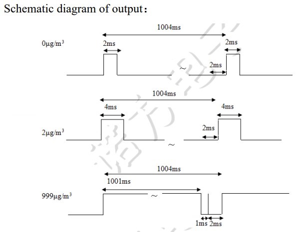
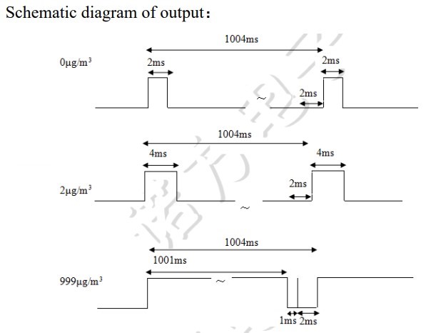
    The total period from R1 to R2 and R3 to R4 should be 1004ms +1%. The F1-R1 and F2-R3 is the duty cycle. Please help with the code and the calculation. Also help with reading the both pins consecutively every 10 secs.

  • 1) There's no "break" between the two TA1CCRx cases in the ISR, so a CCR1 interrupt always thinks there's a CCR2 interrupt as well.

    2) You probably want "%u"  rather than "%d" in the printf formats

    But the real problem is:

    3) With SMCLK=8MHz and ID=0, you can only time up to 64K/8= ~8msec. Your longest pulse (and period) is about 125 times that, so the timer is wrapping back to 0 (repeatedly). Even with SMCLK=1MHz and ID=3 you only get 500+ms.

    The simplest solution is to install a 32kHz crystal and use ACLK instead of SMCLK. That will give you a 2-second timer cycle to work with. (The VLO is probably much too sloppy for this.)

    The pure-software solution -- trying to count timer overflows along with capture -- is harder than it looks. It mostly works fine until some edge arrives near an overflow.

    How precise do your measurements need to be? If counting milliseconds is enough, just make a software millisecond timer (increment a variable every 8000 ticks) and do the "capture" with a GPIO interrupt. [Edit: I think you could actually continue to use the timer (rather than GPIO) for capture -- just ignore the CCR values.]

  • Hi Vijay,

    How about your issue?

    Best Regards

    Johnson

  • I don't have a crystal on the G2553. I am trying to get it soldered. Will post when I am done with it.

  • I have FR6989 launchpad. Can I use P1.4 and P2.0 for input signal from PWM source or do I need to use ADC read pins?

  • P1.4 and P2.0 are both timer inputs, but on different timers (TA1 vs TB0). You might do better with P1.6/7 (TA0.1/2). [Ref DS (SLAS789D) Tables 6-21/22]

  • I am planning to use P2.4 and P2.5 on the FR6989 launchpad. Please let me if below code is correct way to configure the P2.4 AND P2.5 for input capture.

    // Configure the TB0CCR3, TB0CCR4 on P2.4 & P2.5 to do input capture
    P2SEL0 |= BIT4 | BIT5;
    P2SEL1 &= ~(BIT4 | BIT5);
    
    TB0CCTL3 = CAP + CM_3 + SCS + CCIS_0;    // TB0CCR3 & TB0CCR4 Capture mode; CCI3A, CCI4A; Both
    TB0CCTL4 = CAP + CM_3 + SCS + CCIS_0;    // Rising and Falling Edge; interrupt enable
    TB0CTL |= TASSEL_1 + MC_2 + TBCLR;        // ACLK, Cont Mode; start timer


  • Looks OK from here. I don't see CCIE being set, but if you set it later that's fine.

    P2.4/5 are listed as COMx pins, but they don't seem to be connected to the Launchpad LCD so I don't expect any interference.

    (Someone will probably mention that you ought to use TBSSEL_1, but yes it's exactly the same as TASSEL_1. Indeed, the only difference in the TimerA/B  bits is that they took away SCCI (TA) in order to place CLLD (TB) in those bits.)

  • // TB0 Interrupt vector
    #pragma vector = TIMERB1_VECTOR
    __interrupt void TIMERB1_ISR (void)
    {
        switch(__even_in_range(TB0IV, TB0IV_TBIFG))
        {
        case  TB0IV_TBCCR3:
            if(!(TB0CCTL3 & COV))
            {
                if(TB0CCTL3 & CCI)                 // Capture Input Pin Status
                {
                  // Rising Edge was captured
                  if(!Count1)
                  {
                      RE1 = TB0CCR3;
                      Count1++;
                  }
                  else
                  {
                      RE2 = TB0CCR3;
                      TB0CCTL3 &= ~CCIE;
                      Count1 = 0;
                      flag1 = 1;
                  }
                  if(First1)
                      First1 = 0;
                }
                else
                {
                  // Falling Edge was captured
                  if(!First1)
                  {
                      FE1 = TB0CCR3;
                  }
                }
            }
            else
            {
                TB0CCTL3 &= ~COV;
            }
            break;
        case  TB0IV_TBCCR4:
            if(!(TB0CCTL4 & COV))
            {
                if(TB0CCTL4 & CCI)                 // Capture Input Pin Status
                {
                  // Rising Edge was captured
                  if(!Count2)
                  {
                      RE3 = TB0CCR4;
                      Count2++;
                  }
                  else
                  {
                      RE4 = TB0CCR4;
                      TB0CCTL4 &= ~CCIE;
                      Count2 = 0;
                      flag2 = 1;
                      __bic_SR_register_on_exit(LPM0_bits + GIE);  // Exit LPM0 on return to main
                  }
                  if(First2)
                      First2 = 0;
                }
                else
                {
                  // Falling Edge was captured
                  if(!First2)
                  {
                      FE2 = TB0CCR4;
                  }
                }
            }
            else
            {
                TB0CCTL4 &= ~COV;
            }
            break;
        }
    }

    RESULTS:

    R1: 2560 R2: -16035 F1: -16036
    R3: -16034 R4: -16022 F2: -16026

    R1: 2573 R2: 18634 F1: 12342
    R3: 18634 R4: 18636 F2: 13874

    R1: 2573 R2: -12310 F1: 3380
    R3: -12280 R4: -12279 F2: 3338

    R1: 2560 R2: 22385 F1: 14387
    R3: 22387 R4: 22388 F2: 2573

    I got the above output with ACLK. Are the negative values OK. I don't seem to be getting the right values. How do I convert them to micrograms?

  • You can avoid the negative (display) values by using "%u" rather than "%d". When you start using this, you'll be working with (unsigned) differences, and unsigned subtraction will take care of the rollovers. My calculator says that e.g. -16035 is 49502.

    With a 32kHz clock, one second is 32768 ticks, so that's roughly what you should see between successive rising edges (R2-R1 e.g.). Instead, you're seeing large values on one channel and small ones on the other.

    1) Do you have any way to independently verify the signal(s) your device is actually sending? A scope would be good, but with such long cycles you could probably contrive something with the Launchpad LEDs. (I always believe data sheets .... until I don't.)

    2) Do you ever see COV set? On the one hand it seems unlikely, on the other hand if you did you might see odd results. It might be worth monitoring with a breakpoint or an LED.

    3) Most of the graphs you showed in the original post look reasonable, except the last (very high measurement), which has that disconcerting spike at the end. Is there any chance you're encountering that case?

    Unrelated: In your earlier post the SensorN[] arrays are much too short (should be more like 40 than 20). I recommend snprintf() rather than sprintf(). And make the arrays bigger as needed.

  • 2019-11-24	20:27:41	PM 10	174.5 µg/m3	PM 2.5	100.9 µg/m3
    2019-11-24	20:27:42	PM 10	173.6 µg/m3	PM 2.5	100.7 µg/m3
    2019-11-24	20:27:43	PM 10	172.8 µg/m3	PM 2.5	100.4 µg/m3
    2019-11-24	20:27:44	PM 10	172.9 µg/m3	PM 2.5	100.3 µg/m3

    It is a serial output from the sensor device.

    The above is from the sensor datasheet. I have not posted any graphs earlier. Please let me what you meant by the graphs in the orginal post.

    Also when I try to use %u, there is no output of values but I get output using %d. All the variables are declared as unsigned integers

  • Yes, it's that third graph (999ug)  that was disconcerting -- I suspect that little spike at the end will get in your way eventually. Does the book say at what level that spike appears?

    You may need to set printf=nofloat to get "%u". In CCSv8 this is "Build Settings->Compiler->Advanced->Language->Level of printf"

    I went back over the books, and, although the Launchpad crystal is connected, the FR6989 doesn't automatically start the LFXT (and there's no REFO). You'll need to add something like:

        FRCTL0 = FRCTLPW | NWAITS_0; // No-op to get rid of that warning
        PJSEL0 |= (BIT4|BIT5);      // PJ.4/5 as LFXT per SLAS789C Table 6-40
        CSCTL0_H = 0xA5;            // Password to unlock
        CSCTL4 &= ~(LFXTBYPASS | LFXTOFF); // Make sure LFXT is on
        while (CSCTL5 & LFXTOFFG)   // Keep clearing fault
        {
            CSCTL5 &= ~LFXTOFFG;    // Here
            SFRIFG1 &= ~OFIFG;      //  and here
        }                           //  until it clears
        CSCTL0_H = 0x00;            // Re-lock

    to get it going. 

    [Edit: Removed the comment about the clock error -- it's more likely that was from a DCO error in my generated input.]

  • Below is the code I am using for ACLK

        // Init LFXT Pins
        PJSEL0 = BIT4 | BIT5;                   // PJ.4(LFXIN), PJ.5(LFXOUT)
    
       // Configure LFXT 32kHz crystal
        CSCTL0_H = CSKEY >> 8;                                      // Unlock CS registers
    
        CSCTL1 = DCOFSEL_3 | DCORSEL;                               // Set DCO to 8MHz
        CSCTL2 = SELA__LFXTCLK | SELS__DCOCLK | SELM__DCOCLK;
        CSCTL3 = DIVA__1 | DIVS__1 | DIVM__1;                       // Set all dividers
    
        // Configure LFXT 32kHz crystal
        CSCTL4 &= ~LFXTOFF;                                         // Enable LFXT
        do
        {
          CSCTL5 &= ~LFXTOFFG;                                      // Clear LFXT fault flag
          SFRIFG1 &= ~OFIFG;
        } while (SFRIFG1 & OFIFG);                                  // Test oscillator fault flag
    
        CSCTL0_H = 0;                                               // Lock CS registers

    i have enabled printf support to full since I will need float for calculations later. Below is the output which is nowhere near what I am expecting.

    R1: 38558 R2: 6564 F1: 38557
    R3: 6564 R4: 6565 F2: 35184
    
    R1: 40988 R2: 40990 F1: 38557
    R3: 40988 R4: 40990 F2: 35184
    
    R1: 10154 R2: 10155 F1: 10153
    R3: 10154 R4: 10155 F2: 10153
    
    R1: 44686 R2: 44688 F1: 10153
    R3: 44686 R4: 44688 F2: 10153
    
    R1: 13878 R2: 13880 F1: 13879
    R3: 13881 R4: 13882 F2: 13880

    There not much information in the data sheet. I have attached it for your reference.

    SDS011-DATASHEET.pdf

  • Some more readings
    
    R1: 26332 R2: 26333 F1: 57288
    R3: 26332 R4: 26334 F2: 26333
    
    R1: 60861 R2: 60862 F1: 57288
    R3: 60861 R4: 60862 F2: 26333
    
    R3: 30112 R4: 30113 F2: 30111
    
    R1: 30113 R2: 63863 F1: 63862
    R3: 63861 R4: 63864 F2: 63863
    
    R1: 32864 R2: 32865 F1: 63862
    R3: 32864 R4: 32865 F2: 63863

  • As I recall (I don't have it here), the only substantive change I made was to initialize "first1" to 1 rather than 0. The effects of this should disappear after the first round.

    But I also added a synthesized PWM signal (TA0.1-2) which I patched into the capture channels on TB0. I got reasonable results, which suggests there's something funny about the signal from the (real) sensor.

    I agree the data sheet is a bit "thin". The 5V/(70+10)mA is disturbing. (1) Older Launchpads couldn't supply 80mA extra (I don't know about this one). (2) If you're powering it at 5V, that probably means that the PWM is running at 5V, which is out of spec for the input pins. How do you have this wired?

    If you don't have a scope, I suspect you could just patch one of the PWM outputs to one of the Launchpad LED headers (replace P1.0, e.g.). The LEDs are active high, so you should be able to get a crude sense of what the signal actually looks like.

  • It looks like there is a signal issue from PWM outputs. I am giving up on this. But for academic interest I am posting the PWM outputs on the multi meter for you. 

    Click here to play this video

**Attention** This is a public forum