This thread has been locked.

If you have a related question, please click the "Ask a related question" button in the top right corner. The newly created question will be automatically linked to this question.

MSP430FR2311: FLL appears not to lock, everything on auto, REFO used, MODCLK set at 4MHz, but off by 12%, THREE EDITS

Part Number: MSP430FR2311

Hi Forum,

Maybe I am reading the specs wrong. The following table, while referencing 16MHz, seems to indicate a lock frequency much closer to the target than I am getting. Two launchpads are being used, this one using REFO, and the other using XT1, and both exhibit the same results. Both MCLK freqs are down 10% to 12%. The spec sheet shows.....

%1.0%FLL lock frequency,16 MHz,–40°C to 85°C–2.0%2.0%, while the XT1 spec shows +- 0.5%.

***********************************************

THIS IS AN EDIT TO THIS POST: Just want to add a couple of details Both ACLK and SMCLK were mapped to the header pins on both launch pads. Both REFO and XT1 are spot-on when checked with an oscope. SMCLK (and hence MDCLK) are 10 to 12% long in period. When REFO and XT1 are used as a timer base, and LED's are used to blink at exactly 1sec, both pass the "clock-on-the-wall" click test, an aveage over 10 seconds. SMCLK fails the "clock-on-the-wall" click test (I can hear the clock tick as it goes around). Not exactly scientific, but it works.

THIS IS THE SECOND EDIT TO THIS POST: Bits 9,8 of CSCTL7 were polled and resulted in 10, DCOCLK IS CURRENTLY TOO FAST, which indicates FLL UNLOCK. Both bits would have to have returned 0 to show that the FLL was locked. This result is in agreement with the oscope trace? And to make matters more confusing, CSCTL7 bit 4, FLLULIFG reads 0, bit 0 DCOFFG reads 0, and bit 12 FLLULPUC reads 0.

THIS IS THE THIRD EDIT TO THIS POST. Something I noticed on previous days, but was too busy to do anything about.  The REFO board, MSP430FR2311 appears to do a PUC reset about every  5 minutes. Otherwise the board, and the downloaded program, function as they should.

**********************************************. 

I hope not to bury anyone with excessive look ups, but here are the CS registers....

void Init_Clock()
{
    CSCTL1= 0b0000000000000110;                     /* factory trim, 8MHz, NO modulation                                    */
    CSCTL2= 0b0001000000000001;                     /* fDCOCLK=/2 (FLLD=001), FLLN=1                                        */
    CSCTL3= 0b0000000000010000;                     /* REFO high power,FLL ref is REFO,FLL divider= 1                       */
    CSCTL4= 0b0000000100000000;                     /* ACLK source is REFO,MCLK and SMCLK source is DCOCLKDIV               */
    CSCTL5= 0b0001000000000000;                     /* VLO off,SMCLK on,MCLK divider=1                                      */
    CSCTL6= 0b0000000010000000;                     /* ACLK divider= 1,high power, low freq,bypass,1-4MHz,AGC,always on  */

If the MODCLK  accuracy is simply this far off, then just please let me know.

Thanks in advance,

Robert.

  • Hi Robert,

    You can use our code example to test the frequency of MCLK:

    http://dev.ti.com/tirex/explore/node?node=AAFSbEraSbSHikVyoLxp3g__IOGqZri__LATEST

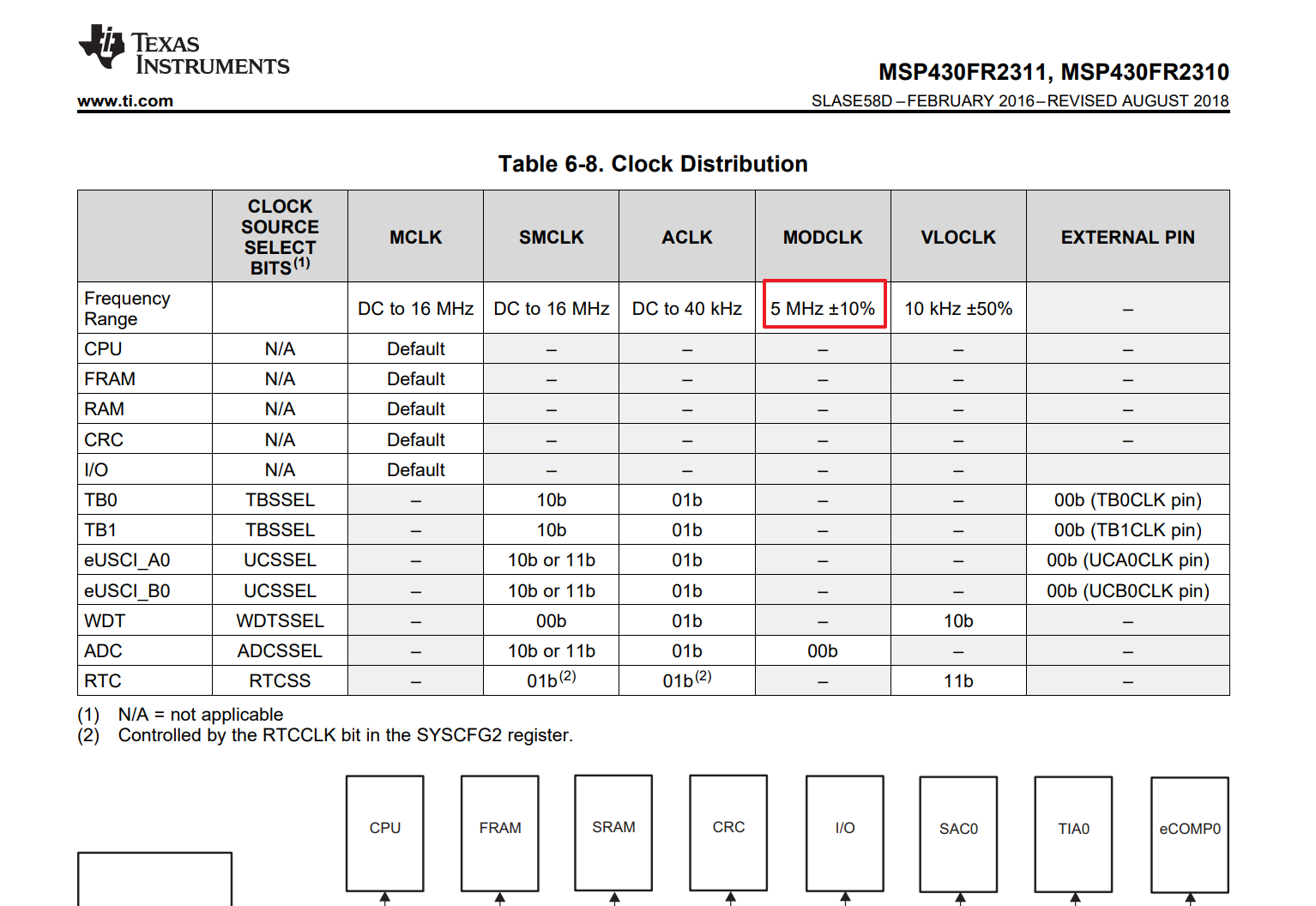
    By the way, the accuracy of MODCLK around ±10% :

    Best Regards

    Johnson

  • Hi Johnson,

    Thank you for your reply. MODCLK is not being used in this design.

    The program for MCLK would be useful except that only part of it is shown. What appeared ended with a "while" statement.

  • Hi Robert,

    This is only a example code, so this code just the setting of the clock.

    #include <msp430.h>
    
    int main(void)
    {
        WDTCTL = WDTPW | WDTHOLD;                          // Stop watchdog timer
    
        // Configure one FRAM waitstate as required by the device datasheet for MCLK
        // operation beyond 8MHz _before_ configuring the clock system.
        FRCTL0 = FRCTLPW | NWAITS_1;
    
        __bis_SR_register(SCG0);                           // disable FLL
        CSCTL3 |= SELREF__REFOCLK;                         // Set REFO as FLL reference source
        CSCTL0 = 0;                                        // clear DCO and MOD registers
        CSCTL1 &= ~(DCORSEL_7);                            // Clear DCO frequency select bits first
        CSCTL1 |= DCORSEL_5;                               // Set DCO = 16MHz
        CSCTL2 = FLLD_0 + 487;                             // DCOCLKDIV = 16MHz
        __delay_cycles(3);  
        __bic_SR_register(SCG0);                           // enable FLL
        while(CSCTL7 & (FLLUNLOCK0 | FLLUNLOCK1));         // FLL locked
        
        CSCTL4 = SELMS__DCOCLKDIV | SELA__REFOCLK;        // set default REFO(~32768Hz) as ACLK source, ACLK = 32768Hz
                                                           // default DCOCLKDIV as MCLK and SMCLK source
    
        P1DIR |= BIT0 | BIT1 | BIT2;                       // set ACLK SMCLK and LED pin as output
        P1SEL1 |= BIT0 | BIT1;                             // set ACLK and  SMCLK pin as second function
    
        PM5CTL0 &= ~LOCKLPM5;                              // Disable the GPIO power-on default high-impedance mode
                                                           // to activate previously configured port settings
    
        while(1)
        {
            P1OUT ^= BIT2;                                 // Toggle P1.2 using exclusive-OR
            __delay_cycles(8000000);                       // Delay for 8000000*(1/MCLK)=0.5s
        }
    }
    

    Best Regards

    Johnson

  • Hi Johnson,

    Thank you for the complete code. This looks like the manual way to set the clock. In reading the users manual, it appeared as though the clock set operation was mostly automatic, with only the desired frequency having to be set.

    By setting so many parameters, have I turned off the automatic set procedure? The automatic set procedure is what I want, as the user manual said it was best to stick with the factory trim.

    Please advise, and Thank you again,

    Robert.

  • Hi Rebort,

    What is your means about "automatic set procedure" ? Is waiting FLL locked?

     while(CSCTL7 & (FLLUNLOCK0 | FLLUNLOCK1));         // FLL locked

    Could you tell me why you wanna turned off this procedure? In order to saving start-up time?

    Best Regards

    Johnson

  • Hi Johnson,

    The users manual says the manual procedure is not the normal set procedure. Unless I am reading it wrong, the FLL should set itself automatically.

    Am I wrong here? Does the FLL need to be manually set up every time?

    Thank you for your time,

    Robert.

  • Hi Rebort,

    You just need setting some parameter (reference clock source, DCO frequency range, DCO target frequency) and FLL will locked this clock frequency automatically depend on your requirement, thus you can execute the normal program after waiting for the FLL lock.

    Best Regards

    Johnson

  • Hi Johnson,

    Thank you for your responses. I have figured this out with the help of your code example.

    In the future, the correct answer to my original question should have been,

    "Hello Robert,

    FLL lock is only automatic for the default setting of MCLK = 1Mhz.

    Any other setting of MCLK will require setting the FLL lock manually by using the paragraph 3.2.11.1 of the users manual. Here is a code example which follows paragraph 3.2.11.1.

    Let me know if you need further assistance."

**Attention** This is a public forum