This thread has been locked.

If you have a related question, please click the "Ask a related question" button in the top right corner. The newly created question will be automatically linked to this question.

CCS/MSP432P401R: Detecting Phase Delay of Two Signals Using GPIO and Timer

Part Number: MSP432P401R

Tool/software: Code Composer Studio

Hi 

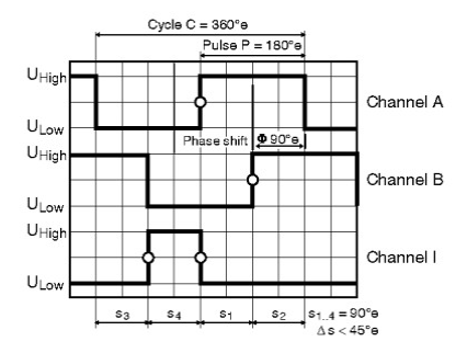
I have two signals, A and B, coming from an encoder (to measure the velocity of motor shaft). If the direction of the motor is clockwise, the signal A leads signal B and vise versa. I am going to detect this phase delay with MSP432P401R. To do so, I am using P2.6 and P2.7 as GPIO and activated the interrupt for them and connected the channel A and channel B to them. Also, I am using Timer_A0. I have created a function innthe while loop, and in this function, first, the timer is initiated, then two flags, flagA and flagB, are reset. The captures are store into two unsigned shorts, captureA and captureB. when two interrupts, one from channel A and one from channel B occurred, In the ISR, the TA0R are stored in the captureA, and captueB.

The mentioned variables then are compared and the direction is defined. I have written the code, but there is a problem, sometimes it  captureA is bigger and sometimes captureB in the same condition. Would you please help me resolve the issue? thanks!

The code is brought below:

#include "msp.h"
#include "math.h"

unsigned short captureA,captureB;//the timers values for signal A interrup and signal B is stored in them.
short int phase_detection,CW,flagA=0,flagB=0;
int o; float motor1_velocity(void) { captureA=0; captureB=0; // //Define the direction of rotation// phase_detection=1; TIMER_A0->CTL = TIMER_A_CTL_TASSEL_2 | //Select SMCLK as clock source for timer TIMER_A_CTL_ID_3 | //ID=8 TIMER_A_CTL_CLR; // clear TA0R TIMER_A0->CTL |= TIMER_A_CTL_MC_2 ; // Start timer in continuous mode P2IE |= BIT6 + BIT7; // The interrupt is activated for P2.6/P2.7. P2IES &= ~(BIT6 + BIT7); // The interrupt is activated on high to low transition. P2IFG &= ~(BIT6 + BIT7); // P2.6/P2.7 IFG cleared while (!((flagA&1)&(flagB&1))); //wait until two captures for channels A and B occure. phase_detection=0; //Now, we change our policy to frequency measurement. flagA=0; flagB=0; P2IE &= ~(BIT6 + BIT7); // The interrupts are temporarily halted to define the lead/lag of channel A wrt channel B. if ((captureA-captureB)>0){CW=0;} //The motor is rotating CW. else {CW=1;}// The motor is rotating CCW. return 0; } void main(void) { WDT_A->CTL = WDT_A_CTL_PW | WDT_A_CTL_HOLD; // stop watchdog timer //******Pin configurations**********// NVIC_ClearPendingIRQ(PORT2_IRQn); // Clear any stale Interrupt Controller status NVIC_EnableIRQ(PORT2_IRQn); // Enable P1 interrupt in the Interrupt Controller //****************************// P1DIR |=BIT0; P2DIR |= BIT1; P2REN |= BIT6 + BIT7; //Pullp/pulldown resistor is activated. P2DIR &= ~(BIT6+ BIT7); //P2.6/7 is defined as input pin. P2OUT &= ~ (BIT6 + BIT7); //The default of the P1.6/7 is low. __enable_irq(); while (1) { motor1_velocity(); for(o=650000;o>1;o--); } } /*Port 2 Interrupt handler*/ void PORT2_IRQHandler(void) { if(phase_detection==1) { if(P2IFG & BIT6) { captureA=TA0R; flagA=1; P1OUT ^=BIT0; P2IFG &=~ BIT6; } else if (P2IFG & BIT7) { captureB=TA0R; flagB=1; P2OUT ^= BIT1; P2IFG &=~ BIT7; } } }

  • Hi Saber,

    Saber Kazeminasab said:
    but there is a problem, sometimes it  captureA is bigger and sometimes captureB in the same condition.

    I think the reason is that timer is starting at an arbitrary time with respect to your two waveforms - Channel A, Channel B. Depending on when the Timer starts, either of the 2 channels could be larger. If you need a constant frame of reference, you need to make sure, the Timer starts on one particular channel's edge, for example, Channel A low to high edge. Then you can get the 2 values for Channel A & B as you are doing. If Channel B value is higher than Channel A, it is CW and if Channel B value is lower, it is CCW.

    Srinivas

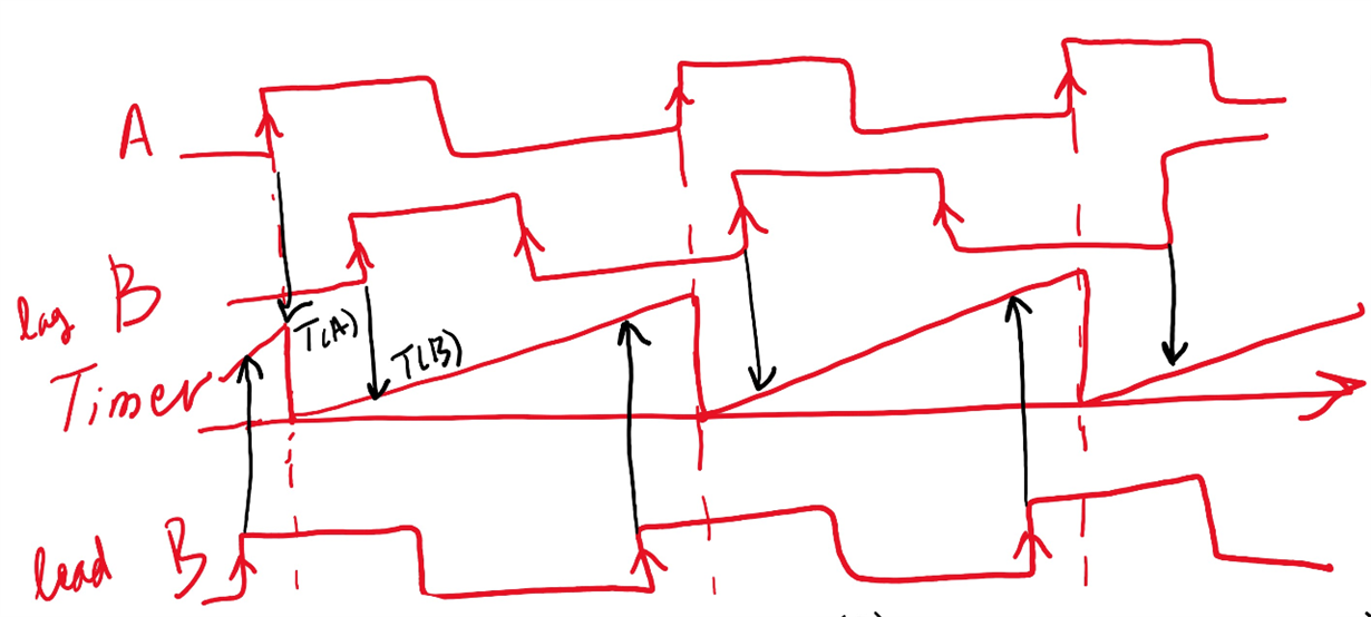
  • Thanks, Srinivas for your response. based on your suggestion, I drew a schematic for this

    Is that correct? But here, the frequency is also unknown and the next step after defining the direction is the frequency measurement. In other words, in this case, in two scenarios, B leads or lag A, the captureB value is more than captureA. How do you think we can compare them together? thanks!

    Saber

  • Hi Saber,

    That timing diagram does look correct.

    Saber Kazeminasab said:
    How do you think we can compare them together?

    As you point out, I think you will also need the period for A. You will need that to obtain the amount of B lead A scenario.

    Srinivas

  • I followed another scenario. I set two flags, flagA and flagB and removed the need for timer. Upon function call, a while loop waits until one of the mentioned flags are set. In the ISR, when an interrupt occurs, one of the flags is set, either flagA or flagB and the while loop is released. if the flagA=1, this means the channel A leads channel B, otherwise channel B. This technique has an error. To mitigate its error, I repeat for 5 times and based on "majority vote", define the direction of rotation.

    float motor1_velocity(void)
    {
             flagA=0;
             flagB=0;
             //Define the direction of rotation//
             phase_detection=1;
             P2IE |= BIT6 + BIT7;                     // The interrupt is activated for P2.6/P2.7.
             P2IES &= ~(BIT6 + BIT7);                     // The interrupt is activated on low to high transition.
             P2IFG &= ~(BIT6 + BIT7);                 // P2.6/P2.7 IFG cleared
             for (i=0;i<10;i++)
             {
             P2IE |= (BIT6 + BIT7);
             while (!((flagA&1)||(flagB&1)));          //wait until two captures for channels A and B occure.
             if (flagA==1 && flagB==0){CW[i]=0;}  //The motor is rotating CW.
             else if(flagB==1 && flagA==0) {CW[i]=1;}// The motor is rotating CCW.
             flagA=0;
             flagB=0;
             P2IE &= ~(BIT6 + BIT7);
             sum_direction += CW[i];
             }
             if (sum_direction>5){direction=1;}
             else {direction=0;}
             P2IE |= BIT6 + BIT7;
             sum_direction=0;
    }
    /*Port 2 Interrupt handler*/
    void PORT2_IRQHandler(void)
    {
    if(phase_detection==1)
    {
    if(P2IFG & BIT6)
    {
    //captureA=TA0R;
    flagA=1;
    P1OUT ^=BIT0;
    //P2IE &= ~(BIT6 + BIT7);                     // The interrupts are temporarily halted to define the lead/lag of channel A wrt channel B.
    P2IFG &=~ BIT6;
    }
    else if (P2IFG & BIT7)
    {
    //captureB=TA0R;
    flagB=1;
    P2OUT ^= BIT1;
    //P2IE &= ~(BIT6 + BIT7);                     // The interrupts are temporarily halted to define the lead/lag of channel A wrt channel B.
    P2IFG &=~ BIT7;
    }
    }

**Attention** This is a public forum