This thread has been locked.

If you have a related question, please click the "Ask a related question" button in the top right corner. The newly created question will be automatically linked to this question.

CCS/MSP430I2041: SBW does not work when connected through MSP-ISO

Part Number: MSP430I2041
Other Parts Discussed in Thread: MSP-EXP430F5529LP, EVM430-I2040S, MSP-ISO, MSP430F5529, MSP430FR2355, MSP430I2040, MSP-EXP430FR2355, MSP-EXP430G2ET

Tool/software: Code Composer Studio

Programmer : eZ-FET Lite from the MSP-EXP430F5529LP launchPad board

Target board : EVM430-I2040S

Software : CCS

With the above setup I was able to program the EVM430-I2040S through CCS with no problem.

I then try to connect the eZ-FET Lite to the MSP-ISO and then to the EVM430-I2040S and it does not work. the target is not recognized.

I see an identical issue reported here... but it was not resolved.

https://e2e.ti.com/support/microcontrollers/msp430/f/166/p/795398/2950132?tisearch=e2e-sitesearch&keymatch=sbw%252520isolation#2950132

My question:

I know the eZ-FET Lite SBW mode can run on 200khz, 400Khz and 600Khz clock based on what I read in 

http://www.ti.com/lit/ug/slau647n/slau647n.pdf?ts=1591179102850

My question is how can I select this clock frequency? I would like to set it to a lower frequency to test if it works through the MSP-ISO board.

  • Hey Linus,

    I disscuss how to change the speed settings in this E2E post, but you have to open your Target Configuration file in your CCS project (Might be in it's own folder) and go to the advanced tab.  There is Fast, Medium, and slow settings.  

    Also, I would double check the wiring connections.  Looking at the schematic, It looks like it would be very easy to use the wrong side of the J2 Header to connect the ISO_ signals to the target.  

    I've never used with MSP-ISO but I just ordered one.  It will take several days to come in, but hopefully we figure this out before then.  

    Thanks,

    JD

  • Hi JD,

    thanks for your response. I did manage to change the speed from medium to slow. 

    However, SBW is still not working over MSP-ISO for me.

    Are you aware if this setup is even possible or supported?

    Linus

  • Hey Linus,

    Yes, it definitely should be supported.  MSP-ISO is designed to plug onto launchpads which use SBW programming, so that should not be the issue.  I just checked and the EZ-FET-Lite does support MSP043I2xx devices.  We may be adding additional capacitance or noise by using a cables to connect it but as long as it is wired correctly, I believe it should work.  

    Based on your original post, if you remove the MSP-ISO and connect the EVM directly to the EZ-FET it programs fine.  Is that still correct?  If so, then we can assume we are using the correct programming connections on the EVM.  

    Can we test the MSP-ISO board with the MSP430F5529 on the launchpad?  If you place jumpers on J2 on the MSP-ISO board, you should be able to program MSP430F5529 examples to the launchpad via the ISO board to confirm that it is working.  You can choose any demo or example software from dev.ti.com here: http://dev.ti.com/tirex/explore/node?node=AFGe9w6ArCvklGHxSiZHUQ__IOGqZri__LATEST 

    Thanks,

    JD 

  • Hey Linus,

    I just received my MSP-ISO board.  I was able to plug it directly onto a MSP430FR2355 Launchpad that I have and then connect it to a MSP430I2040 in a socket breakout board and was able to program and debug over SBW.

    I just grabbed an MSP-EXP430F5529LP and I notice that it's programming head is larger.  The MSP-ISO does not just plug directly onto it. I have to wire the F5529  LP to the MSP-ISO board and then wire that to the MSP430I2040.  I'm going to try it real quick on my side and I'll let you know if I get it working. 

    Thanks,

    JD    

  • Okay, I was able to get the MSP-ISO working with the MSP430F5529 Launchpad, but I did run into one issue.  The MSP-ISO board requires the 5V also be connected, in addition to 3.3V, GND, SBWTCK, and SBWTDIO.

    Once I connect 5V, I was able to see that I was getting power on my target board.  Then I connected the SBW signals and programmed at the default, medium speed.  I probably have about 12 inches of cable total, which is longer than ideal but is working on my setup. 

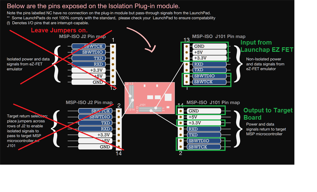
    I also had to be very careful to pay attention to the orientation of the ISO board/Headers.  The easiest way I found to connect it with the MSP-EXP430F5529LP was to leave the jumpers on the MSP-ISO board and just connect only through J1.  Input signals on one side and output Isolated signals on the other.  Like this:

     It was much simpler to use the MSP-ISO with a cheap launchpad that allows you to plug the MSP-ISO directly on and then pull the Isolated signals from J2.  Something like MSP-EXP430G2ET or MSP-EXP430FR2355

    Thanks,

    JD

  • Hi JD,

    Thanks so much for trying out the circuits. 

    1. Yes, without MSP-ISO and connecting MSP-EXP430F5529LP (SBW) directly to EVM430-I2040S and it works fine.

    2. Based on your last post, it is equivalent to what I did. I shorted JP101 and jumper from J2. What I also did differently is I removed J3 and powered 3.3V by jumper wire on both sides.

    Nevertheless, I used your method and tried it out. Again, I am getting "Unknown Device" error on CCS.

    I noticed you used the breakout board while I am using the EVM430-I2040S. Perhaps there is some incompatibility there. 

    If you have the EVM430-I2040S to test out, it would be great. I had to use the EVM430-I2040S as our product is based on this design. In fact now I am worried our board may not work with MSP-ISO when it comes back.

    I'll spend some time to scope the signals and see if I can spot anything.

  • Hey Linus,

    I don't have an EVM430-I2040s handy right now, but looking at the schematic I don't see any reason that MSP-ISO shouldn't work, especially if SBW is workings non-isolated.  

    What do you mean by "I shorted JP101 and Jumper from J2"?  

    Are you applying 5V to the MSP-ISO board from the launchpad?  

    I'll see if I can get my hands on an EVM430-I2040s next week just to have the exact same setup.  

    Thanks,

    JD

  • Hi JD,

    What do you mean by "I shorted JP101 and Jumper from J2"?  

    > I mean I shorted the odd and even pins on JP101. I then make use of J2 to jump wires to the EX FET and the EVM.

    > What you did is short the odd/even pins on J2 and use JP101 for connections.

    Are you applying 5V to the MSP-ISO board from the launchpad?  

    > Yes. My last test was using the exact same setup as you.

  • Linus,

    You definitely should not short J101 pins.  By shorting these pins, I'm not sure how the board will perform but you are bypassing all ISO protection on the board.  

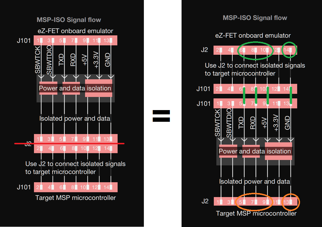
    The Odd pins, 1-13 are the inputs to the ISO board.  The signals then are passed through isolation, then through J2, and finally output on J101 EVEN pins, 2-4.  You can pull the isolated signals either off J2, or you can short J2 with the provided jumpers and pull the Isolated signals from J101 EVEN pins.     

    This is shown in the Quick Start guide that ships in the box with MSP-ISO. (shown below)

    I don't know if wiring the board in this way would damage the components or not, but you may have to replace your MSP-ISO.  

    Thanks,

    JD


  • Hi JD,

    Some points to high lisght below....

    1. I did not power or connect the AC. I was planning to get MSP-ISO to work properly first before I turn on AC. So, I was powering the EVM using the external 3.3V. I don't think the MSP-ISO would be damanged. 

    2. I followed the instructions here.... actually, it is not much difference from your method. Please correct me if I missed out something.

    http://software-dl.ti.com/msp430/msp430_public_sw/mcu/msp430/EnergyMeasurementDesignCenter/1_30_00_00/release/EnergyMeasurementDesignCenter_1_30_00_00/docs/users_guide/html/Energy_Measurement_Technology_Guide_html/markdown/ch_designcenter.html#make-the-hardware-connections

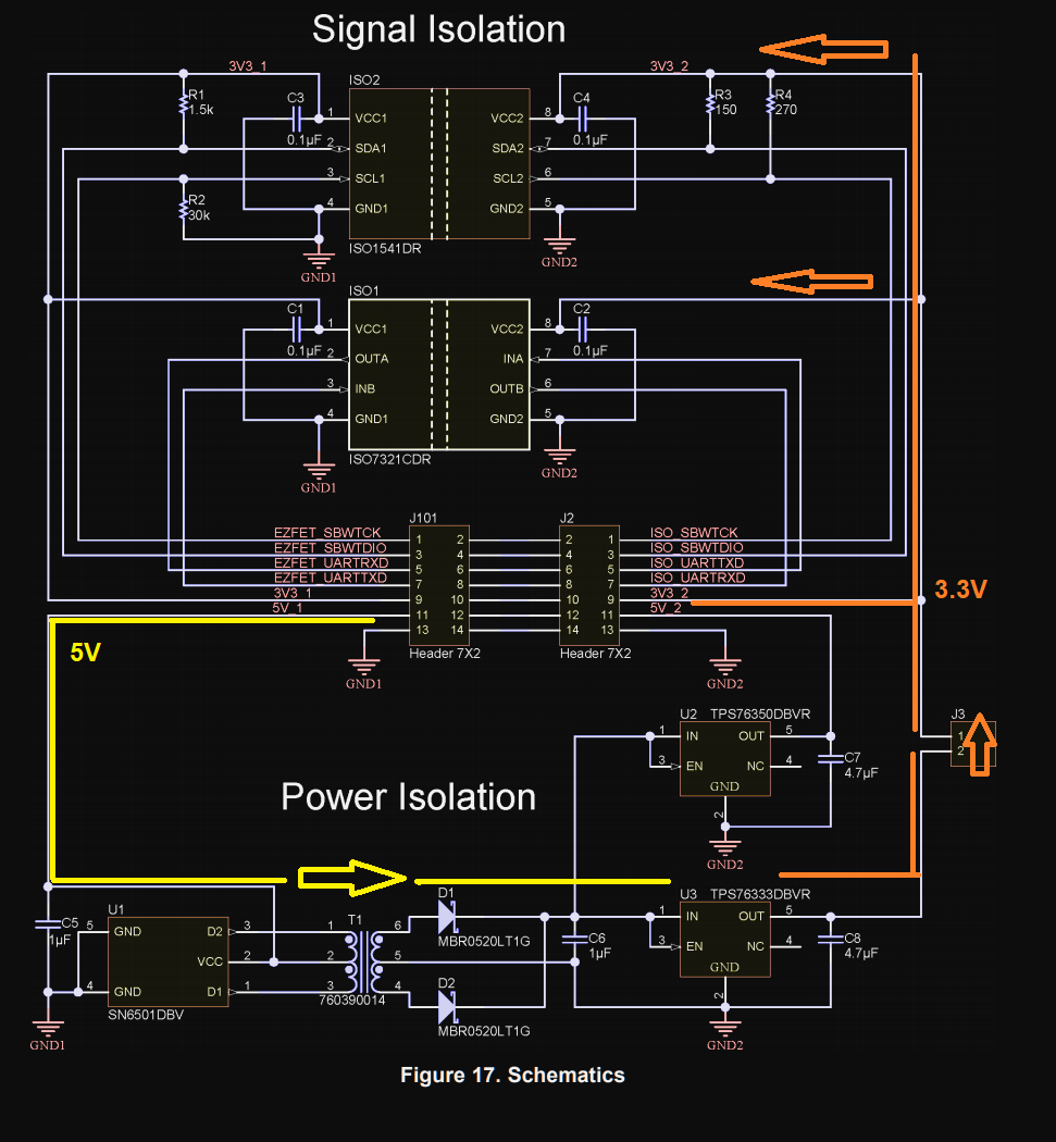
    3. This is my connections. The scematic is from the MSP-ISO datasheet. Do note that J3 is NOT connected and 5V is NOT connected. In this case you may point out that the power supply is not isolated. The reason I did this is because I didn't want the 3.3V to come from the AC/DC converter on the EVM. 

    4. I followed your connection recommendation from earlier post and capture on the logic analyzer and realized that there are activity on the SBW. I don't know the protocol enough to know what went wrong.

    Figure 1-1 : Without MSP-ISO

    Figgure 1-2 : Without MSP-ISP (zoom in on first part)

    Figure 2-1 : WITH MSP-ISO

    Figure 2-2 With MSP-ISO (Zoom in on first part)

  • Hey Linus,

    I have to apologize and I don't think you've damaged the board.  It looks like you are correct and thanks for linking me to the design guide.  At first glance, I even thought the guide was wrong but I see now that they are using the circular design of the board to short J1 and use J2 for input and output.  This is the opposite of what I did.  (I'm not sure why it's written this way as I feel it's more difficult/more "wires" than using the included J2 Jumpers.  I'll send the team feedback.)    

    I mocked this up in Paint to explain what they had recommended.    

    Also, Unfortunately, our images didn't come through.  E2E seems to struggle if your just past in images, I have to save my capture then upload them to get them to show. Can you re-send share them, mainly your connections?  If you are not using J3, are you providing 3.3V to the EVM when you are programming?       

    As for looking at the SBW signals, trying to decode the protocol usually is much more trouble than it's worth. We typically are just looking first for basic activity and then clear issues such as high noise or poor signals.

    Sorry again for the confusion.  I did order the EVM and it should be here early next week.  I'll also test your connections with the breakout board once I understand your power setup. 

    Thanks,

    JD  

  • Hi JD,

    I reposted with the images uploaded properly... I hope.

    Some additional points.

    - I actually think your method is cleaner and easier to connect. I will stick to that.

    - All 3.3V comes from the MSP-EXP430F5529LP. It powers both side of the MSP-ISP as well as the EVM. The same goes for GND. Again this is for testing. When I am ready to debug with AC on, I will power the EVM from AC and power the ISO side from the EVM. 

    Some points to high light below....

    1. I did not power or connect the AC. I was planning to get MSP-ISO to work properly first before I turn on AC. So, I was powering the EVM using the external 3.3V. I don't think the MSP-ISO would be damanged. 

    2. I followed the instructions here.... actually, it is not much difference from your method. Please correct me if I missed out something.

    http://software-dl.ti.com/msp430/msp430_public_sw/mcu/msp430/EnergyMeasurementDesignCenter/1_30_00_00/release/EnergyMeasurementDesignCenter_1_30_00_00/docs/users_guide/html/Energy_Measurement_Technology_Guide_html/markdown/ch_designcenter.html#make-the-hardware-connections

    3. This is my connections. The schematic is from the MSP-ISO datasheet. Do note that J3 is NOT connected and 5V is NOT connected. In this case you may point out that the power supply is not isolated. The reason I did this is because I didn't want the 3.3V to come from the AC/DC converter on the EVM. 

    4. I followed your connection recommendation from earlier post and capture on the logic analyzer and realized that there are activity on the SBW. I don't know the protocol enough to know what went wrong.

    Figure 1-1 : Without MSP-ISO

    Figgure 1-2 : Without MSP-ISP (zoom in on first part)

    Figure 2-1 : WITH MSP-ISO

    Figure 2-2 With MSP-ISO (Zoom in on first part)

  • Hey Linus,

    I can see the images now and understand mostly how you had it hooked up.  I'm still confused on your power configuration:  

    > "All 3.3V comes from the MSP-EXP430F5529LP. It powers both sides of the MSP-ISO"   

    and 

    > "I was powering the EVM using the external 3.3V."

    Have you checked that you are getting 3.3V on the target board? 

    If you are using an external 3.3V supply for the Target Board, then I think your configuration is fine and J3 can be disconnected.   But, if you are trying to source Isolated 3.3V from the MSP-ISO board, then I believe you need to connect 5V from the launchpad and replace J3.  Then  MSP-ISO should be able to supply your target MSP430I2040.  

    I'm using this later configuration of having 3.3V supplied from MSP-ISO.  Looking at the schematic, the 5V input rail is actually required in my case as it is actually what is sourcing 3.3V on the isolated side. 


    Thanks,

    JD

  • Hi JD,

    Hopefully, this diagram would clarify how I connect the power. Once again, this is for testing the ISO logic, I understand the power are not isolated.

    Going forward with this test, I am going to use your original recommendation to make use of the 5V. That method is cleaner and easier to implement. I also would like to confirm that I had tested that method and it is giving me same results.

    Linus

  • Hey Linus,

    Get it working yet?  

    I got notified that the EVM has shipped and should arrive in the next few days.  

    Thanks,

    JD

  • Hi JD,

    unfortunately no. Right now I would power off AC and program the EVM without MSP-ISO.

    I hope to hear some good news from you once you get your board.

    Best regards,

    Linus

  • Hi JD,

    today I took another shot and I believed I found the problem.

    The problem is in the SBW_TDIO pin and I believe it comprises of 2 issues.

    First, let's look at the waveform. The blue waveform is TDIO. When I saw this I believe it could be due to the 2.2nF capacitor on the TDIO pin on the EVM. According to the following document, the range of this capacitor is between 0.1nF to 2.2nF. 

    https://www.ti.com/lit/ug/slau278af/slau278af.pdf?ts=1591945266355

    I didn't have a 0.1nF so I figured with the number of jumper wires I could simply remove the capacitor to try. And it works. I was able to get SBW to work over CCS with the MSP-ISO in between.

    But when I look at the waveform closely, it seems like the TDIO is not driven down to GND. So I think the second problem is the pullup resistors and the drive strength of the ISO1541DR on the MSP-ISO board. 

    I may have to increase the pull up resistance on the MSP-ISO a little. 

  • Hey Kerk,

    Good to hear that you got it working!  

    I received my EVM430-I2040S on Friday but didn't have a chance to test with it until last night.  I'm seeing exactly what you are.  I'm unable to program the board through MSP-ISO currently and see the same issues on the SBW_TDIO signal.  I agree, that somehow the problem seems to be related to the RC components on the line.  

    Here are my captures showing signals as analog and digital:

    SBW working without the MSP-ISO:

    SBW with MSP-ISO on the EVM430-I2040S:

    Thanks,

    JD

  • Hi JD,

    thanks for confirming my observations.

    I am going a little off-topic here. Because you now have the exact same setup as me, I was wondering if you could help me try out and see if you encounter the same issue I posted here.

    https://e2e.ti.com/support/microcontrollers/msp430/f/166/p/914835/3380157#3380157

    You don't need MSP-ISO to replicate this. After downloading code, and when I enter debug mode, it takes 5 minutes to get to "main". This is with the SBW running at medium speed.

    Linus

**Attention** This is a public forum