This thread has been locked.

If you have a related question, please click the "Ask a related question" button in the top right corner. The newly created question will be automatically linked to this question.

CCS/MSP430FR6989: MSP430FR6989

Part Number: MSP430FR6989
Other Parts Discussed in Thread: RM48L952

Tool/software: Code Composer Studio

Dear Sir,

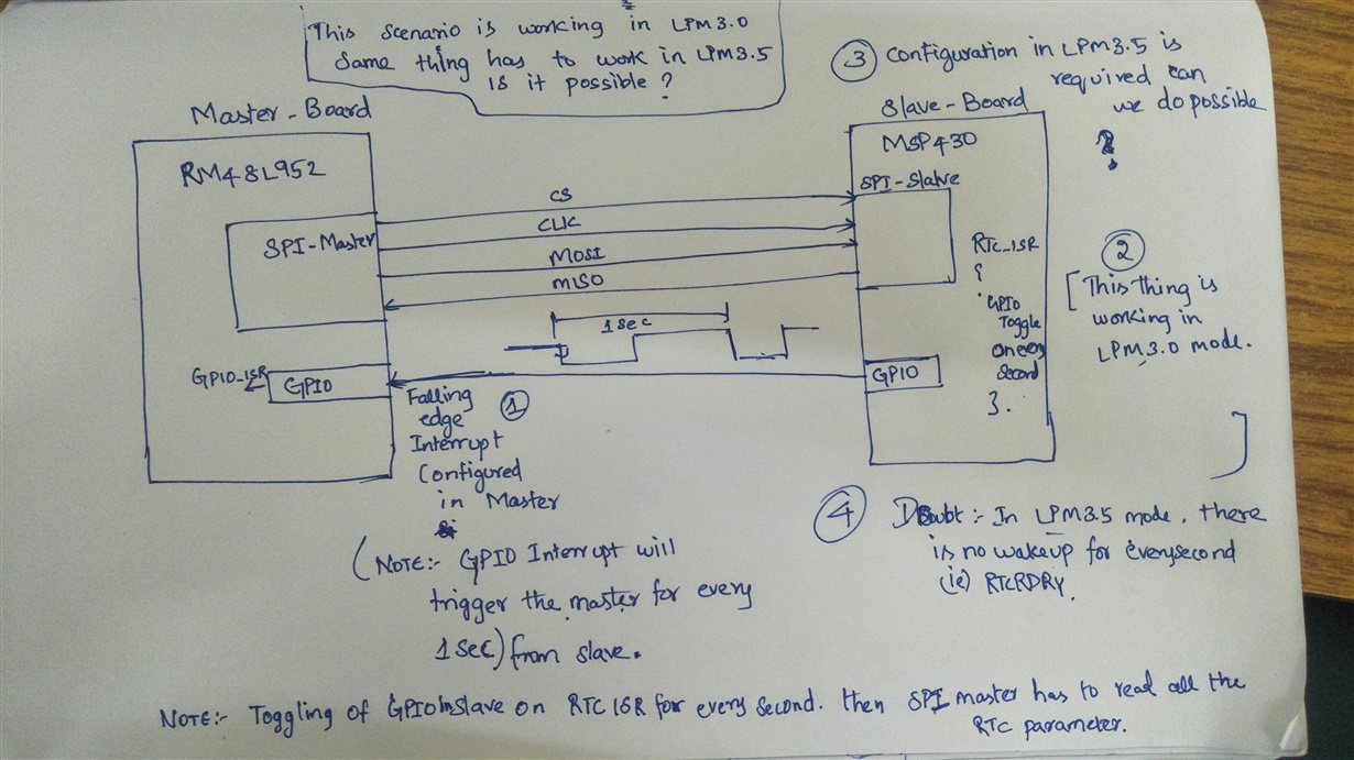
I have two boards, one is Master board (RM48L952) and one more is slave board (MSP430).

In your project  main agenda is to read the RTC value from the Slave board to Master board through SPI communication for every second on RTC_READY interrupt. I have to configure master board SPI as Master and Slave board as SPI Slave.

I have to configure RTC_C Module as LPM3.5 then , read the RTC value from the Slave board to Master board through SPI communication for every second on RTC_READY interrupt is it possible?

Can you please help me.

Regards,

Anand Kumar N S

  • Hello Anand,

    In SPI communication all actions are initialized by the SPI-master. You can define a protocol to let the 'L952-master request the RTC-values piece by piece; the '430-slave would answer piece by piece then.

    Now, you would like this to happen exactly every second. The exact time information however is known to the '430-slave, not the 'L952-master. Here the '430-slave could notify the '952-master via a separate wire when that 1sec event fired. Then the 'L952 could pick up the other values of the RTC. If you have no other SPI-members ot those lines you could even re-program the port functions and reuse the signal lined between slave and master.

    I saw that the 'L952 device is meant for safety critical applications. If your application is of that kind I would propose to use a bi-directional serial port communication instead.

    - The '430 can simply start the communication whenever a second gets completed, You would only need 2 signal lines.

    - The single byte transmission always terminates. (whereas on SPI a loss of a clock-cycle a SPI reset may be required. Even if this is a rare event you wouldneed to consider it as failure case in safety) .

    - Both devices can communicate on top of the time-message some kind of "life pulse" message. On timeout, or if one side does not acknowledge anymore the controller that is still alive can restart the other, or at least start an alert or so.

    And back to the basic answer: Yes 430 devices can be used for your task, but not exactly as you described. Usually the master would start the request.

    have a nice day

         Johann

  • Hi johann,

    Thanks for early reply. 

    Once again thanks for your suggestion, i will discuss regarding to hardware team.

    i want to clarify few thing, i have attached pic in that, mentioned detailed process flow,

    i want to do the same thing in Low power Mode 3.5 (LPM3.5) can i do that? Is it possible???

    But the same thing is working fine in LPM3.0. But we want to do the same process in LPM3.5.

    Process flow steps,

    1. In Slave MSP430, RTC_C module is configured with RTCRDRY interrupt, so i will get RTC_ISR forevery second in that i am making GPIO Low and High.
    2. So, the Master RM48L952 , get interrupt and inside the interrupt i am doing SPI transaction to read the RTC parameter.   Note: In master , GPIO pin is configured for GPIO falling edge interrupt. 
    3. Above flow is working fine in LPM3.0 , but we required the same to work in LPM3.5 mode.

    Kindly guide me to solve this problem.

    Thank you,

    Have a nice day.

    AnandKumar

  • Hello again AnandKumar,

    Yes I'm sure it works in LPM3.5. Some time ago I played with the RTC_C. I have not used RTCRDY interrupt, but I used the pre-scaler interrupts RT1PSIFG and RT0PSIFG in LPM3.5, and those made it.. There is a slight difference even though the signal is coming from the same source on mux-select "110" .    RTCRDY will trigger a little after the complete second; RT1PSIFG will trigger exactly at  500ms after a full second. On mux-select "101" the interrupts are triggered 250ms after the full second and 750ms after the full second.  Therefore no worries for rippling of the counter stage either.

    have fun

       Johann

  • Hello Johann,

    Thanks for your suggestion.

    I have configured RTCPS1IT for 1 second, It was fine for reading rtc value to the master board for every second on wakeup from LPM3.5 through SPI transaction and enter it again to LPM3.5.

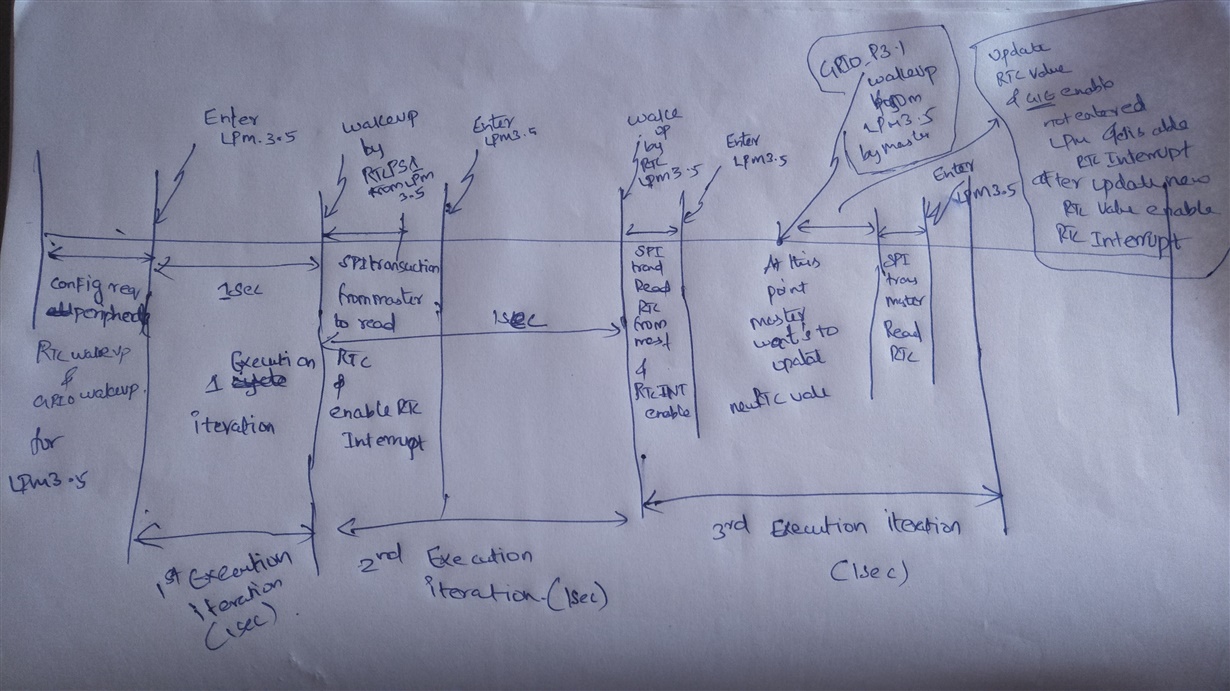
    Here, I'm facing one more problem that, I want to update the new RTC value from the Master board through SPI Transaction to MSP430 which i have configured for LPM3.5, And i configured  two wakeup source

    one is  RTCPS1 -Wakeup source for every second to send RTC value to master and  one more is GPIO P3.1  wakeup source from LPM3.5 to update a new rtc value from master to MSP430 board.

    Program flow which i was working on,

    1. For every second RTCPS1 wakeup will happen and RTC value will send to master through SPI transaction. a nd enter it again into LPM3.5

    2. When i want to Update a new RTC value, Master board  will send GPIO wakeup for MSP430 to comeout from LPM3.5. and before updating disabling the RTC wakeup source and update the new rtc value to the            RTC  register. After updating the new rtc value , enabling the RTC wakeup source and entering again into LPM3.5.

    3. if i tried to read the RTC value from MSP430, on very first time it was reading the Update rtc  value and later on read the old rtc value.(Here i am facing the problem)

    Could you please help me to solve this problem johann..

    Here , I have some doubt's 

    1. Can we enable RTC & GPIO as wakeup source for LPM3.5?

    2. When MSP430 enters into LPM3.5 and Configured for RTC_WAKEUP and GPIO_WAKEUP. Instead of wakingup by RTC, wakeup happens by GPIO then, RTC wakeup source will get cleared or it retained?

    Here i have attached my code for ur reference,

    68864.main.c
    /*
     --COPYRIGHT--,BSD_EX
     * Copyright (c) 2014, Texas Instruments Incorporated
     * All rights reserved.
     *
     * Redistribution and use in source and binary forms, with or without
     * modification, are permitted provided that the following conditions
     * are met:
     *
     * *  Redistributions of source code must retain the above copyright
     *    notice, this list of conditions and the following disclaimer.
     *
     * *  Redistributions in binary form must reproduce the above copyright
     *    notice, this list of conditions and the following disclaimer in the
     *    documentation and/or other materials provided with the distribution.
     *
     * *  Neither the name of Texas Instruments Incorporated nor the names of
     *    its contributors may be used to endorse or promote products derived
     *    from this software without specific prior written permission.
     *
     * THIS SOFTWARE IS PROVIDED BY THE COPYRIGHT HOLDERS AND CONTRIBUTORS "AS IS"
     * AND ANY EXPRESS OR IMPLIED WARRANTIES, INCLUDING, BUT NOT LIMITED TO,
     * THE IMPLIED WARRANTIES OF MERCHANTABILITY AND FITNESS FOR A PARTICULAR
     * PURPOSE ARE DISCLAIMED. IN NO EVENT SHALL THE COPYRIGHT OWNER OR
     * CONTRIBUTORS BE LIABLE FOR ANY DIRECT, INDIRECT, INCIDENTAL, SPECIAL,
     * EXEMPLARY, OR CONSEQUENTIAL DAMAGES (INCLUDING, BUT NOT LIMITED TO,
     * PROCUREMENT OF SUBSTITUTE GOODS OR SERVICES; LOSS OF USE, DATA, OR PROFITS;
     * OR BUSINESS INTERRUPTION) HOWEVER CAUSED AND ON ANY THEORY OF LIABILITY,
     * WHETHER IN CONTRACT, STRICT LIABILITY, OR TORT (INCLUDING NEGLIGENCE OR
     * OTHERWISE) ARISING IN ANY WAY OUT OF THE USE OF THIS SOFTWARE,
     * EVEN IF ADVISED OF THE POSSIBILITY OF SUCH DAMAGE.
     *
     *******************************************************************************
     *
     *                       MSP430 CODE EXAMPLE DISCLAIMER
     *
     * MSP430 code examples are self-contained low-level programs that typically
     * demonstrate a single peripheral function or device feature in a highly
     * concise manner. For this the code may rely on the device's power-on default
     * register values and settings such as the clock configuration and care must
     * be taken when combining code from several examples to avoid potential side
     * effects. Also see www.ti.com/grace for a GUI- and www.ti.com/msp430ware
     * for an API functional library-approach to peripheral configuration.
     *
     * --/COPYRIGHT--
    ******************************************************************************
    //   MSP430F59xx Demo - eUSCI_A0, SPI 4-Wire Slave Data Echo
    //
    //   Description: SPI slave talks to SPI master using 4-wire mode. Data received
    //   from master is echoed back.
    //   ACLK = 32.768kHz, MCLK = SMCLK = DCO ~ 1MHz
    //   Note: Ensure slave is powered up before master to prevent delays due to
    //   slave init.
    //
    //
    //                   MSP430FR6989
    //                 -----------------
    //            /|\ |              XIN|-
    //             |  |                 | 32KHz Crystal
    //             ---|RST          XOUT|-
    //                |                 |
    //                |             P2.0|-> Data Out (UCA0SOMI)
    //                |                 |
    //                |             P2.1|<- Data In (UCA0SIMO)
    //                |                 |
    //                |             P1.5|-> Serial Clock Out (UCA0CLK)
    //                |             P1.4|<- Slave Select (UCA0STE)
    //
    //
    //   William Goh
    //   Texas Instruments Inc.
    //   April 2014
    //   Built with IAR Embedded Workbench V5.60 & Code Composer Studio V6.0
    ****************************************************************************/


    /*
     * Clock sources default Configuration after reset
     * ==========================================================================================================
     * 1) SMCLK    : Subsystem master clock is ON
     * 2) VLO      : Internal very-low-power low-frequency oscillator is OFF
     * 3) LFXTCLK  : Low-frequency oscillator is OFF
     *    3.1) LFXT bypass : LFXT sourced from external crystal (RESET)
     *    3.2) LFXTDRIVE   : Maximum drive strength and maximum current consumption LFXT oscillator(3h)
     * 4) HFXTCLK  : High-frequency oscillator is OFF
     * 5) DCOCLK   : Internal digitally controlled oscillator (DCO) is ON (DCO clock is by default 4 MHz).
     * 6) MODCLK   : Internal low-power oscillator with 5-MHz typical frequency
     * ===========================================================================================================
     */


    #include "main.h"
    #include "Peripheral_Init.h"
    
    
    //#define DEBUGPORT_UART
    
    
    volatile uint8_t Rxdata=0;
    RTC_t Calender_Time;
    
    uint8_t RTCUpdateFlag=0;
    void SendRTCData(void);
    volatile uint8_t UartRXData = 0;
    volatile uint8_t UartTXData = 1;
    volatile uint8_t RTC_Counter=0;
    
    extern uint8_t MinFlagCmplt;
    extern uint8_t Trackflow;
    
    
    int main(void)
    {
        int i=0;
        // Stop WatchDog Timer
        WDTCTL = WDTPW | WDTHOLD;
    
        // Determine whether we are coming out of an LPMx.5 or a regular RESET.
        if (SYSRSTIV == SYSRSTIV_LPM5WU)
        {
            // When woken up from LPM3.5, reinit
            WakeUpLPM35(WAKEUPSOURCE_RTC);           // LPMx.5 wakeup specific init code
            __bis_SR_register(GIE);
            //__enable_interrupt();                   // The RTC interrupt should trigger now...
           // while (1);                              // Forever loop after returning from RTC ISR.
        }
        else
        {
            //Configure PinMux
            PinMux();
    
            // Disable the GPIO power-on default high-impedance mode to activate
            // previously configured port settings
            PM5CTL0 &= ~LOCKLPM5;
    
            // Configure the System Clock
            SystemClockConfig();
    
            //Configure the RTC parameter
            Calender_Time.Sec  = 02;
            Calender_Time.Min  = 58;
            Calender_Time.Hour = 23;
            Calender_Time.Day_of_week = 02;
            Calender_Time.Day  = 18;
            Calender_Time.Month = 06;
            Calender_Time.Year = 2020;
    
            //Initilaize the MSP430 Peripherals
            MSP430_PeripheralInit(RST_NOTBY_WAKEUP_SIGNAL,WAKEUPSOURCE_RST);
    
    
            // SET the P4.0 to Default High state,
            // Once P4.0 is Low ,generate interrupt to master to start fetching RTC value
            // P4.0 low to high transaction will happen inside RTC ISR
            P4OUT = 0x01;
    
            // By default, RTC_UpdateCmplt will be cleared
            Calender_Time.RTC_UpdateCmplt=RESET;
    
    
            // Enter LPM3 mode w/ interrupts enabled
           // __bis_SR_register(LPM3_bits| GIE);
            // This function will NOT return.
            EnterLPM35();
        }
    
        while(1)
        {
            if(Calender_Time.RTC_UpdateCmplt==SET)
            {
                // Re-init with New RTC value
                RTC_Initialisation(&Calender_Time,RST_NOTBY_WAKEUP_SIGNAL);
                RTCCTL0_H=RTC_UNLOCK;
                // The calendar is stopped as well as the Pre-scaler counters, RT0PS and RT1PS
                RTCCTL1 |= RTCHOLD;
                RTCPS1CTL |=   RTCPRESCALAR1_INTERVALTIME_1S | RTCPRESCALAR1_INTERRUPTENABLE;//(7<<11)|
                //Real-time clock (calendar mode) is operational.(Release the RTC)
                RTCCTL1 &= ~RTCHOLD;
    
    
                // Reset the RTC update completion flag after update.
                Calender_Time.RTC_UpdateCmplt=RESET;
    
                Trackflow=Trackflow;
                for(i=0;i<65535;i++);
                // Enter LPM3 mode w/ interrupts enabled
                __bis_SR_register(LPM3_bits | GIE);
                //EnterLPM35();
            }
    
            if(Calender_Time.RTC_TranmitCmplt==1)
            {
                // Enter LPM3 mode w/ interrupts enabled
                EnterLPM35();
    
                //This is the redundant code it wont execute below statement CPU goes to LMP3.5
                //But as Per software standard made the below statement
                Calender_Time.RTC_TranmitCmplt=0;
            }
        }
    
    #ifdef DEBUGPORT_UART
          while(1)
          {
              while(!(UCA1IFG & UCTXIFG));
                 UCA1TXBUF = UartTXData;                     // Load data onto buffer
              /*while(!(UCA1IFG & UCRXIFG));
                  UartRXData = UCA1RXBUF;                       // Load data onto buffer
                  UartTXData++;*/
    
              __bis_SR_register(LPM3_bits| GIE);                    // Enter LPM3 mode w/ interrupts enabled
          }
    #endif
    }
    
    
    /*------------------------------------------------------------------------------------------------
    FUNCTION NAME: SendRTCValuetoMaster()
    DESCRIPTION  : Send the Update RTC value to Master Board
    PARAMETERS   : command is of type uint8_t
    RETURN       : None
    --------------------------------------------------------------------------------------------------*/
    inline void SendRTCValuetoMaster(uint8_t u8Command)
    {
        switch(u8Command)
         {
             case CMD_SEC:
                     Rxdata=Calender_Time.Min;
                     UCA0TXBUF=Rxdata;// In RTC_ISR Txbuf is loaded with RTCSEC;Load next byte as min
                     break;
             case CMD_MIN:
                     Rxdata= Calender_Time.Hour;
                     UCA0TXBUF=Rxdata; // Tx would have went Min;Load next byte as hour
                     break;
             case CMD_HOUR:
                     Rxdata=Calender_Time.Day_of_week ;
                     UCA0TXBUF=Rxdata; // Tx would have went hour;Load next byte as Day of week
                     break;
             case CMD_DOW:
                     Rxdata= Calender_Time.Day;
                     UCA0TXBUF=Rxdata; // Tx would have went Day of week;Load next byte as day
                     break;
             case CMD_DAY:
                     Rxdata= Calender_Time.Month ;
                     UCA0TXBUF=Rxdata;// Tx would have went Day ;Load next byte as month
                     break;
             case CMD_MONTH:
                     Rxdata= (uint8_t) (Calender_Time.Year & 0xff) ;
                     UCA0TXBUF=Rxdata;// Tx would have went month;Load next byte as year lsb
                     break;
             case CMD_YEAR_LSB:
                     Rxdata=  ((Calender_Time.Year>>8) & 0xff);
                     UCA0TXBUF=Rxdata;
                     break;
             case CMD_YEAR_MSB: //Dummy Transmit from master side to Receive the MSB value of Year to Master side
                                     // Tx would have went year lsb;Load next byte as year msb
                     //Test in LPM3.5
                    Calender_Time.RTC_TranmitCmplt=1;
    
                     break;
             default:
                     break;
         }
    }
    
    
    /*------------------------------------------------------------------------------------------------
    FUNCTION NAME: GetRTCValuefromMaster()
    DESCRIPTION  : Get the New RTC value from Master Board
    PARAMETERS   : command is of type uint8_t, new RTC data is of type uint8_t
    RETURN       : None
    --------------------------------------------------------------------------------------------------*/
    inline void GetRTCValuefromMaster(uint8_t u8Command,uint8_t u8NewRTCData)
    {
        switch(u8Command)
        {
           case CMD_SEC:
                  Calender_Time.Sec=u8NewRTCData;
                  UCA0TXBUF=0xA2; // Tx would have went 0xA1;Load next byte as 0xA2
                  Calender_Time.RTC_UpdateCounter=2;
                  break;
           case CMD_MIN:
                  Calender_Time.Min=u8NewRTCData;
                  UCA0TXBUF=0xA3; // Tx would have went 0xA2;Load next byte as 0xA3
                  Calender_Time.RTC_UpdateCounter=3;
                  break;
           case CMD_HOUR:
                  Calender_Time.Hour=u8NewRTCData;
                  UCA0TXBUF=0xA4; // Tx would have went 0xA3;Load next byte as 0xA4
                  Calender_Time.RTC_UpdateCounter=4;
                  break;
           case CMD_DOW:
                  Calender_Time.Day_of_week=u8NewRTCData;
                  UCA0TXBUF=0xA5; // Tx would have went 0xA4;Load next byte as 0xA5
                  Calender_Time.RTC_UpdateCounter=5;
                  break;
           case CMD_DAY:
                  Calender_Time.Day=u8NewRTCData;
                  UCA0TXBUF=0xA6; // Tx would have went 0xA5;Load next byte as 0xA6
                  Calender_Time.RTC_UpdateCounter=6;
                  break;
           case CMD_MONTH:
                  Calender_Time.Month=u8NewRTCData;
                  UCA0TXBUF=0xA7; // Tx would have went 0xA6;Load next byte as 0xA7
                  Calender_Time.RTC_UpdateCounter=7;
                  break;
           case CMD_YEAR_LSB:
                  Calender_Time.Year=(uint8_t)u8NewRTCData;
                  UCA0TXBUF=0xA8; // Tx would have went 0xA7;Load next byte as 0xA8
                  Calender_Time.RTC_UpdateCounter=8;
                  break;
           case CMD_YEAR_MSB: //Dummy Transmit from master side to Receive the MSB value of Year to Master side
                  Calender_Time.Year|=(uint16_t)(u8NewRTCData<<8);
                  UCA0TXBUF=0;    // Tx would have went 0xA8;Load next byte as 0x00
                  Calender_Time.RTC_UpdateCounter=RESET;
                  Calender_Time.RTC_UpdateNewFlag=RESET;
                  Calender_Time.RTC_UpdateCmplt=SET;
                  break;
        }
    }
    
    void EnterLPM35(void)
    {
      PMMCTL0_H = PMMPW_H;                      // Open PMM Registers for write
      PMMCTL0_L |= PMMREGOFF;                   // and set PMMREGOFF
    
      // Enter LPM3.5 mode with interrupts enabled. Note that this operation does
      // not return. The LPM3.5 will exit through a RESET event, resulting in a
      // re-start of the code.
      __bis_SR_register(LPM3_bits | GIE);
    }
    
    void WakeUpLPM35(uint8_t WakeupsrcGPIO_RTC)
    {
    
     PinMux();
     //PJDIR = 0xFFFF;
      //PJSEL0 |= BIT4 | BIT5;                                  // For XT1
    
      // Disable the GPIO power-on default high-impedance mode to activate
      // previously configured port settings. This will also re-activate the RTC
      // settings.
      PM5CTL0 &= ~LOCKLPM5;
    
      //Configure the System clock
      SystemClockConfig();
    
      //Initilaize the MSP430 Peripherals
      MSP430_PeripheralInit(RST_BY_WAKEUP_SIGNAL,WakeupsrcGPIO_RTC);
    
      P4OUT = 0x00;
    
    }
    
    MSP430_IT.c
    /*
     * MSP430_it.c
     *
     *  Created on: 03-Jun-2020
     *      Author: Anand
     */
    
    #include "main.h"
    #include "Peripheral_Init.h"
    
    extern volatile uint8_t UartRXData ;
    extern volatile uint8_t UartTXData ;
    extern volatile uint8_t Rxdata;
    extern RTC_t Calender_Time;
    
    uint8_t MinFlagCmplt=0;
    uint8_t Trackflow=0;
    //========================================ISR CODE================================================
    #if defined(__TI_COMPILER_VERSION__) || defined(__IAR_SYSTEMS_ICC__)
    #pragma vector=USCI_A1_VECTOR
    __interrupt void USCI_A1_ISR(void)
    #elif defined(__GNUC__)
    void __attribute__ ((interrupt(USCI_A1_VECTOR))) USCI_A1_ISR (void)
    #else
    #error Compiler not supported!
    #endif
    {
      switch(__even_in_range(UCA1IV,USCI_UART_UCTXCPTIFG))
      {
        case USCI_NONE: break;
        case USCI_UART_UCRXIFG:
            UartRXData = UCA1RXBUF;                   // Read buffer
          if(UartRXData != UartTXData)                  // Check value
          {
            P1OUT |= BIT0;                      // If incorrect turn on P1.0
              while(1);                         // Trap CPU
          }
          UartTXData++;                             // increment data byte
          __bic_SR_register_on_exit(LPM3_bits); // Exit LPM0 on reti
          break;
        case USCI_UART_UCTXIFG: break;
        case USCI_UART_UCSTTIFG: break;
        case USCI_UART_UCTXCPTIFG: break;
      }
    }
    
    
    #if defined(__TI_COMPILER_VERSION__) || defined(__IAR_SYSTEMS_ICC__)
    #pragma vector=RTC_VECTOR
    __interrupt void RTC_ISR(void)
    #elif defined(__GNUC__)
    void __attribute__ ((interrupt(RTC_VECTOR))) RTC_ISR (void)
    #else
    #error Compiler not supported!
    #endif
    {
        switch(__even_in_range(RTCIV, RTCIV_RT1PSIFG))
        {
            case RTCIV_NONE:      break;        // No interrupts
    
            case RTCIV_RTCOFIFG:  break;        // RTCOFIFG
    
            case RTCIV_RT1PSIFG:              // RTCEVIFG   RTCIV_RT1PSIFG  RTCIV_RTCTEVIFG
                    //Update the RTC Value to the Structure members
                    Calender_Time.Sec  = RTCSEC;
                    Calender_Time.Min  = RTCMIN;
                    Calender_Time.Hour = RTCHOUR;
                    Calender_Time.Day_of_week = RTCDOW;
                    Calender_Time.Day  = RTCDAY;
                    Calender_Time.Month = RTCMON;
                    Calender_Time.Year = RTCYEAR;
    
                    //For the First time, Txbuffer of SPI is empty so we are loading
                    //the seconds value into the Txbuffer.
                    //Check whether the USCI_A0 TX buffer ready?
    
                    /*NOTE:
                     * It should be if condition, because once data loaded into the Txbuffer and
                     * Master is not ready to Perform transcation to read the RTC data or busy with some task
                     * then this RTC_ISR should not hold/wait for SPI_TX buffer empty.
                     */
    
                   if((UCA0IFG&UCTXIFG))
                    {
                        Rxdata=Calender_Time.Sec;
                        UCA0TXBUF=Rxdata;
                    }
    
                    // Clear the P4.0 for every second of RTC SEC Interrupt
                    // Because falling edge interrupt is configured at RM48L952 MCU end.
                    P4OUT = 0x01;
    
                    // Set the P4.0 to High
                    P4OUT = 0x00;
                    __bis_SR_register(LPM3_bits | GIE);
                    break;
    
            case RTCIV_RTCRDYIFG:                // RTCRDYIFG
                __no_operation();               // Interrupts every minute
                break;
    
            case RTCIV_RTCAIFG:   break;        // RTCAIFG
    
            case RTCIV_RT0PSIFG:  break;        // RT0PSIFG
    
            case RTCIV_RTCTEVIFG:
                    break;        // RT1PSIFG
            default: break;
        }
    }


    #if defined(__TI_COMPILER_VERSION__) || defined(__IAR_SYSTEMS_ICC__)
    #pragma vector=USCI_A0_VECTOR
    __interrupt void USCI_A0_ISR(void)
    #elif defined(__GNUC__)
    void __attribute__ ((interrupt(USCI_A0_VECTOR))) USCI_A0_ISR (void)
    #else
    #error Compiler not supported!
    #endif
    {
           uint8_t cmd=0;
    
           //Wait for USCI_A0 Txbuffer to empty
           while (!(UCA0IFG&UCTXIFG)) { };
    
           //Read the command from the Master Board.
           cmd=UCA0RXBUF;
    
           //Enable the RTC_UPDATE_NEW_VALUE FLAG TO SET
           if(RTC_UPDATE_NEW_VALUE==cmd)
           {
               // Clear the RTC Interrupt, because overwrite to the Calender_Time structure member will not happen.
               // Note:Enabling the RTC Interrupt after Update of New RTC value into the RTC register.
               // Check inside while(1) code.
               RTCCTL0_L &= ~(RTCTEVIE | RTCRDYIE);
    
               // Set the RTC_UpdateNewFlag , when we receive command for Update new RTC value from Master
               Calender_Time.RTC_UpdateNewFlag=SET;
    
               // Update the RTC_UpdateCounter to track which RTC parameter we're receiving from master
               Calender_Time.RTC_UpdateCounter=1;
    
               // Clear the RTC_UpdateCmplt,before start acquiring new rtc value
               // RTC_UpdateCmplt will be set at the completion of receiving RTC parameters from the master.
               Calender_Time.RTC_UpdateCmplt=RESET;
    
    
               UCA0TXBUF=0xA1;  // Tx would have went 0;Load next byte as 0xA1
               return;
           }
    
           // Check for RTC_updatenewflag will SET, Once set, Slave will come to that
           // Master is going to update  New RTC value to slave.So, in ISR it execute in inside if condition only.
           if( Calender_Time.RTC_UpdateNewFlag==SET)
           {
               // Get the New RTC Value from the Master Board
               // After Completion receive all the parameter for RTC, RTC_UpdateCmplt flag will be updated to SET
               GetRTCValuefromMaster(Calender_Time.RTC_UpdateCounter,cmd);
    
               //Check for RTC_UpdateCmplt flag is SET
               if(Calender_Time.RTC_UpdateCmplt==SET)
               {
                   //Exit LPM when returning to main program
                   // To update the New RTC value into the RTC register.
                   //After this statement, it goes and execute the active mode code(i.e inside while(1))
                   //__bic_SR_register_on_exit(LPM3_bits);
               }
           }
           else
           {
               // Send the Update RTC value to master board
               SendRTCValuetoMaster(cmd);
    
               //Check for RTC_UpdateCmplt flag is SET
               if(Calender_Time.RTC_TranmitCmplt==SET)
               {
                      //Exit LPM when returning to main program
                      // To update the New RTC value into the RTC register.
                      //After this statement, it goes and execute the active mode code(i.e inside while(1))
                      __bis_SR_register_on_exit(LPM3_bits);
               }
    
           }
    
          //Clear the Rxdata to zero
          Rxdata=0;
    }
    
    #if defined(__TI_COMPILER_VERSION__) || defined(__IAR_SYSTEMS_ICC__)
    #pragma vector=PORT3_VECTOR
    __interrupt void Port_3(void)
    #elif defined(__GNUC__)
    void __attribute__ ((interrupt(PORT3_VECTOR))) Port_3 (void)
    #else
    #error Compiler not supported!
    #endif
    {
        //P1OUT = BIT1;
    
        //Port3.0 interrupt flag ,1b = Interrupt is pending. @ Reset register value is Undefined
        P3IFG = 0x00;
    
       // PMMCTL0_H = PMMPW_H;                // Open PMM Registers for write
        //PMMCTL0_L |= PMMREGOFF;             // and set PMMREGOFF
        __bis_SR_register(GIE);//LPM3_bits |
    
    }
    //========================================ISR CODE END================================================


    Kindly help me to solve this problem johann..

    Thankyou in advance...    

    Peripheral_Init.c
    /*
     * Peripheral_Init.c
     *
     *  Created on: 03-Jun-2020
     *      Author: Anand
     */
    
    #include "Peripheral_Init.h"
    
    
    extern RTC_t Calender_Time;


    /*------------------------------------------------------------------------------------------------
    FUNCTION NAME: PinMux()
    DESCRIPTION  : Configure PIN Functionality
    PARAMETERS   : void
    RETURN       : None
    --------------------------------------------------------------------------------------------------*/
    void PinMux(void)
    {
    
        // Restore Port settings
        P1OUT = 0x00;
        P1DIR = 0xFF;
        P2OUT = 0x00;
        P2DIR = 0xFF;
        P3OUT = 0x00;
        P3DIR = 0xFF;
        P4OUT = 0x00;
        P4DIR = 0xFF;
        PJOUT = 0x00;
        //PJSEL0 |= BIT4 | BIT5;                                     // For XT1
    
        // Configure GPIO
        //P1SEL0 |= BIT5 | BIT4 | BIT6 | BIT7;                  //Pin-Mux is configured for UCB0.
        P1SEL1 |= BIT5 | BIT4;                                  // Configure P1.4-->slave select and P1.5-->clk
        P2SEL0 |= BIT0 | BIT1;                                  // Configure P2.0-->MOSI and P2.1-->MISO
        P3SEL0 |= BIT4 | BIT5;                                  // Configure UART for P3.4-->USCATXD and P3.5-->USCARXD
        PJSEL0 |= BIT4 | BIT5;                                  // For XT1
    }
    
    
    /*------------------------------------------------------------------------------------------------
    FUNCTION NAME: SystemClockConfig()
    DESCRIPTION  : Configuration the System clock
    PARAMETERS   : void
    RETURN       : None
    --------------------------------------------------------------------------------------------------*/
    void SystemClockConfig(void)
    {
        // Configure the System Clock from DCOCLK to 1 MHz
        // ACLK-> LFXTCLK(Low-frequency oscillator) - 32,768Hz , MCLK-> DCOCLK(Internal digitally controlled oscillator)
        // SMCLK-> DCOCLK.
        // XT1 Setup
        CSCTL0_H = CSKEY >> 8;                                  // Unlock CS(Clock System) registers
        CSCTL1 = DCOFSEL_0;                                     // Set DCO to 1MHz
        CSCTL1 &= ~DCORSEL;                                     // For low-speed devices configuration of DCO, it is always to 0. for only DCO keeping at 1MHz
        CSCTL2 = SELA__LFXTCLK | SELS__DCOCLK | SELM__DCOCLK;   // ACLK-> LFXTCLK(Low-frequency oscillator) - 32,768HZ , MCLK-> DCOCLK(Internal digitally controlled oscillator)
                                                                // SMCLK-> DCOCLK.
        CSCTL3 = DIVA__1 | DIVS__1 | DIVM__1;                   // Set all dividers
        CSCTL4 &= ~LFXTOFF;                                     // LFXT (Low-frequency oscillator) is on
        do
        {
            CSCTL5 &= ~LFXTOFFG;                                // Clear XT1 fault flag , No fault condition occurred after the last reset
            SFRIFG1 &= ~OFIFG;                                  // Oscillator fault interrupt flag clear for No interrupt pending
        }while (SFRIFG1&OFIFG);                                 // Test oscillator fault flag
        CSCTL0_H = 0;                                           // Lock CS (Clock System) registers
    }
    
    /*------------------------------------------------------------------------------------------------
    FUNCTION NAME: SPIInitConfig()
    DESCRIPTION  : Initailize the SPI Peripheral
    PARAMETERS   : void
    RETURN       : None
    --------------------------------------------------------------------------------------------------*/
    void SPIInitConfig(void)
    {
        // Configure USCI_A0 for SPI Slave Operation
        UCA0CTLW0 = UCSWRST;                                    // Put state machine in reset**
        UCA0CTLW0 |= UCSYNC| UCMSB | UCMODE_2 | UCSTEM;         // 4-pin, 8-bit SPI slave, Clock polarity Low, MSB First , 8- BIT configuration
        UCA0CTLW0 |= UCSSEL__UCLK;                              // UCLK for SPI Slave, because master Board will generate clock for slave
        UCA0BR0 = 0x02;                                         // Configure Bit Rate Control Register to 2
        UCA0BR1 = 0;
        //UCB0MCTLW = 0;                                        // No modulation
        UCA0CTLW0 &= ~UCSWRST;                                  // Initialize USCI state machine
        UCA0IE |= UCRXIE;                                       // Enable USCI_A0 SPI RX interrupt
    }
    
    
    /*------------------------------------------------------------------------------------------------
    FUNCTION NAME: GpioInitConfig()
    DESCRIPTION  : Configure GPIO Pin
    PARAMETERS   : void
    RETURN       : None
    --------------------------------------------------------------------------------------------------*/
    void GpioInitConfig(void)
    {
        P1DIR|=BIT0;                                            // Configure the Port 1.0 as Output which is connected to LED1
        P4DIR|=BIT0;                                            // Configure the Port 4.0 as Output which is connected to RM48L952 to generate interrupt
    }
    
    /*------------------------------------------------------------------------------------------------
    FUNCTION NAME: UARTInitConfig()
    DESCRIPTION  : Initialize the UART peripheral
    PARAMETERS   : void
    RETURN       : None
    --------------------------------------------------------------------------------------------------*/
    void UARTInitConfig(void)
    {
    
        // Configure USCI_A0 for UART mode
        UCA1CTL1 |= UCSWRST;
        UCA1CTL1 = UCSSEL__ACLK;                                // Set ACLK = 32768 as UCBRCLK
        UCA1BR0 = 3;                                            // 9600 baud
        UCA1MCTLW = 0x5300;                                     // 32768/9600 - INT(32768/9600)=0.41
                                                                // UCBRSx value = 0x53 (See UG)
        UCA1BR1 = 0;
        UCA1STATW |=(1<<7);
        UCA1CTL1 &= ~UCSWRST;                                   // Release from reset
        UCA1IE |= UCRXIE;                                       // Enable USCI_A0 RX interrupt
    
    }
    
    /*------------------------------------------------------------------------------------------------
    FUNCTION NAME: MSP430_PeripheralInit()
    DESCRIPTION  : Initialize the MSP430 peripheral
    PARAMETERS   : void
    RETURN       : None
    --------------------------------------------------------------------------------------------------*/
    void MSP430_PeripheralInit(uint8_t u8RST_State,uint8_t WakeupsrcGPIO_RTC)
    {
        //Initialization of GPIO Pins
        GpioInitConfig();
    
        //Configure the GPIO Interrupt Pins
        GPIO_InterruptConfig();
    
        //Initialization of SPI peripheral
        SPIInitConfig();
    
        #ifdef DEBUGPORT_UART
        //Initialization of UART peripheral
        UARTInitConfig();
        #endif
    
        if((WakeupsrcGPIO_RTC == WAKEUPSOURCE_RTC) || (WakeupsrcGPIO_RTC == WAKEUPSOURCE_RST))
        {
            //Initialise the RTC peripheral.
            RTC_Initialisation(&Calender_Time,u8RST_State);
        }
    }
    
    /*------------------------------------------------------------------------------------------------
    FUNCTION NAME: RTC_Initialisation()
    DESCRIPTION  : Initialize the RTC peripheral
    PARAMETERS   : void
    RETURN       : None
    --------------------------------------------------------------------------------------------------*/
    void RTC_Initialisation(RTC_t *RtcCalender,uint8_t WakeupState)
    {
       // Real-time clock key. This register should be written with A5h to unlock RTC_C. A
       // write with a value other than A5h locks the module. A read from this register
       // always returns 96h.
       RTCCTL0_H=RTC_UNLOCK;
    
       // Calendar mode and Minute changed
       RTCCTL1 = RTCMODE ;//+  RTCTEV_0;// (RTCTEV_0(00b) = Minute changed)
    
    
       // The calendar is stopped as well as the Pre-scaler counters, RT0PS and RT1PS
       RTCCTL1 |= RTCHOLD;
    
       if(WakeupState==RST_NOTBY_WAKEUP_SIGNAL)
       {
           //Update the RTC parameter to the RTC register
           RTCSEC =  RtcCalender->Sec;
           RTCMIN =  RtcCalender->Min;
           RTCHOUR = RtcCalender->Hour;
           RTCDOW =  RtcCalender->Day_of_week;
           RTCDAY =  RtcCalender->Day;
           RTCMON =  RtcCalender->Month;
           RTCYEAR = RtcCalender->Year;
       }
    
       // Enable RTC read ready and RTC time event interrupt
       //RTCCTL0_L = RTCTEVIE ;//| RTCRDYIE;
    if((P3IN & 0x01)==0)
    {
        RTCPS1CTL &=~(0x1);
       // Enable the Pre-scaler 1 interrupt
       RTCPS1CTL |=   RTCPRESCALAR1_INTERVALTIME_1S | RTCPRESCALAR1_INTERRUPTENABLE;//(7<<11)|
    }
    else
    {
        RTCPS1CTL &=~(0x1);
        RTCPS1CTL &= ~(RTCPRESCALAR1_INTERVALTIME_1S | RTCPRESCALAR1_INTERRUPTENABLE);//(7<<11)|
    }
    
       //Real-time clock (calendar mode) is operational.(Release the RTC)
       RTCCTL1 &= ~RTCHOLD;
    }
    
    
    void GPIO_InterruptConfig(void)
    {
        //Port 3.1 is configured as Input pin
        P3DIR = ~BIT1 ;//| BIT0);
        P3DIR = ~BIT0 ;
        //POUT as input pulldown is selected as default
        //Enable the Port P3.0 pin as Interrupt Enable
        P3IE  = 0x00;
    
        //Pull-up/down functionality is Enabled by SET
        P1REN = BIT1;
    
        //Port3.1 interrupt edge select with a low-to-high transition
        P3IES = 0x00;
    
        //Port3.1 is interrupt enabled
        P3IE  = BIT1;
    
        //Port3.0 interrupt flag ,1b = Interrupt is pending. @ Reset register value is Undefined
        P3IFG = 0x00;
    }
    

  • Hello Johann,

    Thanks for supporting me its working fine what i was expected.....

    once again thanks for good support....:)

    Regards,

    Anand Kumar N S

**Attention** This is a public forum