This thread has been locked.

If you have a related question, please click the "Ask a related question" button in the top right corner. The newly created question will be automatically linked to this question.

JTAG pull-up/down resistors : mandatory or optional? - CORTEX_M4_0: JTAG Communication Error: (Error -1170 @ 0x0)

Other Parts Discussed in Thread: TM4C123BH6PM, EK-TM4C123GXL

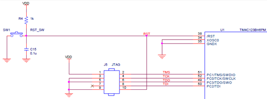
Hi, I'm using TMS320-XDS100v3 JTAG emluator to download to my TM4C123BH6PM MCU.

The schematic is the picture below. (file : 7457.Tiva schematic.pdf)

Some example codes such as LED blinking worked perfectly. However, while using

sometimes error pop-up. The following error is this.

CORTEX_M4_0: JTAG Communication Error: (Error -1170 @ 0x0) Unable to access the DAP. Reset the device, and retry the operation. If error persists, confirm configuration, power-cycle the board, and/or try more reliable JTAG settings (e.g. lower TCLK). (Emulation package 5.1.450.0)

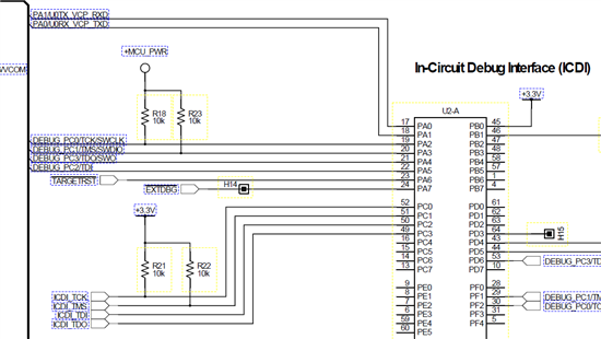
Comparing my circuit and the EK-TM4C123GXL 's schematic, I think I need to insert the pull-up resistors.

(schematic of EK-TM4C123GXL page 22, 5822.EK-TM4C123GXL LaunchPad(LM4F120).pdf)

However, there was something confusing.

At ARM Information site, the descriptions of the pull-up and pull-down settings aredifferent.

(link : http://infocenter.arm.com/help/index.jsp?topic=/com.arm.doc.dui0517b/Cjaeccji.html )

The EK-TM4C123GXL schematic shows that the pull-up resistor is required at the TCK and TMS pins.

On the other hand, the ARM info web says that TMS, TDI, TDO must have pull-ups

and TCK must have pull-down.

- The question is -

1. Placing a Pull-up/down resistor to the JTAG pins are mandatory?

(Some codes have been downloaded sucessfully without the resistors...)

2. If the resistors are needed should the TCK pin needs a pull-up or pull-down?

3. When does this error [CORTEX_M4_0: JTAG Communication Error: Error -1170] occur?

4. The pull-up resistor 1K Ohm at reset switch, does this resistor have to change to 10k Ohm?

Regards, Min-Ku

  • Hello Min-Ku

    1. While some boards do get away w/o having Pull Resistors, it is always a good practice to have the Pull Resistor. I do remember cb1 mentioning the same on a post few weeks back where JTAG was flaky. Some codes may download but sometimes they may not.

    2. TCK pin as per ARM guidelines have a Pull Down so that at power up it does not create a fake TCK pulse. But a Pull Up would also be fine since in case of TM4C123 the JTAG is enabled after the internal POR reset is released.

    3. I am not sure about this error message but, it seems a system reset has occurred during code execution.

    4. A 10K Pull Up Is better for the Reset Switch as it has a reduced leakage current into the Reset pin. However a 10K pull up is a weak pull and can create problem if the circuit/traces around the Reset is noisy.

    Regards

    Amit

  • While we acknowledge the "temptation" to avoid use of external pull-up Rs (relying instead upon MCU's, "weak"internal ones" - our long and repeated findings (ours & @ clients) prove that this method does not prove sufficiently robust. 

    Most everything springs from your successful JTAG (or SWD) operation!  Cost/size of 4, 06-03 pull-up Rs - "pales" in contrast to the lost time/productivity which too often results from this (very false/misguided) external R, "savings."

    And - as your application moves from the (pristine) lab environment to the field (real world) this reliance on internal, MCU R's proves even more risky...  (note: I've no idea why this text has italicized - and cannot reverse that...)
  • Thanks Amit and cb1_.

    Just a couple of more things..

    As Amit mentioned, at no.1  : " I do remember cb1 mentioning the same on a post few weeks back where JTAG was flaky".

    Can you show me the link of your post cb1? I want to read more to aid my study.

    Plus, what do you mean MCU R's(does it mean resistor?) proves even more risky in the real field?

    Do you also have this related link too?

    Thank you all. Regards, Min-Ku

  • My efforts here often result from, "court order/community service" (that's a joke) thus I'm not much motivated to finely track the (beyond) 3K posts which have accumulated.  (another 1K+ under cb1 {static} pennant)

    My "triple threat" sign-on/persona here makes my search/find bit too demanding - don't you agree?  As you express the interest - and as I've already, "contributed/tried to be of some value" via posts proving to your interest/benefit - might such search better be done by you?

    Indeed MCU R's is shorthand for (we believe) very necessary "external pull-up resistors" emplaced very close to the targeted, MCU's JTAG/SWD pins.  Note - we follow this (external pull-up R guideline) across multiple ARM MCUs - (both this vendor and others).  (this guide is no knock upon this vendor - we find this need - and benefit - universally applicable.)

    Usually most lab or development environments are less hostile to critical signals than the, "real world."  With the addition of motors, power actuators, strong/nearby RF signals and other noise sources (all of the above "reasonably present" w/in real world) any weak pull-up resistor may suffer reduced signal margin - and MCU behavior may become erratic.

    In business/law school often the concept of, "risk-reward" is studied.  Savings (cost/size) yielded by the exclusion of external pull-up resistors way too often subject your project/product to grave & uncertain risks - thus the "risk-reward" analysis dictates use of (reliable) external resistors...

  • Hi cb1_

    LOL.. 3K posts?!

    I see. I REALLY did a ridiculous demand.... I'll find the post by my eager of study (hope someday....).

    While reading, I was surprised. Actually, I have some troublesome as you said "erratic".

    After connecting a DC motor, the voltage level of VDD and GND fluctuate.

    (link : http://e2e.ti.com/support/microcontrollers/tiva_arm/f/908/p/332964/1219065.aspx#1219065 )

    Anyway, (Looks like I babbled to much) I was comparing my schematic with the EK-TM4C123GXL.

    The difference was the 3.3V regulator and the JTAG pull-ups.

    In short, I wanted to assume the "erratic behavior" was due to the absence of the pull-ups.

    You mentioned "any weak pull-up resistor may suffer reduced signal margin".

    I never thought of this shortcome. So I'm looking forward to test out and try to figure out to solve this.

    Thank you very much!

    Regards, Min-Ku

  • Stand by the, "Use external JTAG/SWD resistors, always" suggestion

    Yet - as you add motor and "fluctuating Vdd level" new/additional concerns rise.

    Can we "end" this thread w/this writing?

    Suggest you start new thread w/your potentially, "erratic MCU behavior" as title.

    Always best to use KISS (have I - past - ever so briefly mentioned?)  Let's first insure that your MCU runs properly/robustly w/out the motor powered and connected.  Again - so as not to contaminate this post - kindly start anew - as outlined.  (no charge for working/properly communicating title...)