This thread has been locked.

If you have a related question, please click the "Ask a related question" button in the top right corner. The newly created question will be automatically linked to this question.

RTOS/EK-TM4C123GXL: Defined Interrrupt. # 17

Part Number: EK-TM4C123GXL
Other Parts Discussed in Thread: SYSBIOS

Tool/software: TI-RTOS

Dear TI Support team,

 I am new to TI - RTOS . while configuring Hardware interrupt . I'm getting an console log of 

defined: intr# 17
ti.sysbios.family.arm.m3.Hwi: line 143:

after flashing code to the board.

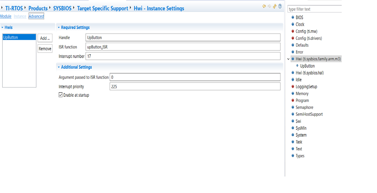
I have defined the interrupt only once via static configuration. Here I am attaching screen shot of the same.

 Please help in this issue.

Thanks and Regards,

Yashwanth Kumar.

  • The console output seems to be truncated for some reason. It should be "E_alreadyDefined: Hwi already defined: intr# 17". It means that that Hwi has already been configured for use.

    What peripheral is this tied to?

    Does this happen every time you load and run the application or only after a restart?

    Is there a Hwi_create(17, ...) in the runtime code as well? This isn't necessary if you're defining the Hwi statically.

    Alan
  • Hi Alan,

    Thank you for your reply.

    1.What peripheral is this tied to?
    I tried to use it for button interrupt from launch pad.

    2. Does this happen every time you load and run the application or only after a restart?
    Yes it is happening for every time i load and run the application.

    Is there a Hwi_create(17, ...) in the runtime code as well?
    No, Only in the app.cfg file.


    Pin configuration used as it existing in the "EK_TM4C123GXL.c" file :

    GPIO_PinConfig gpioPinConfigs[] = {
    /* Input pins */
    /* EK_TM4C123GXL_GPIO_SW1 */
    GPIOTiva_PB_0 | GPIO_CFG_IN_PU | GPIO_CFG_IN_INT_RISING,
    /* EK_TM4C123GXL_GPIO_SW2 */
    GPIOTiva_PB_1 | GPIO_CFG_IN_PU | GPIO_CFG_IN_INT_RISING,

    /* Output pins */
    /* EK_TM4C123GXL_LED_RED */
    GPIOTiva_PF_1 | GPIO_CFG_OUT_STD | GPIO_CFG_OUT_STR_HIGH | GPIO_CFG_OUT_LOW,
    /* EK_TM4C123GXL_LED_BLUE */
    GPIOTiva_PF_2 | GPIO_CFG_OUT_STD | GPIO_CFG_OUT_STR_HIGH | GPIO_CFG_OUT_LOW,
    /* EK_TM4C123GXL_LED_GREEN */
    GPIOTiva_PF_3 | GPIO_CFG_OUT_STD | GPIO_CFG_OUT_STR_HIGH | GPIO_CFG_OUT_LOW
    };

    I am using below code to capture the interrupt.
    Function Declaration :

    extern "C" (I'm using c++ for my project)
    {
    void upButton_ISR();
    }

    Function Definition :

    void upButton_ISR(){

    uint32_t HWI_mask = (GPIOIntStatus(GPIO_PORTB_BASE, 1));

    //Find which gpio pin interred
    GPIOIntClear(GPIO_PORTB_BASE,HWI_mask);

    if(HWI_mask & GPIO_PIN_0){
    GPIO_toggle(Board_LED_BLUE);
    }

    if(HWI_mask & GPIO_PIN_1) {
    GPIO_toggle(Board_LED_GREEN);
    }

    }

    Thanks,
    Yashwanth.
  • Yashwanth,

    1) The GPIO driver will create the required Hwi internally. That is why you are getting the already defined error.

    2) You need to add a GPIO interrupt callback to the goioCallbackFunctions array such as below:

    /*
     *  ======== gpioCallbackFunctions ========
     *  Array of callback function pointers
     *
     */
    extern void mySw1Callback(uint_least8_t index);
    extern void mySw2Callback(uint_least8_t index);
    
    GPIO_CallbackFxn gpioCallbackFunctions[] = {
        /* Board_GPIO0 */
        mySw1Callback,
        /* Board_GPIO1 */
        mySw2Callback,
    };


    3) The callbacks do not need to clear the interrupt as this is done internally by the GPIO driver prior to calling the callback.

    4) In your application use GPIO_enableInt(0) and GPIO_enableInt(1) to enable the interrupts associated with your two callbacks.

    5) Do not use native GPIO driverlib calls unless you absolutely have to. The GPIO driver is designed to manage the state of the pins. If you call a driverlib API directly, the GPIO driver may become out of step with the current state of the GPIO pins it is managing.

    Alan

  • Hi Alan,

    Thanks a lot for your clear explanation of issue.

    Can you help me in how to configure the SW1 (Board button) for HWI using static TI-RTOS config?

    I want to use Port B Pin 0 for SW1. According to Datasheet , GPIO Port B having interrupt number 17 . So I tried to config as above screenshot(Static way of configuring RTOS).

    Please guide me in this path.

    Regards,
    Yashwanth.
  • I'm confused. If you're using the GPIO driver, you should not be configuring the Hwi statically in your config file.

    The "EK_TM4C123GXL.c" board file contents you've shown look correct for the GPIO driver managing PB0 and PB1. You just need to add the interrupt callbacks as I mentioned.

    Alan
  • Yashwanth,

    Did this get resolved?

    Todd