This thread has been locked.

If you have a related question, please click the "Ask a related question" button in the top right corner. The newly created question will be automatically linked to this question.

TM4C123GH6PM: Problem during simulatenously sampling using both the ADCs

Part Number: TM4C123GH6PM

Hello, I was trying to use both the ADCs present on the board to sample two input signals. The logic which I was able to build from my experience of sampling using a single ADCs is that, I am using the same interrupt to trigger both the ADCs and starting simultaneous conversion. In single while loop, I am sampling one signal taking the other one and sampling it as well and ending the conversion. The problem which I think I will face is Jitter, since during instruction cycle of fetching and sampling there might be some inaccuracies created. How can I reduce that? Can I receive guidance with the code as well?

  • Configure each ADC and have them use the same trigger source, such as a timer. Using the CPU to trigger the ADCs will result in jitter and misalignment.

    I can answer technical questions about how to use our TivaWare drivers, but I do not do code reviews or debug software for you.
  • Sir, how can I use the TivaWare Drivers (or if there is any other method) to trigger both the ADCs simulatenously without any jitter?
  • Part Number: TM4C123GH6PM

    I intend to sample two incoming input signals using both the ADCs in the the board. I want to sample both of them simulatenously without any jitter. Is there any effective method to do so? If so, can you suggest me something and provide me some kind of reference code?

  • Hello Soumyadeb,

    If you make use of timers you can setup the ADCs to do sample at the same interval, and then you would have to read in the values after the sampling is done.

    Note that timers are a hard requirement for that use case as this is a single core MCU, and you have to rely on timers to allow multiple peripherals to run side by side.

    We have a project that gets you part of the way there, it does just one channel and also uses the DMA, you can adjust this to meet your project better: 2084.ADCwDMA.zip

    Also there will always be some jitter present, MCU ADC's are meant to be functional and practical for most applications but do not have the precision or speed of specially designed external ADC's. You would need to determine if the jitter present on the results is too much or not.

    If that is truly a large concern for you, I would recommend you look into TI's ADC portfolio and find a device that will meet your strict jitter requirements: www.ti.com/.../overview.html

  • No such example exists but you can take a look at using ADC_TRIGGER_WAIT and ADC_TRIGGER_SIGNAL. See below. In you ADC0, configure a sample sequencer for the first signal and trigger it with the processor using the ADC_TRIGGER_WAIT flag. In your ADC1 configure a sample sequencer for the second signal and trigger with the processor using the ADC_TRIGGER_SIGNAL flag. Try it and see if it works and share with the community your working code. 

  • Hi Charles,

    Actually found example code which I added to my prior post now! Also revised my comments about sequential vs simultaneous to account for using a timer trigger as another means to do sequential samplings.
  • Sir, would it be better to use ADC Interrupts instead of Timer interrupts to increase the efficiency?
  • If the purpose is to convert two values at the same time, ADC interrupts do not help. You get the interrupt after the conversion completes. You have two options.
    Option 1: If you need periodic conversions, such as you are going to do FFT. In this case use a timer that starts both conversions. That way you have a fixed sample rate. Note that the ADCs are not started by an interrupt, but by a hardware flag from the timer.
    Option 2: If you only need a single point, or random point interrupts. In this case you can start the two ADCs with a software request. You use the ADC_TRIGGER_WAIT option when starting the first ADC. That way it waits for the second ADC and the two start together.

    You can certainly use the ADC interrupts to trigger a read of the results.
  • But uDMA can be used at a time for single ADC right? If I intend to use both the samplers at the same time uDMA would not be of help I believe. So, how can use the TIMER to initiate both the cconversions?
  • The uDMA can be used on both ADCs. It is used to read the results. To get simultaneous conversions you need to start both ADCs at the same time, but it is not necessary to read the results at the same time. The uDMA will read the results sequentially.

    Ralph previously posted an example of using a timer to trigger the ADC and using uDMA to read the results.

  • //*****************************************************************************
    //
    // project0.c - Example to demonstrate minimal TivaWare setup
    //
    // Copyright (c) 2012-2017 Texas Instruments Incorporated.  All rights reserved.
    // Software License Agreement
    // 
    // Texas Instruments (TI) is supplying this software for use solely and
    // exclusively on TI's microcontroller products. The software is owned by
    // TI and/or its suppliers, and is protected under applicable copyright
    // laws. You may not combine this software with "viral" open-source
    // software in order to form a larger program.
    // 
    // THIS SOFTWARE IS PROVIDED "AS IS" AND WITH ALL FAULTS.
    // NO WARRANTIES, WHETHER EXPRESS, IMPLIED OR STATUTORY, INCLUDING, BUT
    // NOT LIMITED TO, IMPLIED WARRANTIES OF MERCHANTABILITY AND FITNESS FOR
    // A PARTICULAR PURPOSE APPLY TO THIS SOFTWARE. TI SHALL NOT, UNDER ANY
    // CIRCUMSTANCES, BE LIABLE FOR SPECIAL, INCIDENTAL, OR CONSEQUENTIAL
    // DAMAGES, FOR ANY REASON WHATSOEVER.
    // 
    // This is part of revision 2.1.4.178 of the EK-TM4C123GXL Firmware Package.
    //
    //*****************************************************************************
    
    #include <stdbool.h>
    #include <stdint.h>
    #include "inc/hw_ints.h"
    #include "inc/hw_memmap.h"
    #include "inc/hw_adc.h"
    #include "inc/hw_types.h"
    #include "inc/hw_udma.h"
    #include "driverlib/debug.h"
    #include "driverlib/gpio.h"
    #include "driverlib/interrupt.h"
    #include "driverlib/pin_map.h"
    #include "driverlib/sysctl.h"
    #include "driverlib/uart.h"
    #include "driverlib/adc.h"
    #include "driverlib/udma.h"
    #include "driverlib/timer.h"
    #include "driverlib/rom.h"
    #include "driverlib/rom_map.h"
    #include "driverlib/systick.h"
    #include "utils/uartstdio.h"
    //*****************************************************************************
    //
    // Define pin to LED color mapping.
    //
    //*****************************************************************************
    
    //*****************************************************************************
    //
    //! \addtogroup example_list
    //! <h1>Project Zero (project0)</h1>
    //!
    //! This example demonstrates the use of TivaWare to setup the clocks and
    //! toggle GPIO pins to make the LED's blink. This is a good place to start
    //! understanding your launchpad and the tools that can be used to program it.
    //
    //*****************************************************************************


    //*****************************************************************************
    //
    // The error routine that is called if the driver library encounters an error.
    //
    //*****************************************************************************
    #ifdef DEBUG
    void
    __error__(char *pcFilename, uint32_t ui32Line)
    {
    }
    #endif
    
    //*****************************************************************************
    //
    // Main 'C' Language entry point.  Toggle an LED using TivaWare.
    //
    //*****************************************************************************
    uint32_t adcbuffer[1000];
    uint32_t adcdata1[1000];
    uint32_t adcdata2[1000];
    uint32_t i,timebase,triglvl,xpos,res0,res1;
    
    
    void main(){
    
    
        SysCtlClockSet(SYSCTL_SYSDIV_10 | SYSCTL_USE_PLL | SYSCTL_OSC_MAIN | SYSCTL_XTAL_16MHZ); //20 MHz clock
    
        SysCtlPeripheralEnable(SYSCTL_PERIPH_ADC0);
        SysCtlPeripheralEnable(SYSCTL_PERIPH_ADC1);
        SysCtlPeripheralEnable(SYSCTL_PERIPH_GPIOE);
        SysCtlPeripheralEnable(SYSCTL_PERIPH_GPIOF);
    
            GPIOPinTypeADC(GPIO_PORTE_BASE, GPIO_PIN_3);
            GPIOPinTypeADC(GPIO_PORTE_BASE, GPIO_PIN_2);
            GPIOPinTypeGPIOOutput(GPIO_PORTF_BASE, GPIO_PIN_1);
            GPIOPinTypeGPIOOutput(GPIO_PORTF_BASE, GPIO_PIN_4);
    
            ADCSequenceDisable(ADC0_BASE, 3);


        //Timer Configuration
        SysCtlPeripheralEnable(SYSCTL_PERIPH_TIMER0);
    
    
         TimerConfigure(TIMER0_BASE,TIMER_CFG_PERIODIC);
    
        TimerLoadSet(TIMER0_BASE, TIMER_A,12);          //set the timer to fs=2 ksps load value
    
                                                             //if timer loading value=5000; fs=1 ksps
                                                             // sysclock=20mhz so tsys=1/2000000sec;to get 1ms delay
                                                             //we need to load timer with 1ms/0.5us
    
          TimerEnable(TIMER0_BASE, TIMER_A);


               // ADCSequenceDisable(ADC0_BASE, 3);
               // ADCClockConfigSet(ADC0_BASE, ADC_CLOCK_SRC_PLL | ADC_CLOCK_RATE_FULL, 266);
    
    
                ADCSequenceConfigure(ADC0_BASE, 3, ADC_TRIGGER_PROCESSOR, 0);
                ADCSequenceConfigure(ADC1_BASE, 3, ADC_TRIGGER_PROCESSOR, 0);
    
                ADCSequenceStepConfigure(ADC0_BASE, 3, 0, ADC_CTL_CH7 | ADC_CTL_IE | ADC_CTL_END);
                ADCSequenceStepConfigure(ADC1_BASE, 3, 0, ADC_CTL_CH6 | ADC_CTL_IE | ADC_CTL_END);
                ADCSequenceStepConfigure(ADC1_BASE, 3, 0, ADC_CTL_CH5 | ADC_CTL_IE | ADC_CTL_END);
                ADCSequenceStepConfigure(ADC1_BASE, 3, 0, ADC_CTL_CH4 | ADC_CTL_IE | ADC_CTL_END);
                ADCSequenceStepConfigure(ADC0_BASE, 3, 0, ADC_CTL_CH3 | ADC_CTL_IE | ADC_CTL_END);
    
                ADCSequenceEnable(ADC0_BASE, 3);
                ADCSequenceEnable(ADC1_BASE, 3);
    
                ADCIntClear(ADC0_BASE, 3);
    
    
            while(1)
            {
                ADCSequenceStepConfigure(ADC1_BASE, 3, 0, ADC_CTL_CH5 | ADC_CTL_IE | ADC_CTL_END);
                ADCIntClear(ADC1_BASE, 3);
                ADCProcessorTrigger(ADC1_BASE, 3);                  // Trigger the ADC conversion.
                while(!ADCIntStatus(ADC1_BASE, 3, false)){}         // Wait for conversion to be completed.
                ADCIntClear(ADC1_BASE, 3);                      // Clear the ADC interrupt flag.
                ADCSequenceDataGet(ADC1_BASE, 3, adcbuffer);                // Read ADC Value.
                timebase = adcbuffer[0];
    
                ADCSequenceStepConfigure(ADC1_BASE, 3, 0, ADC_CTL_CH4 | ADC_CTL_IE | ADC_CTL_END);
                ADCIntClear(ADC1_BASE, 3);
                ADCProcessorTrigger(ADC1_BASE, 3);                  // Trigger the ADC conversion.
                while(!ADCIntStatus(ADC1_BASE, 3, false)){}             // Wait for conversion to be completed.
                ADCIntClear(ADC1_BASE, 3);                      // Clear the ADC interrupt flag.
                ADCSequenceDataGet(ADC1_BASE, 3, adcbuffer);                // Read ADC Value.
                triglvl = adcbuffer[0];
    
                ADCSequenceStepConfigure(ADC0_BASE, 3, 0, ADC_CTL_CH3 | ADC_CTL_IE | ADC_CTL_END);
                ADCIntClear(ADC0_BASE, 3);
                ADCProcessorTrigger(ADC0_BASE, 3);                  // Trigger the ADC conversion.
                while(!ADCIntStatus(ADC0_BASE, 3, false)){}             // Wait for conversion to be completed.
                ADCIntClear(ADC0_BASE, 3);                      // Clear the ADC interrupt flag.
                ADCSequenceDataGet(ADC0_BASE, 3, adcbuffer);                // Read ADC Value.
                xpos = adcbuffer[0];
    
                for (i=0;i<=1000;i++)
                {
                    ADCSequenceStepConfigure(ADC0_BASE, 3, 0, ADC_CTL_CH7 | ADC_CTL_IE | ADC_CTL_END);
                    ADCIntClear(ADC0_BASE, 3);
                    ADCProcessorTrigger(ADC0_BASE, 3);              // Trigger the ADC conversion.
                    while(!ADCIntStatus(ADC0_BASE, 3, false)){}         // Wait for conversion to be completed.
                    ADCIntClear(ADC0_BASE, 3);                  // Clear the ADC interrupt flag.
                    ADCSequenceDataGet(ADC0_BASE, 3, adcbuffer);            // Read ADC Value.
                    adcdata1[i] = adcbuffer[0];
                    res0=adcdata1[i];
                //  GPIOPinWrite(GPIO_PORTF_BASE,GPIO_PIN_1, res0);
    
                    ADCSequenceStepConfigure(ADC1_BASE, 3, 0, ADC_CTL_CH6 | ADC_CTL_IE | ADC_CTL_END);
                    ADCIntClear(ADC1_BASE, 3);
                    ADCProcessorTrigger(ADC1_BASE, 3);              // Trigger the ADC conversion.
                    while(!ADCIntStatus(ADC1_BASE, 3, false)){}         // Wait for conversion to be completed.
                    ADCIntClear(ADC1_BASE, 3);                  // Clear the ADC interrupt flag.
                    ADCSequenceDataGet(ADC1_BASE, 3, adcbuffer);            // Read ADC Value.
                    adcdata2[i] = adcbuffer[0];
                    res1=adcdata2[i];
                   //GPIOPinWrite(GPIO_PORTF_BASE,GPIO_PIN_4, res1);
                }
            }
    }


    .

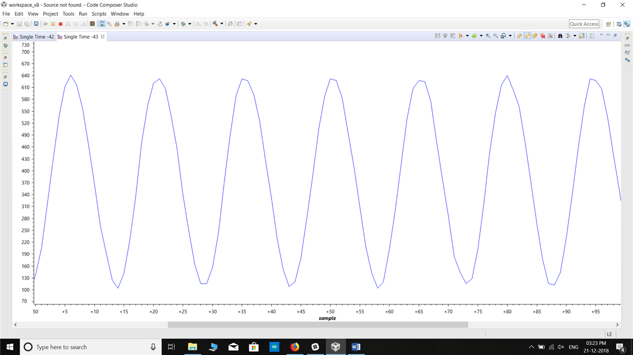
    Thankyou Sir. I was able to sample using both the ADCs. This is my current code. But I am observing distortion in the sampled signals and I am unable to figure out the reason.

  • Update: Sir, I was able to get an approximate reconstructed signal but I am getting delay between two output of the ADC. Is there any way I could minimise the delay between both outputs? Because currently I am getting significant delay between the two.

  • You setup the timer, but then used "ADCProcessorTrigger()" in your loop, and you did not use "ADC_TRIGGER_WAIT". For simple CPU trigger of simultaneous conversions the sequence is more like this:

                    ADCProcessorTrigger(ADC0_BASE, 3 | ADC_TRIGGER_WAIT); // Setup the trigger but wait.
                    ADCProcessorTrigger(ADC1_BASE, 3);                    // Trigger both ADC's
                    while(!ADCIntStatus(ADC0_BASE, 3, false)){}         // Wait for conversion to be completed.
                    ADCSequenceDataGet(ADC0_BASE, 3, &adcdata1[i]);            // Read ADC Value.
                    while(!ADCIntStatus(ADC1_BASE, 3, false)){}         // Wait for conversion to be completed.
                    ADCSequenceDataGet(ADC1_BASE, 3, &adcdata2[i]);            // Read ADC Value.


  • Sir, I have used this in the for loop but the values stored
    in adcdata1 and adcdata2 is becoming zero now.
    I am unable see any conversion.

     
    ADCSequenceStepConfigure(ADC0_BASE, 3, 0, ADC_CTL_CH7 | ADC_CTL_IE | ADC_CTL_END);
                    ADCSequenceStepConfigure(ADC1_BASE, 3, 0, ADC_CTL_CH6 | ADC_CTL_IE | ADC_CTL_END);
                    ADCIntClear(ADC0_BASE, 3);
                    ADCIntClear(ADC1_BASE, 3);
                    ADCProcessorTrigger(ADC0_BASE, 3 | ADC_TRIGGER_WAIT); // Setup the trigger but wait.
                    ADCProcessorTrigger(ADC1_BASE, 3);                    // Trigger both ADC's
                    while(!ADCIntStatus(ADC0_BASE, 3, false)){}         // Wait for conversion to be completed.
                    ADCSequenceDataGet(ADC0_BASE, 3, &adcdata1[i]);            // Read ADC Value.
                    adcdata1[i] = adcbuffer[0];
                    while(!ADCIntStatus(ADC1_BASE, 3, false)){}         // Wait for conversion to be completed.
                    ADCSequenceDataGet(ADC1_BASE, 3, &adcdata2[i]);            // Read ADC Value.
                    adcdata2[i] = adcbuffer[0];


  • Why are you overwriting the values in the array with the initial value of adcbuffer[0]? You need to have a basic understanding of what your code is doing. The statement "ADCSequenceDataGet(ADC0_BASE, 3, &adcdata1[i]);" is filling the array adcdata1 with values. Then you overwrite that value with "adcbuffer[0]" which looks uninitialized, and is therefore 0.
  • Sir, I am still getting the values to be zero even if I don't overwrite it.
  • Actually, you should be stuck in the while loop waiting for ADC0. You need to add "ADC_TRIGGER_SIGNAL" to the "ADCProcessorTrigger(ADC1_BASE, 3);" statement. I have attached an example .zip project that does 5 simultaneous conversions of channels AIN0 and AIN1. Use the code composer "File" "Import" function to add this project to your workspace.

    /cfs-file/__key/communityserver-discussions-components-files/908/SimultaneousADC.zip

  • Sir, I have been using the code as it is just to test the functioning but as I am debugging it , it gets redirected to exit.c and goes into abnormal program termination and I cannot determine its reason.
  • Update: I was able to do the simultaneous sampling. But when I used 3.3V as the reference voltage(DC), theoretically I expected a straightline around 4100 in the graphy but I see a straight line around 500. I cannot determine the problem for this.

  • Check you connections. I got the expected 4095.

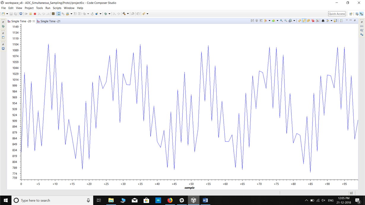
  • Thankyou so much sir! I was able to achieve what I was trying to do. But Sir I am getting a jitter of around 100ms which cause problems in my application. Is there any way to resolve this? Or should go for an external ADC?
  • What do you mean by jitter of 100mS? The two ADCs will sample and convert at the same time. If you mean that the samples are not taken with an exact frequency, that is because you are using the software trigger. To get the samples to be at a precise interval, you need to use the timer to trigger the two ADCs.
  • Thankyou for your support my issue was resolved!!!
    Thanks a lot!