This thread has been locked.

If you have a related question, please click the "Ask a related question" button in the top right corner. The newly created question will be automatically linked to this question.

CCS/EK-TM4C123GXL: Example application to test the SPI flash on TM4C

Part Number: EK-TM4C123GXL
Other Parts Discussed in Thread: TM4C123GH6PM

Tool/software: Code Composer Studio

Hi all,

I'm checking SPI flash(MX25R6435F) on EK-TM4C123GXL connected to SSI0. Using the   in the below link we have ported it for EK-TM4CGXL.

https://e2e.ti.com/support/microcontrollers/other/f/908/p/392228/1469297

Attached the modified project Memory_board.7z

I'm not able to run the debug session on CCS. Resume, suspend and terminate buttons on the toolbar is in the disabled state and i do not have control to the running program.

I'm using code composer studio 8.1.0 version. Other examples are working fine in debug mode using the same setup. 

Basically, we need to validate the SPI flash on TM4C. I appreciate any suggestions.

Thank You.

Regards,

Ambika 

  • I think the root cause of your issue is that you are trying to import a project that uses over 48KB of RAM into a part that has only 32KB of RAM. Your link command file, tm4c123gh6pm.cmd, has the memory sizes of a TM4C129x device, not of a TM4C123 device.

    You will have to reduce the size of "NUM_SSI_DATA", 1024 should work. Also, I suggest you start by importing a project from:
    C:\ti\TivaWare_C_Series-2.1.4.178\examples\boards\ek-tm4c123gxl\project0
    Rename the project, then delete the "project0.c" file and copy in your TM4C129_SSI3_MacronixFlash.c file and your uartstdio.c and .h. That way you will have the proper startup files and proper link command file.
  • Hi Bob,

    Thanks very much.

    I'm able to solve the debugging issue. The modification required for our setup is done. Please note that we are using single IO SPI whereas reference code used from the link is implemented for QSPI. We are facing below issues:

    • When Bitrate is set for 16MHz as below, SSIConfigSetExpClk() function never returns.

    SSIConfigSetExpClk(SSI0_BASE, SysCtlClockGet(), SSI_FRF_MOTO_MODE_0, SSI_MODE_MASTER, 16000000, 8);

    • Then I tried changing bitrate to 1MHz and 2MHz then, SSIConfigSetExpClk() returns to the main functions but ui32MfgID and ui32DevID read as 0 inside function SSILibSendReadIDAdvMode(). As per SPI flash device datasheet, ui32MfgID = C2 and ui32DevID = 17.
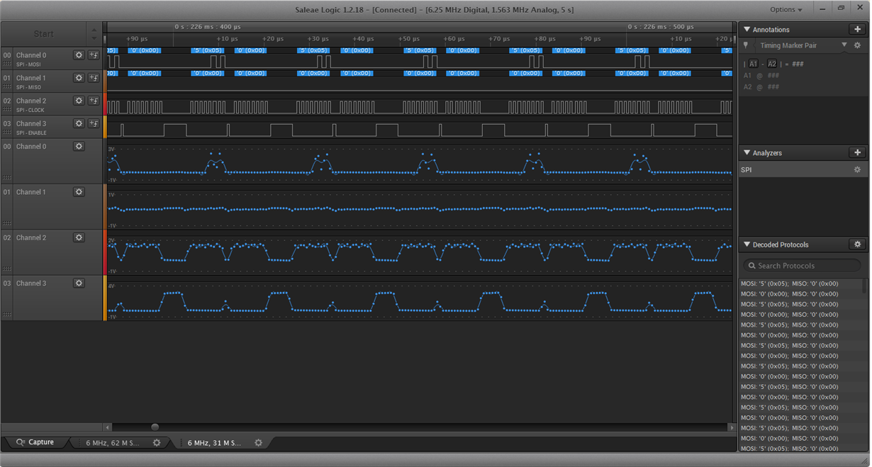
    • We are sending 90h followed by 3 bytes of 00h while reading device ID (SSILibSendReadIDAdvMode()) but we never saw 90h data on MOSI line in LA.

    FYR: Attached code and captured image of LA.

    Kindly help us to solve this problem.

    2577.TM4C129_SSI3_MacronixFlash.c
    #include <stdlib.h>
    #include <stdint.h>
    #include <stdbool.h>
    #include "inc/hw_memmap.h"
    #include "inc/hw_types.h"
    #include "inc/hw_gpio.h"
    #include "inc/hw_ssi.h"
    #include "inc/hw_sysctl.h"
    #include "inc/hw_epi.h"
    #include "inc/hw_ints.h"
    #include "inc/hw_nvic.h"
    #include "inc/hw_uart.h"
    #include "driverlib/debug.h"
    #include "driverlib/fpu.h"
    #include "driverlib/gpio.h"
    #include "driverlib/rom.h"
    #include "driverlib/rom_map.h"
    #include "driverlib/interrupt.h"
    #include "driverlib/pin_map.h"
    #include "driverlib/sysctl.h"
    #include "driverlib/ssi.h"
    #include "driverlib/uart.h"
    #include "utils/uartstdio.h"
    #include "driverlib/eeprom.h"
    
    #define NUM_SSI_DATA                1024
    #define INS_WRITE_ENABLE            0x06
    #define INS_READ_STATUS_REGISTER1   0x05
    #define DUMMY_BYTE                  0x00
    #define FLASH_BUSY_BIT              0x01
    #define FLASH_WRITE_EN_LATCH_BIT    0x02
    #define INS_SECTOR_ERASE_4KB        0xD8 // 0x20
    #define INS_ERASE_FULL              0xC7
    #define INS_PAGE_PROGRAM            0x02
    #define INS_READ_DATA               0x03
    
    #define FLAG_EEPROM_START       0x400
    
    #define BST (+1)
    #define CCT (+8)
    
    uint8_t g_ui8InstrReadID[] = {0x90,0x00,0x00,0x00};
    uint32_t pui32DataTx1[NUM_SSI_DATA],pui32DataTx2[NUM_SSI_DATA],pui32DataTx3[NUM_SSI_DATA];
    uint32_t pui32DataRx1[NUM_SSI_DATA],pui32DataRx2[NUM_SSI_DATA],pui32DataRx3[NUM_SSI_DATA];
    uint32_t pui32Dummy[1];
    uint32_t ui32Index;
    uint32_t ui32DeviceID;
    uint32_t ui32SysClockFreq;
    
    //*****************************************************************************
    //
    // This function sets up SSI External Flash ID Read
    //
    //*****************************************************************************
    uint32_t SSILibSendReadIDAdvMode(uint32_t ui32Base)
    {
       uint32_t ui32Idx, ui32Receive;
       uint32_t ui32MfgID;
       uint32_t ui32DevID;
       uint32_t ui32ReadID[]={0xaa,0xaa};
       uint32_t ui32ReadIDFlash;
    
       for(ui32Idx = 0; ui32Idx < sizeof(g_ui8InstrReadID) / sizeof(g_ui8InstrReadID[0]); ui32Idx++)
       {
         SSIDataPut(ui32Base, g_ui8InstrReadID[ui32Idx]);
       }
    
       SSIAdvModeSet(ui32Base,SSI_ADV_MODE_READ_WRITE);
       SSIDataPut(ui32Base, 0x00);
       SSIDataGet(ui32Base, &ui32Receive);
       ui32ReadID[0] = ui32Receive;
       SSIAdvDataPutFrameEnd(ui32Base,0x00);
       SSIDataGet(ui32Base, &ui32Receive);
       ui32ReadID[1] = ui32Receive;
       ui32MfgID = ui32ReadID[0];
       ui32DevID = ui32ReadID[1];
       ui32ReadIDFlash = ui32MfgID;
    
       ui32ReadIDFlash = ui32ReadIDFlash << 8;
       ui32ReadIDFlash |= ui32DevID;
    
       SSIAdvModeSet(SSI0_BASE,SSI_ADV_MODE_WRITE);
    
       return ui32ReadIDFlash;
    }
    
    uint8_t
    SSILibSendReadStatusRegister(uint32_t ui32Base, uint8_t ui8FlashCommand)
    {
        uint32_t ui32Status = 0;
        uint8_t ui8FlashStatus;
    
        SSIAdvFrameHoldEnable(ui32Base);
        SSIDataPut(ui32Base,ui8FlashCommand);
        SSIAdvModeSet(ui32Base,SSI_ADV_MODE_READ_WRITE);
        SSIAdvDataPutFrameEnd(ui32Base,DUMMY_BYTE);
        while(SSIBusy(ui32Base));
        SSIDataGet(ui32Base, &ui32Status);
        ui8FlashStatus = (uint8_t)ui32Status;
        SSIAdvModeSet(SSI0_BASE,SSI_ADV_MODE_WRITE);
    
        return ui8FlashStatus;
    }
    
    
    void
    SSILibDeviceBusyCheck(uint32_t ui32Base)
    {
       uint8_t ui8TempData=0xFF;
    
       ui8TempData = SSILibSendReadStatusRegister(ui32Base,INS_READ_STATUS_REGISTER1);
    
       while((ui8TempData & FLASH_BUSY_BIT) == FLASH_BUSY_BIT)
       {
          ui8TempData = SSILibSendReadStatusRegister(ui32Base,INS_READ_STATUS_REGISTER1);
       }
    }
    
    void
    SSILibSendPageProgram(uint32_t ui32Base, uint32_t ui32Address, uint8_t ui8FlashCommand)
    {
        uint32_t ui32TempAddr, ui32TempData;
        uint8_t ui8AddrByte1, ui8AddrByte2, ui8AddrByte3;
    
        ui32TempAddr = ui32Address >> 16 ;
        ui8AddrByte1 = (uint8_t)ui32TempAddr;
        ui32TempAddr = ui32Address >> 8 ;
        ui8AddrByte2 = (uint8_t)ui32TempAddr;
        ui8AddrByte3 = (uint8_t)ui32Address;
    
        SSIAdvModeSet(SSI0_BASE,SSI_ADV_MODE_WRITE);
        SSIAdvFrameHoldEnable(ui32Base);
        SSIAdvDataPutFrameEnd(ui32Base,INS_WRITE_ENABLE);
        while(SSIBusy(ui32Base));
    
        ui32TempData = SSILibSendReadStatusRegister(ui32Base,INS_READ_STATUS_REGISTER1);
        while((ui32TempData & FLASH_WRITE_EN_LATCH_BIT) != FLASH_WRITE_EN_LATCH_BIT) {
          ui32TempData = SSILibSendReadStatusRegister(ui32Base,INS_READ_STATUS_REGISTER1);
        }
    
        SSIAdvModeSet(SSI0_BASE,SSI_ADV_MODE_WRITE);
        SSIAdvFrameHoldEnable(ui32Base);
        SSIDataPut(ui32Base,ui8FlashCommand);
        SSIDataPut(ui32Base,ui8AddrByte1);
        SSIDataPut(ui32Base,ui8AddrByte2);
        SSIDataPut(ui32Base,ui8AddrByte3);
    }
    
    void
    SSILibSendReadDataAdvBi(uint32_t ui32Base, uint32_t ui32Address, uint8_t ui8FlashCommand)
    {
        uint32_t ui32TempAddr;
        uint8_t ui8AddrByte1, ui8AddrByte2, ui8AddrByte3;
    
        ui32TempAddr = ui32Address >> 16 ;
        ui8AddrByte1 = (uint8_t)ui32TempAddr;
        ui32TempAddr = ui32Address >> 8 ;
        ui8AddrByte2 = (uint8_t)ui32TempAddr;
        ui8AddrByte3 = (uint8_t)ui32Address;
        SSIAdvModeSet(SSI0_BASE,SSI_ADV_MODE_WRITE);
        SSIAdvFrameHoldEnable(ui32Base);
        SSIDataPut(ui32Base,ui8FlashCommand);
        SSIDataPut(ui32Base,ui8AddrByte1);
        SSIDataPut(ui32Base,ui8AddrByte2);
        SSIDataPut(ui32Base,ui8AddrByte3);
    
        SSIAdvModeSet(ui32Base,SSI_ADV_MODE_READ_WRITE);
    }
    
    
    //*****************************************************************************
    //
    // This function sets up SSI External Flash Erase
    //
    //*****************************************************************************
    void
    SSILibSendEraseCommand (uint32_t ui32Base, uint32_t ui32Address, uint8_t ui8FlashCommand)
    {
        uint32_t ui32TempAddr, ui32TempData;
        uint8_t ui8AddrByte1, ui8AddrByte2, ui8AddrByte3;
    
        ui32TempAddr = ui32Address >> 16 ;
    
        ui8AddrByte1 = (uint8_t)ui32TempAddr;
        ui32TempAddr = ui32Address >> 8 ;
        ui8AddrByte2 = (uint8_t)ui32TempAddr;
        ui8AddrByte3 = (uint8_t)ui32Address;
    
        SSIAdvModeSet(SSI0_BASE,SSI_ADV_MODE_WRITE);
        SSIAdvFrameHoldEnable(ui32Base);
        SSIAdvDataPutFrameEnd(ui32Base,INS_WRITE_ENABLE);
        while(SSIBusy(ui32Base));
    
        ui32TempData = SSILibSendReadStatusRegister(ui32Base,INS_READ_STATUS_REGISTER1);
        while((ui32TempData & FLASH_WRITE_EN_LATCH_BIT) != FLASH_WRITE_EN_LATCH_BIT) {
          ui32TempData = SSILibSendReadStatusRegister(ui32Base,INS_READ_STATUS_REGISTER1);
        }
    
        SSIAdvModeSet(SSI0_BASE,SSI_ADV_MODE_WRITE);
        SSIAdvFrameHoldEnable(ui32Base);
        SSIDataPut(ui32Base,ui8FlashCommand);
        SSIDataPut(ui32Base,ui8AddrByte1);
        SSIDataPut(ui32Base,ui8AddrByte2);
        SSIAdvDataPutFrameEnd(ui32Base,ui8AddrByte3);
        while(SSIBusy(ui32Base));
        //wait till the erase is completed
        SSILibDeviceBusyCheck(ui32Base);
    
    }
    
    //*****************************************************************************
    //
    // This function sets up UART0 to be used for a console to display information
    // as the example is running.
    //
    //*****************************************************************************
    void
    InitConsole(void)
    {
        //
        // Enable GPIO port A which is used for UART0 pins.
        // TODO: change this to whichever GPIO port you are using.
        //
        SysCtlPeripheralEnable(SYSCTL_PERIPH_GPIOA);
    
        //
        // Configure the pin muxing for UART0 functions on port A0 and A1.
        // This step is not necessary if your part does not support pin muxing.
        // TODO: change this to select the port/pin you are using.
        //
        GPIOPinConfigure(GPIO_PA0_U0RX);
        GPIOPinConfigure(GPIO_PA1_U0TX);
    
        //
        // Enable UART0 so that we can configure the clock.
        //
        SysCtlPeripheralEnable(SYSCTL_PERIPH_UART0);
    
        //
        // Use the internal 16MHz oscillator as the UART clock source.
        //
        UARTClockSourceSet(UART0_BASE, UART_CLOCK_PIOSC);
    
        //
        // Select the alternate (UART) function for these pins.
        // TODO: change this to select the port/pin you are using.
        //
        GPIOPinTypeUART(GPIO_PORTA_BASE, GPIO_PIN_0 | GPIO_PIN_1);
    
        //
        // Initialize the UART for console I/O.
        //
        UARTStdioConfig(0, 115200, 16000000);
    }
    
    //*****************************************************************************
    //
    // Configure SSI3 in master Freescale (SPI) mode.  This example will send out
    // 3 bytes of data, then wait for 3 bytes of data to come in.  This will all be
    // done using the polling method.
    //
    //*****************************************************************************
    int
    main(void)
    {
    
        //
        // Set the clocking to run directly from the external crystal/oscillator.
        // TODO: The SYSCTL_XTAL_ value must be changed to match the value of the
        // crystal on your board.
        //
        //ui32SysClockFreq = MAP_SysCtlClockFreqSet((SYSCTL_XTAL_25MHZ | SYSCTL_OSC_MAIN |SYSCTL_USE_PLL |
          //      SYSCTL_CFG_VCO_480), 120000000);
    
        //
        // Set the clocking to run directly from the external crystal/oscillator.
        // TODO: The SYSCTL_XTAL_ value must be changed to match the value of the
        // crystal on your board.
        //
        SysCtlClockSet(SYSCTL_SYSDIV_10 | SYSCTL_USE_PLL | SYSCTL_OSC_MAIN |
                SYSCTL_XTAL_16MHZ);
    
        //
        // Set up the serial console to use for displaying messages.  This is
        // just for this example program and is not needed for SSI operation.
        //
        InitConsole();
    
        //
        // Display the setup on the console.
        //
      //  UARTprintf("SSI3 To DK-TM4C129 FLASH TRANSFER\n");
    
        //
        // The SSI3 peripheral must be enabled for use.
        //
    
        SysCtlPeripheralEnable(SYSCTL_PERIPH_SSI0);
    
        //
        // For this SSI0 is used with Port B, D and E.
        //
    #if 0
        SysCtlPeripheralEnable(SYSCTL_PERIPH_GPIOB);
        SysCtlPeripheralEnable(SYSCTL_PERIPH_GPIOE);
        SysCtlPeripheralEnable(SYSCTL_PERIPH_GPIOD);
    #endif
    
        SysCtlPeripheralEnable(SYSCTL_PERIPH_GPIOA);
        SysCtlPeripheralEnable(SYSCTL_PERIPH_GPIOE);
    
        //
        // GPIO Port E0 Pin is Locked. So Unlock and write the CR bit
        //
        HWREG(GPIO_PORTE_BASE+GPIO_O_LOCK) = GPIO_LOCK_KEY;
        HWREG(GPIO_PORTE_BASE+GPIO_O_CR)   |= GPIO_PIN_0;
    
        //
        // Configure the pin muxing for SSI0 functions on port B4, B5, E4, E5, D4, D5
        //
    #if 0
        GPIOPinConfigure(GPIO_PB5_SSI0CLK);
        GPIOPinConfigure(GPIO_PB4_SSI0FSS);
        GPIOPinConfigure(GPIO_PE4_SSI0XDAT0);
        GPIOPinConfigure(GPIO_PE5_SSI0XDAT1);
        GPIOPinConfigure(GPIO_PD4_SSI0XDAT2);
        GPIOPinConfigure(GPIO_PD5_SSI0XDAT3);
    #endif
    
        //
        // Configure the pin muxing for SSI0 functions on port A2, A3, A4, and A5.
        // This step is not necessary if your part does not support pin muxing.
        // TODO: change this to select the port/pin you are using.
        //
        GPIOPinConfigure(GPIO_PA2_SSI0CLK);
        GPIOPinConfigure(GPIO_PA3_SSI0FSS);
        GPIOPinConfigure(GPIO_PA4_SSI0RX);
        GPIOPinConfigure(GPIO_PA5_SSI0TX);
    
        //
        // Configure the GPIO settings for the SSI pins.  This function also gives
        // control of these pins to the SSI hardware.  Consult the data sheet to
        // see which functions are allocated per pin.
    #if 0
        GPIOPinTypeSSI(GPIO_PORTB_BASE, GPIO_PIN_5 | GPIO_PIN_4 );
        GPIOPinTypeSSI(GPIO_PORTE_BASE, GPIO_PIN_5 | GPIO_PIN_4 );
        GPIOPinTypeSSI(GPIO_PORTD_BASE, GPIO_PIN_5 | GPIO_PIN_4 );
    #endif
    
        GPIOPinTypeSSI(GPIO_PORTA_BASE, GPIO_PIN_2 | GPIO_PIN_3 | GPIO_PIN_4 | GPIO_PIN_5 );
    
        //
        // Configure and enable the SSI port for SPI master mode.  Use SSI0,
        // system clock supply, idle clock level low and active low clock in
        // freescale SPI mode, master mode, 1MHz SSI frequency, and 8-bit data.
        // For SPI mode, you can set the polarity of the SSI clock when the SSI
        // unit is idle.  You can also configure what clock edge you want to
        // capture data on.  Please reference the datasheet for more information on
        // the different SPI modes.
        //
        SSIConfigSetExpClk(SSI0_BASE, SysCtlClockGet(), SSI_FRF_MOTO_MODE_0,
                           SSI_MODE_MASTER, 1000000, 8);
    
        //
        // Enable the SSI0 module.
        //
        SSIAdvModeSet(SSI0_BASE,SSI_ADV_MODE_WRITE);
        SSIAdvFrameHoldEnable(SSI0_BASE);
        SSIEnable(SSI0_BASE);
    
        //
        // Read any residual data from the SSI port.  This makes sure the receive
        // FIFOs are empty, so we don't read any unwanted junk.  This is done here
        // because the SPI SSI mode is full-duplex, which allows you to send and
        // receive at the same time.  The SSIDataGetNonBlocking function returns
        // "true" when data was returned, and "false" when no data was returned.
        // The "non-blocking" function checks if there is any data in the receive
        // FIFO and does not "hang" if there isn't.
        //
        while(SSIDataGetNonBlocking(SSI0_BASE, &pui32Dummy[0]))
        {
        }
    
        //
        // Initialize the Transmit Buffer
        //
        for(ui32Index=0;ui32Index<NUM_SSI_DATA;ui32Index++)
        {
            pui32DataTx1[ui32Index] = (rand()*rand()) %(256);
            pui32DataTx2[ui32Index] = (rand()*rand()) %(256);
            pui32DataTx3[ui32Index] = (rand()*rand()) %(256);
            pui32DataRx1[ui32Index] = 0x0;
            pui32DataRx2[ui32Index] = 0x0;
            pui32DataRx3[ui32Index] = 0x0;
        }
     /*   SysCtlPeripheralEnable(SYSCTL_PERIPH_EEPROM0);
            if(EEPROMInit() == EEPROM_INIT_OK )
            {
                    uint32_t statusFlag = 0x00;
                    EEPROMProgram(&statusFlag, FLAG_EEPROM_START+0x010, sizeof(statusFlag));
                    EEPROMProgram(&statusFlag, FLAG_EEPROM_START+0x014, sizeof(statusFlag));
            }
     */   //
        // First Read the DEVICE ID
        //
        ui32DeviceID = SSILibSendReadIDAdvMode(SSI0_BASE);
        if(ui32DeviceID != 0x0119)
        {
            UARTprintf("No External Flash... Read Back %x\n",ui32DeviceID);
          //  while(1);
        }
    
        UARTprintf("External Flash Detected with Device ID %x\n",ui32DeviceID);
    
        //
        // Erase the Sector before Program Operation...
        //
        UARTprintf("Starting Erase Operations...\n");
        SSILibSendEraseCommand(SSI0_BASE,0x0,INS_SECTOR_ERASE_4KB);
        UARTprintf("Erase Completed...\n");
    
        //
        // Write NUM_SSI_DATA words to the External Flash
        //
        UARTprintf("Starting Program Operations...\n");
    /*
        int iCnt = NUM_SSI_DATA*3/512;
        int i = 0;
        ui32Index = 0;
        for(i=0; i<iCnt;){
            SSILibSendPageProgram(SSI0_BASE,(i*512),INS_PAGE_PROGRAM);
            i++;
            for(;ui32Index < (i*512)-1; ui32Index++){
                SSIDataPut(SSI0_BASE,pui32DataTx1[ui32Index]);
            }
            SSIAdvDataPutFrameEnd(SSI0_BASE,pui32DataTx1[ui32Index]);
            SysCtlDelay(ui32SysClockFreq/500);
    
            SSILibSendPageProgram(SSI0_BASE,(i*512),INS_PAGE_PROGRAM);
            i++;
            for(;ui32Index < (i*512)-1; ui32Index++){
                SSIDataPut(SSI0_BASE,pui32DataTx2[ui32Index]);
            }
            SSIAdvDataPutFrameEnd(SSI0_BASE,pui32DataTx2[ui32Index]);
            SysCtlDelay(ui32SysClockFreq/500);
    
            SSILibSendPageProgram(SSI0_BASE,(i*512),INS_PAGE_PROGRAM);
            i++;
            for(;ui32Index < (i*512)-1; ui32Index++){
                SSIDataPut(SSI0_BASE,pui32DataTx3[ui32Index]);
            }
            SSIAdvDataPutFrameEnd(SSI0_BASE,pui32DataTx3[ui32Index]);
            SysCtlDelay(ui32SysClockFreq/500);
        }
    */
    /*
        SSILibSendPageProgram(SSI0_BASE,0x0,INS_PAGE_PROGRAM);
        for(ui32Index=0;ui32Index<511;ui32Index++)
        {
            SSIDataPut(SSI0_BASE,pui32DataTx1[ui32Index]);
        }
        SSIAdvDataPutFrameEnd(SSI0_BASE,pui32DataTx1[511]);
        SysCtlDelay(ui32SysClockFreq/500);
        SSILibSendPageProgram(SSI0_BASE,0x200,INS_PAGE_PROGRAM);
        for(ui32Index=512;ui32Index<512*2-1;ui32Index++){
            SSIDataPut(SSI0_BASE,pui32DataTx1[ui32Index]);
        }
        SSIAdvDataPutFrameEnd(SSI0_BASE,pui32DataTx1[NUM_SSI_DATA]);
        SysCtlDelay(ui32SysClockFreq/500);
        SSILibSendPageProgram(SSI0_BASE,0x400,INS_PAGE_PROGRAM);
        for(ui32Index=0;ui32Index<511;ui32Index++)
        {
            SSIDataPut(SSI0_BASE,pui32DataTx2[ui32Index]);
        }
        SSIAdvDataPutFrameEnd(SSI0_BASE,pui32DataTx1[511]);
        SysCtlDelay(ui32SysClockFreq/500);
        SSILibSendPageProgram(SSI0_BASE,0x600,INS_PAGE_PROGRAM);
        for(ui32Index=512;ui32Index<512*2-1;ui32Index++){
            SSIDataPut(SSI0_BASE,pui32DataTx2[ui32Index]);
        }
        SSIAdvDataPutFrameEnd(SSI0_BASE,pui32DataTx2[NUM_SSI_DATA]);
     */
        UARTprintf("Program Completed...\n");
    
        //
        // Read NUM_SSI_DATA words from the External Flash
        //
        UARTprintf("Starting Read Operations...\n");
        SSILibSendReadDataAdvBi(SSI0_BASE,0x0,INS_READ_DATA);
        for(ui32Index=0;ui32Index<NUM_SSI_DATA;ui32Index++)
        {
            SSIDataPut(SSI0_BASE,DUMMY_BYTE);
            SSIDataGet(SSI0_BASE,&pui32DataRx1[ui32Index]);
            SysCtlDelay(ui32SysClockFreq/5000);
        }
        for(ui32Index=0;ui32Index<NUM_SSI_DATA;ui32Index++)
        {
            SSIDataPut(SSI0_BASE,DUMMY_BYTE);
            SSIDataGet(SSI0_BASE,&pui32DataRx2[ui32Index]);
            SysCtlDelay(ui32SysClockFreq/5000);
        }
        for(ui32Index=0;ui32Index<NUM_SSI_DATA;ui32Index++)
            {
                SSIDataPut(SSI0_BASE,DUMMY_BYTE);
                SSIDataGet(SSI0_BASE,&pui32DataRx3[ui32Index]);
                SysCtlDelay(ui32SysClockFreq/5000);
            }
       // SSIAdvDataPutFrameEnd(SSI0_BASE,DUMMY_BYTE);
      //  SSIDataGet(SSI0_BASE,&pui32DataRx[NUM_SSI_DATA-1]);
        UARTprintf("Read Completed...\n");
    
        /*for(ui32Index=0;ui32Index<NUM_SSI_DATA;ui32Index++)
        {
            SSIDataPut(SSI0_BASE,DUMMY_BYTE);
            SSIDataGet(SSI0_BASE,&pui32DataRx[ui32Index+NUM_SSI_DATA]);
        }
        */
     //   SSIAdvDataPutFrameEnd(SSI0_BASE,DUMMY_BYTE);
        //
        // Display Data
        //
        for(ui32Index=0;ui32Index<NUM_SSI_DATA;ui32Index++)
        {
            UARTprintf("Program: %x Read: %x\n",pui32DataTx1[ui32Index],pui32DataRx1[ui32Index]);
        }
    
        UARTprintf("\n End of Programe");
    }
    

    Regads,

    Ambika

  • I suspect that 16MHz is too fast if the devices are on separate PCBs. If you have verified on the logic analyzer that you are getting the correct waveform out of the TM4C, but not out of the Macronix Flash, then please contact Macronix for information on configuring their chip.
  • Sorry, I misread your post. You said that you do not see the correct 0x90 out of the TM4C device.
  • OK, I ran your code (but I do not have a Macronix chip attached). I see the 0x90 command out the SSI. But note in the picture that FSS rises after each byte. That is because the TM4C123 devices do not have the Frame Hold feature like the TM4C129x devices. To match the Macronix requirement using the TM4C123 device, you will need to configure the CS signal as a digital output and drive it at the beginning and end of transmissions with software.

  • Hi Bob,

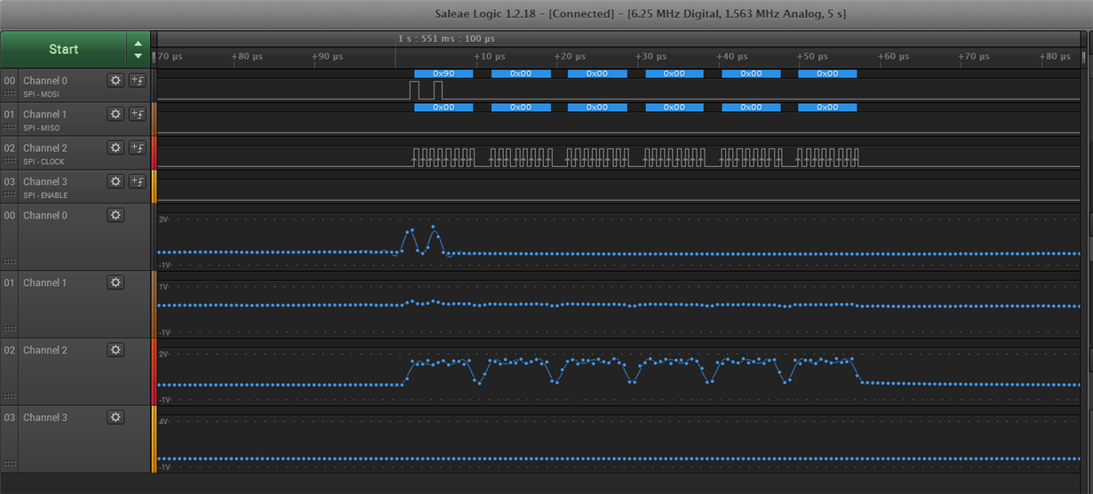
    You are right, we did not observe packets properly on LA. 90h data sent to SPI is seen in the very beginning of samples soon after reset.

    As per your suggestion, we configured CS as GPIO output pin, driven LOW at the beginning of  the transmission and HIGH at the end of transmission

    We are not able to read the device ID, response from the SPI flash on MISO of TM4C is always 0. 

    Attached LA output for your reference.

    Thank You.

    Regards,

    Ambika

  • If the signals going into the Macronix chip are correct, but the response from the Macronix chip is not, then the problem is in the Macronix chip. Check the Macronix data sheet to make sure you have connected the chip properly. Unfortunately I cannot help you debug problems with the Macronix chip. You may want to contact them for help.