This thread has been locked.

If you have a related question, please click the "Ask a related question" button in the top right corner. The newly created question will be automatically linked to this question.

TM4C1290NCPDT: UART ROM Bootloader Not Responding

Part Number: TM4C1290NCPDT
Other Parts Discussed in Thread: UNIFLASH, EK-TM4C1294XL,

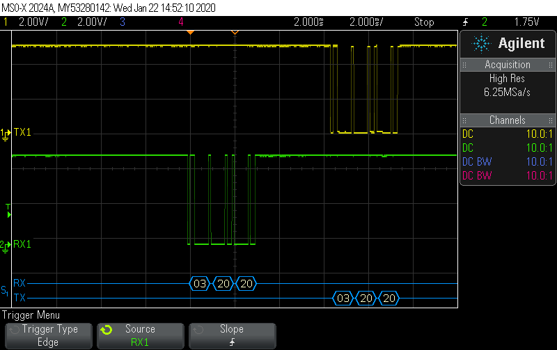
We have just received boards that have never had an application image burned to the micro. The ROM bootloader should be active, and searching for communications on UART0. We have tried communicating at different baud rates (460.8kbps, 115.2kbps, and 9600bps) all at N81. The first packet that we are sending is the COMMAND_PING packet ( 0x03 0x20 0x20 ) to UART0, but we never receive an acknowledgement. We have validated communications on an oscilloscope, and can send captures if needed.

Is there any setup steps that we are missing? Since this is the default state of the micro, I don't know what else there would be for setup instructions. We are trying to utilize the ROM UART bootloader to install the application from our board manufacturer, and then we will call the ROM bootloader to update our application from that point forward.

COMMAND_PING
  • I assume this is a new custom board. You have verified that you receive proper UART signals on pin 33, PA0? Do you have a JTAG connector on this board? Have you been able to verify that the power is good and reset (pin 70) is high?

  • Hello Bob,

    This is a custom board. I have another board that I have been debugging with that uses UART0, and I know it is functioning. On the 'blank' board, I have validated the data getting to pin 33. We have a JTAG connector, but I am not using the JTAG on the 'blank' board (since we're working out of ROM). Power and reset are both good at 3.3V.

    Regards,

    Bryan

  • Bob,

    I have used UniFlash to read the memory content of the first two addresses in memory, and all of the memory is 0xFFFF FFFF.

    Bryan

  • Very interesting. That tells me the part is working and is blank. Just to split the problem between hardware and the bootloader firmware, can you program the serial bootloader that is found in TivaWare: C:\ti\TivaWare_C_Series-2.2.0.274\examples\boards\ek-tm4c1294xl\boot_serial\ccs\Debug\boot_serial.out into the part using UniFlash. Then try the sending the ping command again.

  • Hey Bob,

    I have a different version if Tiva ware, but I flashed the application found below to my board. I am still unable to get a response to the 0x03 0x20 0x20 ping packet.

    C:\ti\TivaWare_C_Series-2.1.4.178\examples\boards\dk-tm4c129x\boot_demo_uart

    Regards,

    Bryan

  • No, that is not the right demo. (Sorry, I used a pre-release version of TivaWare) Try flashing:

    C:\ti\TivaWare_C_Series-2.1.4.178\examples\boards\ek-tm4c1294xl\boot_serial\ccs\Debug\boot_serial.out

  • Bob,

    Under C:\ti\TivaWare_C_Series-2.1.4.178\examples\boards, I only have options for:

    1. dk-tm4c129x

    2. dk-tm4c129x-boost-dlp7970abp

    3. dk-tm4c129x-em-trf7970atb

    I found nothing under a search for 'boot_serial'.

    Bryan

  • You do not have the full TivaWare library. I suggest you re-download it. http://www.ti.com/tool/SW-TM4C

    In the meantime, here is the .bin file./cfs-file/__key/communityserver-discussions-components-files/908/boot_5F00_serial.bin

  • Hello Bob,

    I flashed the binary you sent in your reply above. To confirm the flash, address 0x00 is set to 0x20000670 and address 0x04 is set to 0x00000355.

    I am still not receiving a reply to the packet of 0x03 0x20 0x20. I am sending the packet at 9600bps with no parity, eight bits, one stop bit.

    Regards,

    Bryan

  • Hello,


    Bryan Radke said:
    we are sending the COMMAND_PING packet ( 0x03 0x20 0x20 ) to UART0, but we never receive an acknowledgement.

    My group does not employ the '129 family devices ... however the following method has, "Established UART commo" (when previously there was none) on several (other maker) ARM MCUs.

    We've found that external "Pull-Up resistors" - ideally upon (both) UART_RX & (especially) UART_TX have enabled, "Bi-Directional communications!"     (My small group has no insight into the configuration & component population of your board.)   

    Should this recommendation fail - 'Scope-Caps' revealing the state (& activity) of (both) UART_RX & UART_TX would prove helpful.   And of course - there must be a proper ground (recently checked/confirmed) between your "Target MCU" and the "Programming Source."    (that's not been mentioned...)

  • CAPTURES BELOW ARE INCORRECT. SEE COMMENT BELOW FOR CORRECT CAPTURES!

    Scope traces added below. We have proper grounding to our programming source.


  • Another thing I should mention, we are using a 16MHz external clock, and I believe the standard clock is 25MHz. We are updating a product that was using a Stellaris part to now use the Tiva part. Our old design used the 16MHz clock, so we just pulled that forward.

  • Hello & thank you,

    Now we note that "RX1" sits at ground - on many/most (perhaps all) of those caps.

    It is expected that (any) UART_RX should, "IDLE at a logic high - so that the Start Bit (which drives low) may be detected!"

    As "TX1" reflects your "Programming Device's Transmit" - should not "RX1" represent your programming device's Receive?    (which has been noted as, "Silent!")

  • Thank you for your quick replies! Yes, our TX label is in regards to our programming device. I apologize, I took the capture at the wrong pins. I will update the captures and include a snapshot of our circuitry.

    Regards,

    Bryan

  • Corrected captures are added below. I have also include a capture of our hardware design. The device we typically interface with requires an inversion of the UART signal from the micro. Our Boot Load signal is only driven when programming the micro. Please let me know if you need anything else explained in detail.

  • Hi again,

    New & corrected data proves helpful - thank you.    We note that U0_TX includes NO Pull-Up resistor - which we've earlier reported as proving 'helpful' (and sometimes, mandatory!)

    Perhaps I missed this - but does the (new) RX1 label - reflect the Scope's (real) attachment to MCU pin 34?    (U0_TX)

    You surely noted that this (thus far AWOL signal) is 'gated - and or flipped' (perhaps unsuccessfully) by U2B.    Has this been checked?    (Probing At MCU (p34) or U3 (p2) ISOLATES upon the MCU's Output - which is what you seek!    

    Again - neither my staff nor I employ the '129 family - yet we recall that (often) certain GPIO pins must be driven to fully activate the boot-loader - prior to the introduction of the serial commands & data.   Are you in full/proper compliance w/this MCU demand?

    We are (about) "Out of bullets" at this juncture...

  • To help clarify, the TX label in my captures were taken from U4 pin 4. The RX label in my captures were taken from U3 pin 2.

  • Do look again at my (1 up) post - the absence of a pull-up upon U0_TX is suspect!

    We (both) seized at U3, pin 2 - as 'best candidate' for scope probing...   (of U0_TX)

  • You found that a pull up resistor is required even though our voltage levels are within range? That is what is confusing our development group. We are seeing the expected voltages at the UART.

  • Bryan Radke said:
    You found that a pull up resistor is required even though our voltage levels are within range?

    Having been to law & engineering school - you've changed my words - have you not?    A proper quote reveals: "we've earlier reported as proving 'helpful' (and sometimes, mandatory!)"      Such is (not) the same as "being required" - yet has succeeded (several times) and as a 'Sailor' - "Any port in a Storm!"    

    The logic levels you note (may) have arisen via "phantom sources" - and may not (conclusively) prove that UART_0's TX is fully/properly enabled...   (Logic Level is but one measure of such 'Full Functionality!')    The Risk-Reward 'cost' of a pull-up proves "hard to argue."

    If possible - the set-up & configuration of UART_0 should be probed - to confirm that it (REALLY) has been enabled to "Actively Transmit!"     (my firm employs ARM MCUs from many (as large clients properly demand) - thus are 'inexpert" w/this '129 family - the general direction we've provided is deemed sound...)

  • Sorry for the delay. The flash bootloader I sent you will not work as it assumed a 25MHz crystal and did not autobaud. I am not too worried about the level on the TM4C RX pin. Also, the TM4C TX pin is not being driven by the device yet since it is only trying to detect if a serial device is connected or not. Give me a few minutes to cook up a uart echo routine that should be able to verify your hardware. 

  • OK, here is an .out file that can be programmed into the part using UniFlash. It will configure UART0 for 9600 baud using only the PIOSC (precision internal oscillator, 16MHz). You should see a string "\033[2JEnter text: " printed out the U0TX pin. then each character received on U0RX will be re-transmitted on U0TX.

    /cfs-file/__key/communityserver-discussions-components-files/908/uart_5F00_echo_5F00_piosc.out

    Here is a .zip file that contains the CCS project. You can add this project to your CCS workspace by using the CCS feature "File" -> "Import".

    /cfs-file/__key/communityserver-discussions-components-files/908/uart_5F00_echo_5F00_piosc.zip 

  • Bob,

    The UART is functional. See captures below.

    Regards,

    Bryan

    \

  • OK, I think I am beginning to understand what is going on. Since you are using a 16MHz crystal, you need to autobaud. You first need to send 2 characters of 0x55, then wait about 8mS for the device to respond by changing the TX pin to an output and sending 0x00, 0xCC. I used the LM Flash Programmer Utility to create the proper sequence. Here is what I captured on my logic analyzer during a successful autobaud and program.

    Here is the configuration I used for LM Flash Programmer. Of course you must select the appropriate COM port for your PC.


  • Remember to erase the part before trying again. The logic analyzer capture I did above was on an erased part so it was using the ROM bootloader.

  • Thanks to vendor's Bob for such focused & 'insider' detail.

    Perhaps of note:   (Poster's most recent scope-cap (copied, below))     Signal levels shown (approaching 5V) are outside the spec of the '129 family!    (They are likely taken at/around connector J1 - with "DRV-PWR" of 5V input upon J1-1.  J1-6 - listed as "RXD, Data to DRV" is at full 5V level - such signal should not be applied to the '129 family!)    No mention was made of these "Changed Connections" w/in the latest Scope-Cap

    From a business (profit seeking) standpoint - would not that, "Level Shifting circuitry" (beneath your past scope-cap) be better located "at/around/w/in your Programming Source" - rather than (w/in each/every one) of your MCU Boards?    As the world has 'moved on' from 5V - limiting the program source I/O to 3V3 - would prove "SAFER" as well...

    Past guidance offered, "The set-up & configuration of UART_0 should be probed - to confirm that it (REALLY) has been enabled to "Actively Transmit!" succeeded in anticipating the "Improper Configuration" of UART_0  (baud-rate mismatch) - even if the pull-up (in this case) was not required.


  • Hi Bob,

    Curios why there was no question of errata ETH#03 (RBIAS) perhaps omitted on posters custom PCB. Is the ROM boot loader via UART exempt from ETH#03?

  • Because the TM4C1290NCPDT part does not have Ethernet.

  • I am testing many pieces of our new design and had the probes hooked up after our level conversion. We do in fact have 3.3V at the UART on the micro.

    Regards,

    Bryan

  • Sending the 0x55 twice resolved the problem. I did not see this mentioned in the ROM users guide. I would suggest clarifying the auto baud in the users guide for future use.

    Regards,

    Bryan

  • So it's in the Other MCU's forum too. Like your logic tantalizer printed hex code headers.