This thread has been locked.

If you have a related question, please click the "Ask a related question" button in the top right corner. The newly created question will be automatically linked to this question.

TM4C129XNCZAD: CAN_BUS Tx Interrupt dropped and frame not sent

Part Number: TM4C129XNCZAD

I am working on Tiva TM4C1290NCZAD Microcontroller.
I send CAN messages with 4 bytes data in every 5ms and receive with same interval from other device.
My problem is that some transmitted frames are missed occasionally and it's TX CAN interrupt is missing occasionally (The TX CAN interrupt is generated after the completion of transmission).

Does TM4C controllers guarantee CAN TX interrupt all time?

Regards,

Muhammad Hanafy

  • Dears,

    This is my working environment, and sample code attached(it is based on your example at TivaWare_C_Series-2.1.4.178).

    CCS            : Version: 9.3.0.00012

    XDCTool        : xdctools_3_32_01_22_core

    ARM Compiler   : ti-cgt-arm_18.12.5.LTS

    TIRTOS         : tirtos_tivac_2_16_01_14

    Tm4C129XNCZAD_CAN_Missed_Tx_Interrupt.c
    //*****************************************************************************
    //
    // grlib_demo.c - Demonstration of the TivaWare Graphics Library.
    //
    // Copyright (c) 2013-2017 Texas Instruments Incorporated.  All rights reserved.
    // Software License Agreement
    // 
    // Texas Instruments (TI) is supplying this software for use solely and
    // exclusively on TI's microcontroller products. The software is owned by
    // TI and/or its suppliers, and is protected under applicable copyright
    // laws. You may not combine this software with "viral" open-source
    // software in order to form a larger program.
    // 
    // THIS SOFTWARE IS PROVIDED "AS IS" AND WITH ALL FAULTS.
    // NO WARRANTIES, WHETHER EXPRESS, IMPLIED OR STATUTORY, INCLUDING, BUT
    // NOT LIMITED TO, IMPLIED WARRANTIES OF MERCHANTABILITY AND FITNESS FOR
    // A PARTICULAR PURPOSE APPLY TO THIS SOFTWARE. TI SHALL NOT, UNDER ANY
    // CIRCUMSTANCES, BE LIABLE FOR SPECIAL, INCIDENTAL, OR CONSEQUENTIAL
    // DAMAGES, FOR ANY REASON WHATSOEVER.
    // 
    // This is part of revision 2.1.4.178 of the DK-TM4C129X Firmware Package.
    //
    //*****************************************************************************
    
    #include <stdbool.h>
    #include <stdint.h>
    #include "drivers/STD_TYPE.h"
    #include "inc/hw_types.h"
    #include "driverlib/rom.h"
    #include "driverlib/rom_map.h"
    #include "driverlib/sysctl.h"
    #include "driverlib/udma.h"
    #include "grlib/grlib.h"
    #include "grlib/widget.h"
    #include "grlib/canvas.h"
    #include "grlib/checkbox.h"
    #include "grlib/container.h"
    #include "grlib/pushbutton.h"
    #include "grlib/radiobutton.h"
    #include "grlib/slider.h"
    #include "utils/ustdlib.h"
    #include "utils/sine.h"
    #include "drivers/frame.h"
    #include "drivers/kentec320x240x16_ssd2119.h"
    #include "drivers/pinout.h"
    #include "drivers/sound.h"
    #include "images.h"
    #include "drivers/touch.h"
    #include <stdbool.h>
    #include <stdint.h>
    #include "inc/hw_can.h"
    #include "inc/hw_ints.h"
    #include "inc/hw_memmap.h"
    #include "driverlib/can.h"
    #include "driverlib/gpio.h"
    #include "driverlib/interrupt.h"
    #include "driverlib/pin_map.h"
    #include "driverlib/sysctl.h"
    #include "driverlib/uart.h"
    #include "utils/uartstdio.h"
    //*****************************************************************************
    //
    //! \addtogroup example_list
    //! <h1>Graphics Library Demonstration (grlib_demo)</h1>
    //!
    //! This application provides a demonstration of the capabilities of the
    //! TivaWare Graphics Library.  A series of panels show different features of
    //! the library.  For each panel, the bottom provides a forward and back button
    //! (when appropriate), along with a brief description of the contents of the
    //! panel.
    //!
    //! The first panel provides some introductory text and basic instructions for
    //! operation of the application.
    //!
    //! The second panel shows the available drawing primitives: lines, circles,
    //! rectangles, strings, and images.
    //!
    //! The third panel shows the canvas widget, which provides a general drawing
    //! surface within the widget hierarchy.  A text, image, and application-drawn
    //! canvas are displayed.
    //!
    //! The fourth panel shows the check box widget, which provides a means of
    //! toggling the state of an item.  Three check boxes are provided, with each
    //! having a red ``LED'' to the right.  The state of the LED tracks the state
    //! of the check box via an application callback.
    //!
    //! The fifth panel shows the container widget, which provides a grouping
    //! construct typically used for radio buttons.  Containers with a title, a
    //! centered title, and no title are displayed.
    //!
    //! The sixth panel shows the push button widget.  Two rows of push buttons
    //! are provided; the appearance of each row is the same but the top row
    //! does not utilize auto-repeat while the bottom row does. Each push button
    //! has a red ``LED'' beneath it, which is toggled via an application callback
    //! each time the push button is pressed. While holding down any of
    //! auto-repeat buttons, the ``LED'' for that button should be toggled as long
    //! as the button is being held down.
    //!
    //! The seventh panel shows the radio button widget.  Two groups of radio
    //! buttons are displayed, the first using text and the second using images for
    //! the selection value.  Each radio button has a red ``LED'' to its right,
    //! which tracks the selection state of the radio buttons via an application
    //! callback.  Only one radio button from each group can be selected at a time,
    //! though the radio buttons in each group operate independently.
    //!
    //! The eighth and final panel shows the slider widget.  Six sliders
    //! constructed using the various supported style options are shown.  The
    //! slider value callback is used to update two widgets to reflect the values
    //! reported by sliders.  A canvas widget near the top right of the display
    //! tracks the value of the red and green image-based slider to its left and
    //! the text of the grey slider on the left side of the panel is update to show
    //! its own value.  The slider on the right is configured as an indicator
    //! which tracks the state of the upper slider and ignores user input.
    //
    //*****************************************************************************
     
    volatile uint32_t ui32SysClock;
    volatile INT32U u32Frequency;
     
    /*
    ********************************************************************************************************************
    ************************************************************************************************************************
    *                                              G L O B A L   V A R I A B L E S
    ************************************************************************************************************************
    ********************************************************************************************************************
    */
     
    /*
    ********************************************************************************************************************
    ************************************************************************************************************************
    *                                             G L O B A L   F U N C T I O N S
    ************************************************************************************************************************
    ********************************************************************************************************************
    */    
    //*****************************************************************************
    //
    // A simple demonstration of the features of the TivaWare Graphics Library.
    //
    //*****************************************************************************
    volatile uint32_t g_ui32MsgCount = 0;
    
    //*****************************************************************************
    //
    // A flag to indicate that some transmission error occurred.
    //
    //*****************************************************************************
    volatile bool g_bErrFlag = 0;
    
    //*****************************************************************************
    //
    // A counter that keeps track of the number of times the RX interrupt has
    // occurred, which should match the number of messages that were received.
    //
    //*****************************************************************************
    volatile uint32_t g_ui32RxMsgCount = 0;
    
    volatile uint32_t g_ui32LastRxMsg = 0;
    
    volatile uint32_t g_ui32LostRxMsg = 0;
    
    volatile uint32_t g_ui32DelayCounter = 0;
    //*****************************************************************************
    //
    // A flag for the interrupt handler to indicate that a message was received.
    //
    //*****************************************************************************
    volatile bool g_bRXFlag = 0;
    volatile bool g_bTxFlag = 1;
    //*****************************************************************************
    //
    // This function provides a 1 second delay using a simple polling method.
    //
    //*****************************************************************************
    void
    SimpleDelay(void)
    {
        //
        // Delay cycles for 0.5 Mill-second
        //
        SysCtlDelay(20000);
    }
    
    //*****************************************************************************
    //
    // This function is the interrupt handler for the CAN peripheral.  It checks
    // for the cause of the interrupt, and maintains a count of all messages that
    // have been transmitted.
    //
    //*****************************************************************************
    void
    CANIntHandler(void)
    {
        uint32_t ui32Status;
    
        //
        // Read the CAN interrupt status to find the cause of the interrupt
        //
        ui32Status = CANIntStatus(CAN1_BASE, CAN_INT_STS_CAUSE);
    
        CANIntClear(CAN1_BASE, ui32Status);
        //
        // If the cause is a controller status interrupt, then get the status
        //
        if(ui32Status == CAN_INT_INTID_STATUS)
        {
            //
            // Read the controller status.  This will return a field of status
            // error bits that can indicate various errors.  Error processing
            // is not done in this example for simplicity.  Refer to the
            // API documentation for details about the error status bits.
            // The act of reading this status will clear the interrupt.  If the
            // CAN peripheral is not connected to a CAN bus with other CAN devices
            // present, then errors will occur and will be indicated in the
            // controller status.
            //
            ui32Status = CANStatusGet(CAN1_BASE, CAN_STS_CONTROL);
    
            //
            // Set a flag to indicate some errors may have occurred.
            //
            g_bErrFlag = 1;
        }
    
        //
        // Check if the cause is message object 1, which what we are using for
        // sending messages.
        //
        else if(ui32Status == 1)
        {
            //
            // Getting to this point means that the TX interrupt occurred on
            // message object 1, and the message TX is complete.  Clear the
            // message object interrupt.
            //
            CANIntClear(CAN1_BASE, 1);
    
            //
            // Increment a counter to keep track of how many messages have been
            // sent.  In a real application this could be used to set flags to
            // indicate when a message is sent.
            //
            g_ui32MsgCount++;
    
            g_bTxFlag = 1;
            //
            // Since the message was sent, clear any error flags.
            //
            g_bErrFlag = 0;
        }
        //
        // Check if the cause is message object 1, which what we are using for
        // receiving messages.
        //
        else if(ui32Status == 2)
        {
            //
            // Getting to this point means that the RX interrupt occurred on
            // message object 1, and the message reception is complete.  Clear the
            // message object interrupt.
            //
            CANIntClear(CAN1_BASE, 2);
    
            //
            // Increment a counter to keep track of how many messages have been
            // received.  In a real application this could be used to set flags to
            // indicate when a message is received.
            //
            g_ui32RxMsgCount++;
    
            //
            // Set flag to indicate received message is pending.
            //
            g_bRXFlag = 1;
    
            //
            // Since a message was received, clear any error flags.
            //
            g_bErrFlag = 0;
        }
        //
        // Otherwise, something unexpected caused the interrupt.  This should
        // never happen.
        //
        else
        {
            //
            // Spurious interrupt handling can go here.
            //
        }
    }
    INT32S main(void)
    {
        tCANMsgObject sCANMessage, sRxCANMessage;
        uint32_t ui32MsgData;
        uint8_t *pui8MsgData;
        uint8_t pui8RxMsgData[8];
        BOOLEAN bFirstRx = STD_TRUE;
        //
        // Run from the PLL at 120 MHz.
        //
    
        ui32SysClock = MAP_SysCtlClockFreqSet((SYSCTL_XTAL_25MHZ |\
                                               SYSCTL_OSC_MAIN | SYSCTL_USE_PLL |\
                                               SYSCTL_CFG_VCO_480), 120000000);
    #if defined (USE_DSM)
        DSM_vStart();
    #endif
    #if defined (USE_PORT)
        PORT_vStart();
    #endif
        //VERBOSE_vInit();


        pui8MsgData = (uint8_t *)&ui32MsgData;
    
    
        MAP_SysCtlPeripheralEnable(SYSCTL_PERIPH_GPIOA);
        MAP_SysCtlPeripheralEnable(SYSCTL_PERIPH_GPIOB);
        MAP_SysCtlPeripheralEnable(SYSCTL_PERIPH_GPIOC);
        MAP_SysCtlPeripheralEnable(SYSCTL_PERIPH_GPIOD);
        MAP_SysCtlPeripheralEnable(SYSCTL_PERIPH_GPIOE);
        MAP_SysCtlPeripheralEnable(SYSCTL_PERIPH_GPIOF);
        MAP_SysCtlPeripheralEnable(SYSCTL_PERIPH_GPIOG);
        MAP_SysCtlPeripheralEnable(SYSCTL_PERIPH_GPIOH);
        MAP_SysCtlPeripheralEnable(SYSCTL_PERIPH_GPIOJ);
        MAP_SysCtlPeripheralEnable(SYSCTL_PERIPH_GPIOK);
        MAP_SysCtlPeripheralEnable(SYSCTL_PERIPH_GPIOL);
        MAP_SysCtlPeripheralEnable(SYSCTL_PERIPH_GPIOM);
        MAP_SysCtlPeripheralEnable(SYSCTL_PERIPH_GPION);
        MAP_SysCtlPeripheralEnable(SYSCTL_PERIPH_GPIOP);
        MAP_SysCtlPeripheralEnable(SYSCTL_PERIPH_GPIOQ);
        MAP_SysCtlPeripheralEnable(SYSCTL_PERIPH_GPIOR);
        MAP_SysCtlPeripheralEnable(SYSCTL_PERIPH_GPIOS);
        MAP_SysCtlPeripheralEnable(SYSCTL_PERIPH_GPIOT);
    
        MAP_GPIOPinConfigure(GPIO_PT2_CAN1RX);           /* Enable pin PT2 for CAN1 CAN1RX */
        MAP_GPIOPinTypeCAN(GPIO_PORTT_BASE, GPIO_PIN_2);
        MAP_GPIOPinConfigure(GPIO_PT3_CAN1TX);           /* Enable pin PT3 for CAN1 CAN1TX */
        MAP_GPIOPinTypeCAN(GPIO_PORTT_BASE, GPIO_PIN_3);
        /*
         * The GPIO port and pins have been set up for CAN.  The CAN peripheral must be enabled.
         */
        SysCtlPeripheralEnable(SYSCTL_PERIPH_CAN1);
        CANInit(CAN1_BASE);        /* Initialize the CAN 1 controller */
    
    
        u32Frequency = CANBitRateSet(CAN1_BASE, 120000000, 125000);
    
    
        //CANIntRegister(CAN1_BASE, CANIntHandler); // if using dynamic vectors
        //
        CANIntEnable(CAN1_BASE, CAN_INT_MASTER | CAN_INT_ERROR | CAN_INT_STATUS);
    
        //
        // Enable the CAN interrupt on the processor (NVIC).
        //
        IntEnable(INT_CAN1);
    
    
        //PORT_srmSetupCAN1ISR(CANIntHandler, STD_TRUE);


        //
        // Enable the CAN for operation.
        //
        CANEnable(CAN1_BASE);
    
        CANRetrySet(CAN1_BASE, 0);
        //
        // Initialize the message object that will be used for sending CAN
        // messages.  The message will be 4 bytes that will contain an incrementing
        // value.  Initially it will be set to 0.
        //
        ui32MsgData = 0;
        sCANMessage.ui32MsgID = 1;
        sCANMessage.ui32MsgIDMask = 0;
        sCANMessage.ui32Flags = MSG_OBJ_TX_INT_ENABLE;
        sCANMessage.ui32MsgLen = sizeof(pui8MsgData);
        sCANMessage.pui8MsgData = pui8MsgData;
    
        sRxCANMessage.ui32MsgID = 0;
        sRxCANMessage.ui32MsgIDMask = 0;
        sRxCANMessage.ui32Flags = MSG_OBJ_RX_INT_ENABLE | MSG_OBJ_USE_ID_FILTER;
        sRxCANMessage.ui32MsgLen = 8;
    
        //
        // Now load the message object into the CAN peripheral.  Once loaded the
        // CAN will receive any message on the bus, and an interrupt will occur.
        // Use message object 1 for receiving messages (this is not the same as
        // the CAN ID which can be any value in this example).
        //
        CANMessageSet(CAN1_BASE, 2, &sRxCANMessage, MSG_OBJ_TYPE_RX);
    
        //
        // Enter loop to send messages.  A new message will be sent once per
        // second.  The 4 bytes of message content will be treated as an uint32_t
        // and incremented by one each time.
        //
        g_ui32DelayCounter = 5000;
        while(g_ui32DelayCounter > 0)
        {
            g_ui32DelayCounter--;
            SimpleDelay();
        }
        while(1)
        {
    			g_bTxFlag = 1; 
            if(g_bTxFlag == 1)
            {
                g_bTxFlag = 0;
                //
                // Print a message to the console showing the message count and the
                // contents of the message being sent.
                //
    			//if((ui32MsgData - g_ui32MsgCount) > 0U)
    			//{
    			//	VERBOSE_printf(RED_TEXT);
    			//}
    			//VERBOSE_printf("\nTx:%d, Loss:%d", ui32MsgData, (ui32MsgData - g_ui32MsgCount));
    			//VERBOSE_printf(WHITE_TEXT);
                //
                // Send the CAN message using object number 1 (not the same thing as
                // CAN ID, which is also 1 in this example).  This function will cause
                // the message to be transmitted right away.
                //
                sCANMessage.ui32Flags = MSG_OBJ_TX_INT_ENABLE;
                CANMessageSet(CAN1_BASE, 1, &sCANMessage, MSG_OBJ_TYPE_TX);
    
    
                //
                // Now wait 20 mill-second before continuing
                //
                //SimpleDelay();
    
    
                //
                // Increment the value in the message data.
                //
                ui32MsgData++;
            }
            //
            // If the flag is set, that means that the RX interrupt occurred and
            // there is a message ready to be read from the CAN
            //
    
            while(g_ui32DelayCounter > 0)
            {
                g_ui32DelayCounter--;
                if(g_bRXFlag)
                {
                    //
                    // Reuse the same message object that was used earlier to configure
                    // the CAN for receiving messages.  A buffer for storing the
                    // received data must also be provided, so set the buffer pointer
                    // within the message object.
                    //
                    sRxCANMessage.pui8MsgData = pui8RxMsgData;
    
                    //
                    // Read the message from the CAN.  Message object number 1 is used
                    // (which is not the same thing as CAN ID).  The interrupt clearing
                    // flag is not set because this interrupt was already cleared in
                    // the interrupt handler.
                    //
                    CANMessageGet(CAN1_BASE, 2, &sRxCANMessage, 0);
    
                    //
                    // Clear the pending message flag so that the interrupt handler can
                    // set it again when the next message arrives.
                    //
                    g_bRXFlag = 0;
    
                    //
                    // Check to see if there is an indication that some messages were
                    // lost.
                    //
    
                    sRxCANMessage.ui32Flags = MSG_OBJ_RX_INT_ENABLE | MSG_OBJ_USE_ID_FILTER;
                    if(sRxCANMessage.ui32Flags & MSG_OBJ_DATA_LOST)
                    {
    
                    }
                    if((*(INT32U *)pui8RxMsgData > (INT32U)(g_ui32LastRxMsg + 1U)) && (bFirstRx == STD_FALSE))
                    {
                        //VERBOSE_printf(RED_TEXT);
                        g_ui32LostRxMsg += *(INT32U *)pui8RxMsgData - (g_ui32LastRxMsg + 1U);
                    }
                    //VERBOSE_printf("\nRx:%d, Exp: %d, T Rx:%d, Los:%d",\
                                   *(INT32U *)pui8RxMsgData, (g_ui32LastRxMsg + 1U), g_ui32RxMsgCount, g_ui32LostRxMsg);
                    //VERBOSE_printf(WHITE_TEXT);
                    g_ui32LastRxMsg = *(INT32U *)pui8RxMsgData;
                    bFirstRx = STD_FALSE;
                }
                SimpleDelay();
            }
            g_ui32DelayCounter = 9;
        }
    }
    

  • How much traffic is on your CAN bus? If there is higher priority traffic on the CAN bus, your message will not be transmitted until it is the highest priority message. This could mean it takes more than 5mS before the message actually transmits. Using a logic analyzer or CAN bus protocol analyzer will help you understand what is going on with the CAN bus. 

  • Hello Bob,
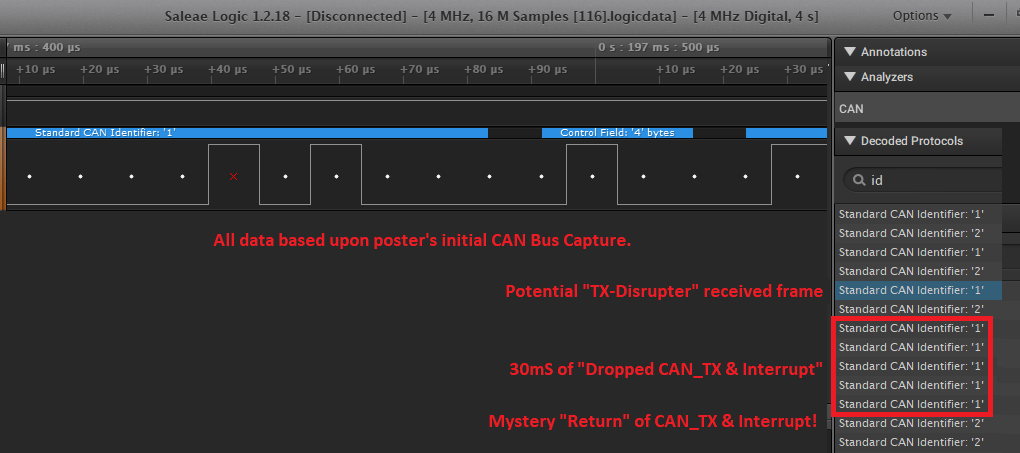
    Thanks for our appreciated fast reply. My CAN bus has high traffic already and two missing Transmitted frames are not sent even  30 ms wait and the following third frame of them was sent successfully. I checked this condition when sending from device with ID:2 to device with ID:1 and the last transmitted frame from device:2 was 0x46 0x00 0x00 0x00(length 4) and then two frames were missed till 30 msec receiving from device:1 and then device:2 sent 0x49 0x00 0x00 0x00. I checked brevious case from the device:1 and also using logic analyzer at time 0.1966635s for last frame fdrom device:2 and then two missed frames and then sent frame from device:2 at time 0.2264265( attached logic analyzer saved capture from Saleae logic 1.2.18)4 MHz, 16 M Samples [116].zip

  • You are overwriting your transmit message when the previous message did not yet transmit. I think you need to move line 409 (g_bTxFlag = 1;) to before the while(1); statement. That way you will only send a new message after you have successfully sent the previous message. You may not get a message every 5mS because of bus traffic, but at least you won't drop messages.

  • Hello Bob, 
    I already tried this concept of waiting forever for the Tx interrupt flag BUT when sending the 54th frame the transmitted frame is lost and no Tx interrupt happens and I CAN NOT send again as infinite waiting for missed flag at time 2.82912575 s in the attached logic analyzer capture


    Thanks and regards

    Muhammad Hanafy

    4 MHz, 16 M Samples [119].zip


  • Are you getting the g_bErrFlag set? If so, what is the value returned by CANStatusGet()? 

  • Hello Bob, 
    When I'm trying to transmit frames 0x356 (decimal: 854) as it appears at( line 139 file CAN_Missed_TX_FRAME_Interrupt.txt) and at ( time 6.32203525 s at capture logic analyzer file 8 MHz, 128 M Samples [138].logicdata)  it is transmitted successfully without error BUT when trying transmission of next frame 0x357(decimal: 855) as it appears at( line 177 file CAN_Missed_TX_FRAME_Interrupt.txt) it WAS NOT transmitted over CAN bus and no TX interrupt occurred, although there was no error returned by CANStatusGet().

    Thanks and regards

    Muhammad Hanafy

    Attached Node1 & Node2 projects and log file and logic analyzer capture.

    Project_And_Logs.zip

  • Bob,

    I'm Mohammed's Collage, and i wish if you can help us in this topic because we have a product line which is delayed because we can't deliver while keep losing frames over the CANBus for unknown reason.

    Any help will be appreciated!

    Thanks,

    Mohammed Fawzy

  • I don't have the same hardware as you. Using my hardware and my software, I created a similar situation. I transmit a CAN frame. When I get a CAN TX interrupt of a successful transmission, I set a flag. The main code loops looking for the flag to be set. When it is set, it clears the flag, increments the count and starts the next transmission. So far I have over 33 million successful CAN frames transmitted. I cannot debug your system for you, but it does not look like a device issue.

  • Hello Bob,

    Our group has followed this thread w/interest - and appreciate the time & effort invested by both parties.

    We've two questions - perhaps shared by this poster - springing from the CAN Frame Mechanism you've devised:

    • Does "your hardware & software" include the 2nd CAN node - as (we believe) the poster employs?
    • If not - might (something) - introduced via that 2nd CAN node "disturb" (thus prevent) poster's CAN_TX Interrupt?

    He has noted, "High CAN Bus traffic" - yet the success-rate of the CAN_TX Interrupt is high - might any "patterns" be noted at/around those "missing interrupts?"

    The issue has thus far been "framed" as entirely "MCU caused" - yet could not (other) external issues, "cause and/or contribute?"

    • power variance issue
    • noise sources
    • RF infiltration
    • special "timing coincidences/overlaps" - between the nodes 

    In addition - even though this issue has "delayed critical shipments" - I don't recall adequate detailing of the:

    • distance between each CAN node
    • method of interconnect joining the nodes

    In certain of our firm's defense applications - we've found that "tightly twisted-pair" cable "succeeds" - where 'all other' interconnect implementations fail...   (this proves true for cable lengths of 3 meters & beyond)   Should a "solution" be sought - such detail should be provided.

    Would it not prove useful to try to "capture" the "constellation of conditions" which may independently (or in concert) lead to this "failed interrupt?"     My group is not, "Claiming that the MCU" is "Blameless" - instead we are recognizing the (potential) negative impact - introduced by the outside (ever connected) world...

  • There is one problem with this code, how severe it is I don't remember but it could cause the problem you are seeing in some vendors implementations of communications peripherals.

    You only read the the interrupt status a single time in the interrupt routine using

        //
        // Read the CAN interrupt status to find the cause of the interrupt
        //
        ui32Status = CANIntStatus(CAN1_BASE, CAN_INT_STS_CAUSE);

    The potential issue is that if there is a second pending interrupt then it may be lost, so if both interrupt status 1 and 2 are valid you may only get a single interrupt. As I read the documentation that should not happen but it's not something you should depend upon, especially in a high message frequency situation.

    Another item in your source that jumped out is that you do nothing in the case of a "spurious" interrupt, you don't even note it. So there is a possible source you don't catch and it's one that could potentially have you in an infinite interrupt loop.

    These are basic steps to take to increase robustness although I'm not convinced either is definitely the source of your problem. They may be essential to finding your problem though.

    One additional point. Bob asked whether the g_bErrFlag was set. You didn't really answer that question but answered a different related question that implied without stating that it wasn't set. I think it's important to be precise in answering that question. Is g_bErrFlag set?

    Robert

  • Greetings Robert,

    I'm (almost) in agreement - you wrote:

    "You only read the the interrupt status a single time in the interrupt routine using

         // Read the CAN interrupt status to find the cause of the interrupt
        //
        ui32Status = CANIntStatus(CAN1_BASE, CAN_INT_STS_CAUSE);

    The potential issue is that if there is a second pending interrupt then it may be lost!"

    That's an (almost) inspired find - yet performing (multiple) such reads costs time & (may) be "Unnecessary!"

    Proposed instead: "Change the "CANIntStatus()" parameter from "CAN_INT_STS_CAUSE" to "CAN_INT_STS_OBJECT."

    The "SW-TM4C-DRL-User Guide" notes:

    "CAN_INT_STS_OBJECT returns a bit mask indicating which message objects have pending interrupts.   This value can be used to discover all of the pending interrupts at once,  as opposed to repeatedly reading the interrupt register by using CAN_INT_STS_CAUSE."

    Time (likely now) for a Green Stamp (i.e. this Resolved) ideally shared between poster Robert & my team.   (Vendor Bob's sw 'solution' was not revealed - hard to reward ...)

    The "rarity" of this occurrence (still) concerns - my recent posting of "Non-MCU" causes - attempts to answer there as well..

  • Good points cb1, and definitely your proposals should be looked at as well. I only meant to supplement. I'd actually probably perform both reads multiple times (robustness before optimization, you can remove unnecessary checks after you shown them to be so)

    There's a few other things we don't know that may have an effect.

    • What else is on the bus
    • That no other devices use the same IDs to transmit (basic, but still should be confirmed)
    • Whether the 'missing' packet is received.

    Robert

  • CB1,

    I have not yet added the additional CAN traffic. That will be my next step. Unfortunately I have another thread concerning the CAN FIFO example that I need to work on first. by the way, my first test is over 444 million transfers without stopping.

  • Bob,

    You have clearly gone, "Above/Beyond" w/this poster.   (now posters)

    Outsiders Robert & cb1 crüe attempt to, "Inform & Advise" - as & when able.

    High volume, CAN Bus Traffic - has disrupted communication at multiple of our (large) clients.    Almost always - reduction in that "Traffic Level" produced "Notable Improvement."

    Robert & I have identified multiple, "Usual Suspects" - although my post yesterday (appears) to be the first to, "Seriously question" the impact of "Outside Agents" (i.e. Noise, RF, marginal circuit path, etc.) to prove disruptive.

    Indeed your addition of that 2nd CAN node better approximates our poster's application.    However - the (temporary) disabling of that 2nd node - BY THE POSTER - proves a, "rather obvious, eased & (perhaps) critical" Next Step!

  •  to be on the page, we have 1MB of code in the project (large project), and we spent time to create two samples that demonstrate the reported problem using two nodes. so what you are trying to do is out of the problem scope. such that the problem is happening when two nodes are trying to send with high frequency to each other, an interrupt for the transmitted frame will be dropped.

    Please note that if i left the setup with one node is transmitting, the interrupt won't be lost, so definitely, the problem is caused by using two nodes not one node.

    Anyway, any help in the scope of the problem will be appreciated!

     &  Thank you guys for your great help trials especially when the advises comes from great practical experience in the reported problems !

    Actually, i don't understand how the suggested solution 

    "Change the "CANIntStatus()" parameter from "CAN_INT_STS_CAUSE" to "CAN_INT_STS_OBJECT."

    can solve the problem?? . such that if we didn't read the CAN_INT_STS_CAUSE and we got interrupt CAN_INT_INTID_STATUS, we will keep enter the ISR due to CAN_INT_INTID_STATUS for ever. and if we didn't enable  CAN_INT_STATUS in the below line

    CANIntEnable(CAN1_BASE, CAN_INT_MASTER | CAN_INT_ERROR | CAN_INT_STATUS);

    and left the CAN_INT_MASTER | CAN_INT_ERROR, we won't interrupted at all even if the bus is OFF (this raise another question, why there is no interrupt occurred even  CAN_INT_ERROR  is enabled when the CANbus is OFF?)

    So please advise if i missed anything!

    Best Regards


  • Mohammed Fawzy said:

    Actually, i don't understand how the suggested solution 

    "Change the "CANIntStatus()" parameter from "CAN_INT_STS_CAUSE" to "CAN_INT_STS_OBJECT."

    That was not the suggestion.

    The suggestion was to re-read the interrupt status within the interrupt until it was clear.

    Mohammed Fawzy said:
    such that if we didn't read the CAN_INT_STS_CAUSE and we got interrupt CAN_INT_INTID_STATUS, we will keep enter the ISR due to CAN_INT_INTID_STATUS for ever.

    You should not depend on this. You are seeing issues, this is something you need to verify works.

    One note: You do realize CAN does not guarantee message delivery? It is possible for a receiver to both miss messages and receive duplicate messages. All CAN guarantees is that the messages probably won't be corrupted and priorities will be mostly respected. CANbus's design favours repetitive delivery over guaranteed delivery, making the design assumption that late messages are as bad or worse than missing messages.

    Robert

  • One other question, what's your bus load?

    Robert

  • Greetings,

    Seven days have passed - such silence forces (extra) effort & renewed focus - neither especially welcome nor efficient.    A simple response, "Received - we are exercising/analyzing - need a few days!" - proves much superior - does it not?

    cb1_mobile said:

    The "SW-TM4C-DRL-User Guide" notes:

    "CAN_INT_STS_OBJECT returns a bit mask indicating which message objects have pending interrupts.   This value can be used to discover all of the pending interrupts at once,  as opposed to repeatedly reading the interrupt register by using CAN_INT_STS_CAUSE."

    Your argument appears w/the user guide - which was "strengthened" by the combination of (both) Robert's & my suggestions.   Note that "Changing the sequence/arrival" of (each) parameter - does not suggest either's abandonment.

    Robert's highlight of, "Message Delivery NOT Guaranteed" proves especially true when multiple nodes operate at high & (near) continuous message frequency.     However - we've further found that "Non Linear Reduction of the Message Frequency" (i.e. sometimes only a minimal reduction [<10%]) would disproportionately raise proper, "Message Receipt!"

    No response has been received to our (proper) concern re: "Other, external events" (i.e. noise etc.) impacting message receipt.    Our firm has observed - on multiple occasions - that "Missing Messages due to high bus activity" may be significantly reduced via:

    • locating each node in a (near) "clean-room" (RF suppressed) environment
    • minimizing the length of the interconnection medium
    • upgrading the quality of the interconnection medium
    • deliberate generation of "noise" - and the implementation of "noise remediation techniques" - to reduce.    In fact - we "proved" that such noise introduction, "Could cause (both) "Missed or Erroneous" Message Receipt - upon command!"   (by monitoring the CAN Bus we were able to "inject noise" during a key message - causing "Miss/Error!")

    Your "Message Delivery Success" may be impacted by such factors - "ruling them out" (as appears the case here) may not prove in your best interest...

  • Hello,

    the testing platform had been modified with no luck as the following:

    - codes for the two nodes are modified to have read CAN_INT_STS_OBJECT after reading CAN_INT_STS_CAUSE.

    - display the error which may occur over the CANbus if it happened but we didn't get any errors during the test.CAN missing TX interrupt test.zip

    - change the connection between the two nodes for half meter of twisted pair in a room with just a PC for monitoring the log and debug the code.

    - the load over the bus is nearly 100% such that we are using rate 125 Kb/s, so one frame CAN shall take 1 ms and we are sending 1 frame every 1 ms from both unit at the same time.

    Again, the problem is - so everyone can be on the same page.- we are not looking to the transmitted frame in the receiver node but the issue is that the transmitting unit is loosing the transmission interrupt for no reason and this is only appear when we have another node on the network which is trying to transmit at the same time. so we need to know why are we losing the interrupt, is it a code problem like wrong handling for the interrupt or it is microelectronic problem?

    please note that we don't think that it is a noise on the interconnection environment because we are using two nodes in the testing but we are monitoring only one unit to confirm that every time the unit is trying to send it will get the corresponding TX interrupt in the same unit

    Anyway, the latest test code is attached

    Thanks and Best Regards,

    Mohammed

  • Mohammed Fawzy said:
    - codes for the two nodes are modified to have read CAN_INT_STS_OBJECT after reading CAN_INT_STS_CAUSE.

    In a loop until none are read? The process must be

    1. Read status
    2. Clear status, including taking any needed actions
    3. Repeat until status indicates not remaining data or status available.

    Mohammed Fawzy said:
    change the connection between the two nodes for half meter of twisted pair

    Of the proper impedance? Impedance and cable wiring does matter.

    Mohammed Fawzy said:
    the load over the bus is nearly 100%

    THIS IS A PROBLEM No communication bus can deal with that load. CAN is better than Ethernet but still 100% load is simply unsustainable. I would only do that as a stress test, never as an expected operating condition.

    Robert

  • Actually i'm not looking to have such load over my network but i have a project which is send message every 10 seconds which is shall be fair enough but the problem that even with this slow rate, we lose the interrupt every few days, so to trouble shoot the problem we generated the two samples which are trying to produce the same problem but in short time and we manged to produce it.

    BTW, we are using 120ohm termination resistor, also if we reduce the bus load to 20%, the two nodes can work for two days using the test code

  • Mohammed Fawzy said:
    Actually i'm not looking to have such load over my network but i have a project which is send message every 10 seconds which is shall be fair enough but the problem that even with this slow rate, we lose the interrupt every few days, so to trouble shoot the problem we generated the two samples which are trying to produce the same problem but in short time and we manged to produce it.

    Fair enough but 75-80% would be more realistic to avoid effects just due to loading. I wouldn't assume that the problem you see at 100% load is the same you see after a few days at close to zero load. In fact that it appears (from your description) that raising the load to 20% doesn't affect the failure frequency that the effect at 100% load is probably different.

    Mohammed Fawzy said:
    BTW, we are using 120ohm termination resistor

    That good, I didn't even think to ask about termination (make sure there's only two and none of your PC or other boards have include termination). However, I was referring to the cable impedance not termination resistors.

    Robert

  • you mean that i have the same output which is losing the TX interrupt for two different problem? 

    Anyway, i'm waiting  reply to use the same samples on two nodes, i think he is expert enough to handle such environment problem and i tried to make his life easier by preparing the test code. 

  • Mohammed Fawzy said:
    you mean that i have the same output which is losing the TX interrupt for two different problem?

    Yes, Clearly, you can.

    Robert

  • Interesting - the timely arrival of poster's latest data (and clarification) - along w/poster Robert's on-going analysis - is helpful & appreciated.

    Now my small group past reported:

    cb1_mobile said:
    Robert's highlight of, "Message Delivery NOT Guaranteed" proves especially true when multiple nodes operate at high & (near) continuous message frequency.     However - we've further found that "Non Linear Reduction of the Message Frequency" (i.e. sometimes only a minimal reduction [<10%]) would disproportionately raise proper, "Message Receipt!"

    And Robert & poster (both) have essentially confirmed our report: (especially the issue's "Non-Linearity"):  "Fair enough but 75-80% would be more realistic to avoid effects just due to loading. I wouldn't assume that the problem you see at 100% load is the same you see after a few days at close to zero load. In fact that it appears (from your description) that raising the load to 20% doesn't affect the failure frequency that the effect at 100% load is probably different."

    As it appears now essentially proven & agreed that "High CAN Bus utilization raises susceptibility to error" should not the probe, "Shift to a more narrow/focused cause?"

    • First - "How is it known - or is it (even) known - that the "Failed Frame & Dropped Interrupt" were (in all manner) properly formatted, timed & presented for transmission?"    If the CAN transmission is (somehow) malformed (potentially by (any) form of electrical disturbance) is the "Proper Frame transmission & interrupt (still) guaranteed?"     Has this possibility been missed - until now?    (the "expectation" that his may prove rare - does not justify its dismissal - minus (any) real investigation!)
    • Along this same investigative trail - might the simultaneous arrival of (both) CAN_TX & CAN_RX - cause (at least contribute to) such Failed Frame & Interrupt?    As both CAN "Ends" are asynchronous - is it not possible that "at some time" - synchronization (or close to it) may occur ... w/"destructive consequences?"
    • Poster has captured the exact message (even w/in a long sequence of messages) which failed - yet there has been "NO mention" of the "Remote Message" which occurred at/around that exact message failure!    That should prove of (some) interest - should it not?    (Especially - should that "message type" cause such failure repeatedly!)    It is my group's opinion that this (notable) "Failure to display interest in - and/or properly examine" this potential "Failure Trigger Message" - demands exploration!
    • Poster just today has nicely clarified the issue's (thus far) being confined to a missing CAN_TX interrupt from one node.   While "Noise & other external events" usually will more notably disrupt the reception of remote messages - they have proven to be disruptive to the "local" CAN-based MCU, as well.   (And the presence of a PC in proximity - raises concern - PC's are "well known Offending Radiators!"
    • In our past yet "exacting CAN testing" - we systematically enforced: CAN Bus quiet periods (2-4 Sec. max) & probed & discovered the "Rate of Bus Traffic which allowed (near) 100% message reception.    
    • In addition - the regular & coordinated, "Reset of all CAN Nodes" - at intervals determined to be "sufficient yet non-harmful" - enabled the progression from 'near' to 100% message reception.

    Poster earlier wrote, "the transmitting unit is losing the transmission interrupt for no reason!"    That's a conclusion (likely) born out of frustration - and far from "scientifically or logically" correct!     "No reason yet discovered" proves far more realistic - and properly serves to motivate one to overcome, "Improper and/or Inadequate PROBING" - which the listing above properly targets.   Such "failed interrupts" have "known causes:"

    • single interrupt improperly cleared
    • multiple interrupts - one or more improperly or not cleared
    • interrupt clearance proper - yet occurred too late to be fully/properly recognized
    • and possibly (other) "interrupt disrupting" events and/or mechanisms

    It is believed that "identifying the cause of the failed interrupt" may go far to aiding/assisting "Proper Interrupt Handling" - which prevents Interrupt Loss!

    It has yet to be asked (while always required) "Has poster been able to "duplicate this issue" with an "Entirely Different Board Pair?"    If that's not been done - dreaded "Single Board Anomaly" may have "unfairly & improperly" generated the (unfortunate, non-productive) exercise & investment of (helpers' & vendor's) time & effort...   Do kindly advise - (helpers' time is of (some) value!)

    It may be that the vendor's CAN API proves susceptible (when sufficiently stressed) to such dropped interrupt - yet the methods noted above may be explored by the "Poster alone burdened w/the issue" - and these methods are logical, methodical - and have "Proved Successful!" (albeit w/another's ARM Cortex M4 MCUs) in the past...)

  • Greetings,

    It would appear that "social distancing" has propagated into this forum's space.    Can you say, "Poster Distancing?"    Note that our crüe maintains "arms length" separation from PC/mouse/keyboard.    (almost...)

    We've invested a few more hours in the attempt to resolve this, "CAN Frame & CAN_TX Interrupt Lost" challenge.   We were never fans of the '129 family' (have no chips nor boards) - & own an Agilent L.A. - not the one employed by this poster.    That said - we downloaded the poster's L.A. software - performed a "deep dive" - and gained far greater insights into, "What (may) be causing this "None too trivial" issue."   And again - we resist the impulse to claim, "No reason" - believing "No Discovered reason (yet)" - to be more reflective of reality... 

    We request that this poster "Re-Run" his original test code - without (any) changes - which led to these CAN Bus Captures.   And then - once again - provide an updated, "L.A. Capture."  (Duplicating the original "Test-Run & Capture" as much as possible!)

    4 MHz, 16 M Samples [116].zip

    Recall my group theorized that it proved, "Within the realm" that the "incoming CAN Data" - may have contributed to poster's issue.   Now both this poster (and today my group) have carefully noted "exactly where" poster's CAN Code "Breaks Down" - yielding 30mS of "CAN_TX Silence!"    We now sense that should that "Same Failure" - occur (almost) exactly as it had during poster's initial test - then that (unchanged) "Incoming CAN Data" rises high upon the "suspect list!"    (i.e. should CAN_TX again fail - at exactly the same place w/in the CAN Data Sequencing (again w/the exact operating conditions [as past] imposed) - then a clear "linkage" (may) have been discovered!   Unknown is how this poster "Started and/or Sync'ed" each of his two CAN boards/implementations...   Ideally - if both boards were properly programmed - then the, "Application of Common Power to both (simultaneously)" should create a 'reasonable' board to board sync.

    It is vital that the new test be conducted identically to the first one - which (again) produced the CAN Data captures.   (attached herein.)    In addition - it would prove useful if a systematic response to the "most recent, close proximity posts" would be (later) provided.   

    To be clear - the simple, "Duplication of poster's initial test" - and submission of a NEW Logic Analyzer Capture zip file - should be "Task # 1..."

  • Mohammed,

    I have been able to duplicate your issue and agree that it is not behaving as expected. I suspect that the nature of the CAN interface registers and the code clearing interrupts (inadvertently) in the main thread is the issue. I am still working on this one.

  • Hello Bob,

    May we ask if "your code" (for the remote CAN device) drove the bus w/an "incrementing initial data field value" - as the poster's code provided.     We ask as some irregularities appeared at/around certain ASCII bytes.

    We are unable to explain, "How or why" - poster's CAN_TX went quiet for 30mS.   (While 5 remote device CAN_RX messages were successfully received.)   Somehow - without poster intervention (i.e. humans cannot respond in such time-frame) your CAN Engine recovered, producing (proper) CAN_TX frames at the 226 & 232mS marks!

    Might you know if poster's L.A. "proves blind" to:   (by "blind" - we mean such improper bus events are NOT displayed!)

    • a disturbance (i.e. noise impulse) arriving upon the CAN bus
    • a "Malformed CAN Transmission Packet"

    We ask this as the CAN bus appears "pristine" in the absence of bus traffic.    Our Agilent unit is able to monitor the CAN bus via simultaneous digital and analog (i.e. scope-like) channels - which "nicely capture such bus disturbances" - rather than "avoiding their display..."

    Thanks your time & attention - note that your device expertise is much appreciated...   (My firm has several clients much interested in such issue...)

  • The second node is transmitting an incrementing count.

    I cannot yet explain it, but moving the call to CANMessageGet() inside of the interrupt routine seems to resolve the issue. 

  • Bob Crosby said:
    I cannot yet explain it, but moving the call to CANMessageGet() inside of the interrupt routine seems to resolve the issue. 

    Doesn't CANMessageGet clear the interrupt? That is what the documentation says. That would make calling it outside the interrupt an error. It's a race condition waiting to happen.

    Robert

  • I wish it were that straight forward, the last parameter of the CANMessageGet() function is a boolean to clear the interrupt if true. In the original posters implementation he had that parameter false, and had a specific call to CANIntClear() in the interrupt routine. I replaced the call to CANIntClear with a call to CANMessageGet() with the last parameter set to true in the interrupt routine.

  • Here - yet (one more) "fly in this delightful ointment."

    Someway, somehow - minus poster intervention (as earlier explained) this "LOST CAN_TX & Interrupt" appeared to have "Self-Restored" - and CAN_TX continued (after) "Missing two frames" - exactly as poster (earlier) reported.    Note (especially) that this "Self-Restoral" occurred w/out the "latest/greatest" software fix!    Should not this warrant (some) further analysis?

  • Thank you very much Bob,

    i'm going to change the sample with your suggestions and will run the setup for a while then i will let you know, but i did a quick look to the CANMessageGet and CANIntClear and both of them are clearing the same register  HWREG(ui32Base + CAN_O_IF2CMSK)  so why the first one shall make a difference?

    Best Regards,

    Mohammed Fawzy

  • Mohammed,

    I really don't know the root cause yet. I don't think it matters which function clears the interrupt, but rather that the CANMessageGet() function was using the IF2 registers. If an interrupt occurs between setting up one the the IF2 registers and before it does the final write to start the transfer, the interrupt routine could corrupt the other IF2 registers. Of course that does not happen when CANMessageGet() is in the interrupt routine. The only problem with this great theory is that all of the other TivaWare CAN functions used in this example use the IF1 registers. Bottom line: I don't know.

  • Thanks Bob, that does muddy the water.

    Robert

  • Should there be interest - follows a summary of our review of poster's initial CAN Bus Data Capture.

    The (thus far) unexplained, "Loss of CAN_TX" (for a 30mS duration) - followed by the "Restoral/Reappearance" of CAN_TX remains a mystery...

    ID2 is the CAN device "failing" (BRIEFLY) during its attempt to transmit.    ID1 is the (remote) CAN receiving device - yet (also) consistently transmitting (apparently) WITHOUT ISSUE!    Difficult to understand how such fact has garnered "Near Zero" interest ... but for our group's "deep dive."    Young staff's been advised - "It is the Quality of Effort - Not recognition" - which proves the "Pursuit of Excellence..."

    Time ........ ID ...... Msg .. CheckSum
    Stamp (mS) 

    156                 ID2        A2        -
    157                 ID2        B2       2821
    163                 ID1       w2       5992
    168                 ID2       C2       5629
    169                 ID1       x2       32217
    176                 ID1       y2       25377
    177                 ID2       D2      19733
    183                 ID1       z2       16425
    185                 ID2       E2       21485
    191                 ID1       {2        24273
    196                 ID2       F2       28901
    197                 ID1       I2        -
    205                 ID1       }2        -
    210                 ID1      ~2        -
    216                 ID1      123 2   -
    221                 ID1      128 2   3521   Might these 2 "strange values" have restored ID2?
    226                 ID2      I2         6740   G2, H2 "Lost" - during 30mS "RX only" interval...
    232                 ID2      J2        14684

  • Bob,

    i made the same modification and i'm getting ISR fault, can you send me the updated samples?

    Best Regards,

    Mohammed Fawzy

  • Here is the latest project that I have been using. You will need to change SW_ROOT back to SW_ROOT1 as I have a different path to the library. /cfs-file/__key/communityserver-discussions-components-files/908/Node1.zip

  • Thank you Bob,

    Currently, I have two different setup (each setup has two CAN nodes) running the samples, one setup with bus load 50% and the other 100% to see the result, just i'm doing a stress testing even my application will run with a very little bus load but the test shall speed up the detection for missing the interrupt. i will let you know by tomorrow the result but it sounds to be promising.

  • Your very first "test Results" - revealed via your L.A. scan/capture - enabled my group to discover "Highly Similar" ill effects  visited upon your "remote (ID1) side" - not (just) upon ID2 - as your test (and writing) presented.

    Your review of  "both CAN sides" - rather than just one - is likely to, "Speed, Ease even Enhance" your issue's resolution.

    In the investigation of such (likely) "MCU Race Conditions" - anything you can do to "Encourage the Failure Mode" (i.e. to be able to, ideally "Command such Failure") works overwhelmingly to your advantage!

    Our (unnoted) post yesterday (12:35) revealed certain (potential) "CAN Bus Traffic Patterns" - which may have played key roles in (both) this issue's cause ... and possible correction...

    Too limited - and non-exhaustive, less than skilled probing - for "ALL potential root causes" often leads to a "solution today" ... yet (really) "issue's masking - and return - tomorrow!"

    It should be noted that it proves "Very Hard" to devise a solution which succeeds under "ALL" possible conditions.   Such holds true - even if - and especially if - preliminary "Testing" is less than exhaustive - and (not) both thoroughly & systematically implemented & creatively monitored...

  • Bob,

    The scope of my problem was that we lose the interrupt for the some transmitted object if we have two nodes trying to send in the same time and with high rate to each other and this raised a question if we are only loosing the frame and the TX interrupt or only the TX interrupt and the answer is received using the logic analyzer that we loss both of them, so this problem is solved by using the  CANMessageGet inside the ISR instead of CANIntClear even both of the is clearing the interrupt.

    my two setups with 50% and 100% bus load were working for more than 24 hours without loosing any interrupt with millions of transmitted packets.

    so i'm not losing any interrupt but i think that we deserve a technical clarification about the actual cause of of the problem which is solved by replacing the CANMessageGet  by CANIntClear.

    Thanks and Best Regards, 

     Mohammed Fawzy

  • I am glad to hear you have a working solution. I understand and agree we should pursue this to root cause. I will spend some more time looking at it.

  • OK, I understand what is happening. As written the TivaWare CAN functions are not re-entrant. In this case, it will fail if you get a receive interrupt while the CANMessageSet() function is trying to re-enable the transmit mailbox, specifically if the interrupt comes between the instructions that write the CAN_O_IF1MCTL register and the CAN_O_IF1CRQ register. The CANIntClear() function also writes to the CAN_O_IF1MCTL register with the "set interrupt bit" clear. Hence, interrupts for the next transmitted frame are not enabled.

    OK, but CANMessageGet() also clears the receive frame interrupt. The difference is that it just so happens that the CANMessageGet() function uses IF2 registers instead of IF1 registers so the CAN_O_IF1MCTL register is not modified.

    A better workaround than what I originally proposed is to disable the CAN interrupts during the call to CANMessageSet();

                    IntDisable(INT_CAN1);
                    CANMessageSet(CAN1_BASE, 1, &sCANMessage, MSG_OBJ_TYPE_TX);
                    IntEnable(INT_CAN1);
    

    Granted, the best solution is probably to modify the TivaWare can.c library functions to protect the IFx register writes. That way interrupts are disabled for a shorter time. While it is too late to get that change in the next release, I will work up a version of can.c that could be used.

  • I have attached a modified can.c file that uses the IF1 registers when in the main thread, but uses the IF2 registers whenever it is executing an interrupt routine. This should work well for your case, but is not adequate if multiple threads are running using CAN (RTOS) or preemptable interrupts are used that use the CAN functions at multiple levels.

    /cfs-file/__key/communityserver-discussions-components-files/908/6177.can.c

  • Thank you Bob, this does make sense! and we used with different setup with 100% load and it worked properly!

  • Thank you very much Bob, actually we are using the TI-RTOS but we can manage the related problems. but know we now the exact problem and the required work around!

    Again Thank you very much for your help!

    Mohammed

  • There is a general approach, which it's likely you don't need Mohammed but I'll provide as an alternative.

    The approach I've used for communication is to dedicate a thread (interrupt or otherwise) to the comms channel. It then gathers communication from other threads and distributes communication to other threads via queues, pipes or mailboxes. Handles priorities well so it maps well to CAN.

    I've done variants that essentially expand the full CAN mailbox as needed by the application so that it looks a lot like reflective memory. That makes it really easy, at the application level, to deal with CAN communication.

    Robert