This thread has been locked.

If you have a related question, please click the "Ask a related question" button in the top right corner. The newly created question will be automatically linked to this question.

Debug Error on CCS5

Other Parts Discussed in Thread: TM4C123BH6PM, LM117, INA195

Hi, I'm using TM4C123BH6PM MCU to use a PWM. I'm using this PWM to control my DC motor.

The PWM pulse goes through a motor driver, SI9986.

8875.SI9986.pdf

This is the datasheet of the motor driver.

The DC motor works fine when the duty cycle is below 50%. However when the duty goes over 50%,

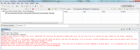
the motor stops and CCS5 gives an error.

Does this error related to GPIO current drive strength?

I configured the GPIO  not to be open drain. (GPIOODR = 0)

Also I didn't touch GPIODR2R, GPIODR4R, GPIODR8R, and GPIOSLR.

I'm using CCS5.1, TMS320-XDS100-V3

  • Hello Min-Ku,

    Is the motor deriving it's power from the board? If yes, then it could be possible that it is causing a shutdown of the LDO on board..

    Regards

    Amit

  • Hello Amit. Unfortunately, I use the power from the board.

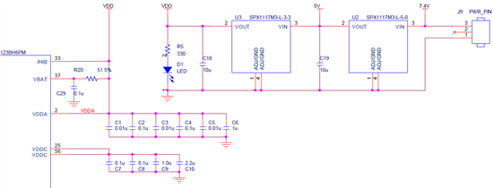
    I use a LiPo 7.4 battery. It goes through 2 regulators.(5V and VDD = 3.3V)

    You're talking about the On-chip Low Drop-Out Regulator right?

    Then what setting should be done to LDO registers?

    Always appreciate your help!

  • Hello Min-Ku

    What is the mAh rating for the battery? Can it supply sufficient current to the motor, the %v devices and the 3.3V devices?

    Can you replace it with a Power Supply and then see if the issue reproduces?

    Also the TM4C has a BOR bit, can you check that if BOR is set as Reset Source then does the RESC register in System Control show BOR as the cause of the reset? or is POR.

    Can you also connect a scope,probe to 3.3V line so that it can be checked if the voltage drops or not?

    Regards

    Amit

  • Hi Min-Ku,

    i did this to find out the reset-reason:

    #include "driverlib/sysctl.h"
    
    uint32_t resc = SysCtlResetCauseGet();
    UARTprintf("##RESET-INFO:"  \
    		"\tSYSCTL_CAUSE_HSRVREQ  %d\n" \
    		"\tSYSCTL_CAUSE_HIB      %d\n" \
    		"\tSYSCTL_CAUSE_LDO      %d\n" \
    		"\tSYSCTL_CAUSE_WDOG1    %d\n" \
    		"\tSYSCTL_CAUSE_SW       %d\n" \
    		"\tSYSCTL_CAUSE_WDOG0    %d\n" \
    		"\tSYSCTL_CAUSE_WDOG     %d\n" \
    		"\tSYSCTL_CAUSE_BOR      %d\n" \
    		"\tSYSCTL_CAUSE_POR      %d\n" \
    		"\tSYSCTL_CAUSE_EXT      %d\n",
    		(resc & SYSCTL_CAUSE_HSRVREQ) ? 1 : 0,
    		(resc & SYSCTL_CAUSE_HIB) ? 1 : 0,
    		(resc & SYSCTL_CAUSE_LDO) ? 1 : 0,
    		(resc & SYSCTL_CAUSE_WDOG1) ? 1 : 0,
    		(resc & SYSCTL_CAUSE_SW) ? 1 : 0,
    		(resc & SYSCTL_CAUSE_WDOG0) ? 1 : 0,
    		(resc & SYSCTL_CAUSE_WDOG) ? 1 : 0,
    		(resc & SYSCTL_CAUSE_BOR) ? 1 : 0,
    		(resc & SYSCTL_CAUSE_POR) ? 1 : 0,
    		(resc & SYSCTL_CAUSE_EXT) ? 1 : 0
    );

    The SYSCTL_CAUSE_LDO flag seems to have been taken out in the 2.1 release of TivaWare.

    Cheers

    Janos

  • Thanks Janos!!! (This is the battery I use.)

    I used the digital multimeter to see whether the 3.3V lines.

    The multimeter showed that there was no voltage drops. Neither at the VDDC pins.

    I have an additional question. How can I take out the SYSCTL_CAUSE_LDO flag?

    What function(functions from TIVAWARE) is used? Or what register should be written?

  • Hello Min-Ku,

    A multimeter will not show instantaneous voltage drops. Once the CCS debugger hangs, and you try to connect to the device, can you check the SYSCTL.RESC register and Fault Register (0xE000ED28 and 0xE000ED38)

    Also the PWM module has a fault pin. Is it connected to something or is it configured and left floating. Maybe that may also help

    Regards

    Amit

  • Hello Amit, it took a while to understand the problem.

    As you adviced, there was a serious problem going to the Vdd pins.

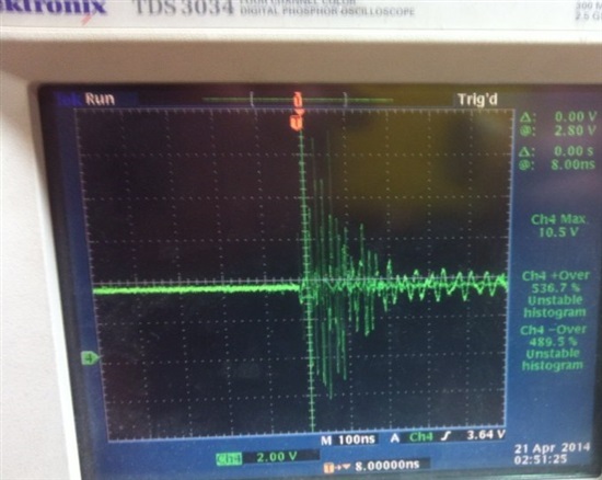
    The 3.3V was steady, but when I connected the DC Motor, the Vdd pin gone crazy.

    Also, the motor driver gets hot. It becomes toasted.

    Suddenly, the maximun voltage was 10.5V and the positive overshoot was 536.7%.

    While I was checking, the MCU is not working properly. Now the PB6 pin is giving 5Vs....

    So I couldn't check the SYSCTL.RESC register and Fault Register.

    Plus, I'm using PF2 for SSI communication and GPIO PD6, PD2 is floating. I didn't check the M0FAULT0 yet.

    Before connecting the DC motor, I gave PWM pulse at PB6 and GND-ed PB7. However the picture above is the pulse when I connect the motor. I don't understand why the GND pin gets weird voltages. It goes up almost 1.52V.

    Also the PB6 pulse wasn't like that. It showed clear rectangular shape pulse with 7.4V amplitude. However it goes weird too after connecting the DC motor.

    Do I have to connect Ferrite bead or 0 Ohm resistor to kill the noise?

    Or use other ICs like LM2734Y(1A Load Step-Down DC-DC Regulator)?

    (I searched the Arduino Due's schematic and it had LM2734Y. Changing the connection to the Arduino Due however worked. The motor driver ran normally.)

    Or there might be another problem?

    This file is my schematic.

    2318.Schematic.pdf

    Always thank you, Amit and also thank you too Janos.

    Regards, Min-Ku

  • Hello Min-Ku

    Having a ferrite bead would help suppress high frequency noise. Also how well are the two boards GND-ed. The GND bounce seen is due to charging of the GND plane which would cause all signals to be shifted.

    Also how is the supply to the motor coming? I would be looking at the schematic though but changes on the Arduino may be helpful to incorporate on your existing board.

    Regards

    Amit

  • Hello Amit.

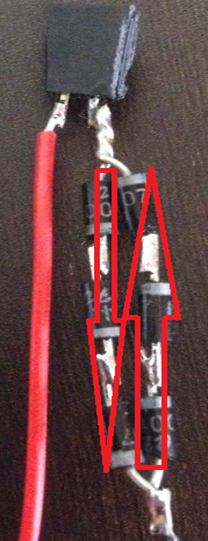
    I've added rectifier diodes to the motor driver's output pin. I used 6 of them.

    Making a parallel circuit with 3 series of diodes, the ground level had less noise.

    Before connecting the diodes, the ground level was slopping madly. However, it seems that I had used too many

    volts. Usually the LiPo battery was 7.4V, but I overcharged it to 8.4V.

    So I dropped the voltages with the diodes.

    It seems the motor and the MCU are stable when supplying about 7.4V.

    Although the motor driver and the diodes gets hot up to 40℃, the MCU worked fine.

    My silly knowledge brought chaos to all....T^T. Sorry about that.

    Anyways thank you so much to you guys!

    Regards, Min-Ku

  • Hello Min-Ku

    Commendable on finding the root cause and fixing it. I think you should mark a "Verified" for yourself :-)

    As for the temp of the package it will work all the way to max limit so 40C is not to worry.

    Regards

    Amit

  • Min-Ku Yeo said:
    This file is my schematic.

     Hi Min, I got an eye to your schematic, no capacitor are connected to motor driver, nor inductor filter is in place. On LM117 regulators some ceramic capacitor are needed in parallel to 10uF ones, a bigger 100-1000uF is necessary near the motor too and proper ground path must isolate noise from motor to enter microcontroller so power to micro must came out from big capacitor and never share the plane of CPU. Again motor driver ground need to be very short to capacitor. Power from battery and to cpu must leave capacitor node from opposite direction too. A cut in large plane also help separate from noise.

     Diode between driver and motor just reduce efficiency but not noise.

     Pin Sa, Sb on your schematic where connected to ground, a better idea is to insert a small Ohm resistor to measure current and to evaluate torque of motor too. An IC like INA195 198 can help interface directly to micro AD.

  • Hi Roberto, May I ask some questions?

    At the schematic, an 0.1uF cap was omitted (sorry for that).

    1. The 10uF cap at the regulators were specified at the datasheet.

    Is it okay to add bigger caps near?

    2. Can I ask the reason why a bigger cap is needed? (datasheet of regulator : 7230.SPX1117M3-L-3-3, -L-5-0(Regulator).pdf)

    For example, i have a 220uF electrolytic cap and suppose I add it parallel to 10uF cap.

    Since it's parallel, the actual capacitance is 230uF.

    As far as I know, cap decoupling is needed to stablize DC voltage

    and filter AC components due to capacitive reactance (1/2 pi f C).

    Then increasing the capacitance will decrease the cut-off frequency?

    3. As you mentioned 'placing a cap near the motor', what pins should be connected with the cap?

    4. I can't understand isolate noise from the motor to enter microcontroller and sharing the plane of CPU.

    I'm sorry but can you explain it again? T.T

    5. I'm trying to use the INA195 you suggested, but I don't know how to apply this and what this is for.

    What is the role of this IC?

    Thanks for your tip.

    Regards, Min-Ku