This thread has been locked.

If you have a related question, please click the "Ask a related question" button in the top right corner. The newly created question will be automatically linked to this question.

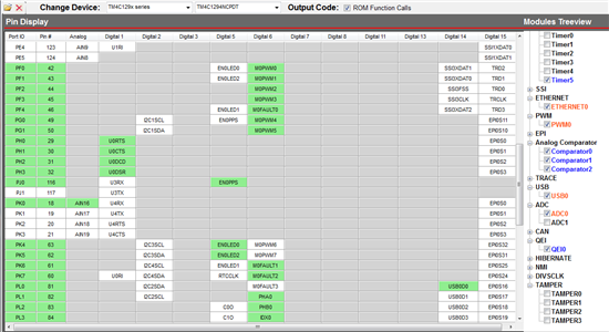
Tiva C PinMux Utility 1.0.4 TM4C1294NCPDT Eth0 LED's fall prey to PWM6-7

Guru 54077 points
Other Parts Discussed in Thread: EK-TM4C1294XL, TM4C129XNCZAD, DRV8301

Merely flagging this issue for revision 3 silicon modifications of TM4C129NCPDT revision 1 silicon.

When PWM0 - M0PWM0,1 & M0PWM6,7 pins are enabled & ETH0 is also enabled EN0LED 0-2 become orphaned GPIO pins, seemingly non routable to any other free GPIO pins.

Regarding the EK-TM4C1294XL circuit board when PWM0-M0PWM0,1 & Fault inputs M0Fault1 is made enabled;

When PWM0 - M0PWM6 or M0PWM7 are disabled M0PWM0,1 enabled and M0Fault0 & 1 are enabled. Then EN0LED1 PF4 pin 46 & EN0LED0 PF0 pin 42, circuit trace must be cut and rerouted to PK5 pin 62, PK4 pin 63 respectively.  EN0LED1 blink re-program as EN0LED2 blink thereby freeing up PK6 pin 61 GPIO input for M0Fault1, PF0-pin42 for M0PWM0 and PF4-pin46 for M0PWM3.

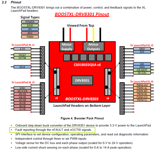
Appears the DRV801 BP does not conform to the EK-TMC129xl PWM pin assignments as anyone might expect they should. Merely judging the PCB visual layout as being compatible could end up porting mostly billowing smoke.


  • Hello Brett,

    Ethernet LED Pins have a dedicated pin map to PF0, PF1 and PF4 on the TM4C129 device. There is no change expected on this.

    Regards

    Amit

  • ETH0 peripheral LED assignments appear to have mappings PF0,1,4 & PK4,5,6. Seemingly the GPIO pin MUX should be able to reassign PF~ or PK~ to any available GPIO port. 

    GPIO pin MUX orphaning any pins in my opinion violates the very purpose allowing EASY reroute peripheral pins to a physical external port on the GPIO module either by HWD AFSEL or by digital at the ETH0 peripheral register level.


  • Hello Brett,

    I agree, that the Pin Mux utility should be able to map Ethernet LED pins to either PFx or PKy ports. If prohibits the assignment then it is an issue with the PinMux utility (thanks to bring it to our notice) and I will check that. Did you check the TM4C129XNCZAD part as it allows for more PinMux Options and if you plan to do the application which requires more flexibility, I will suggest this part.

    However if the concern is w,r,t this not being available on EK-TM4C129 then, there are limitations when trying to do Eval Board as all options may not be routed.

    Regards

    Amit

  • The real issue is that all ETH0 LED's become orphaned when PWM0-7 outputs are needed. Thankfully can use Timer 5 in PWM down count for a fan speed control or at least that's the game plan.  I was able to cut the PCB trace right at the anode of D2 & D3 wired to X7-3-PK4 & X7-5-PK5 freeing up ETH0 LEDS PF0 & PF4 for M0PWM0 & M0FAULT0.

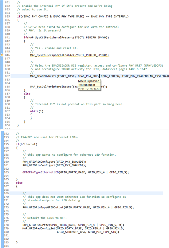
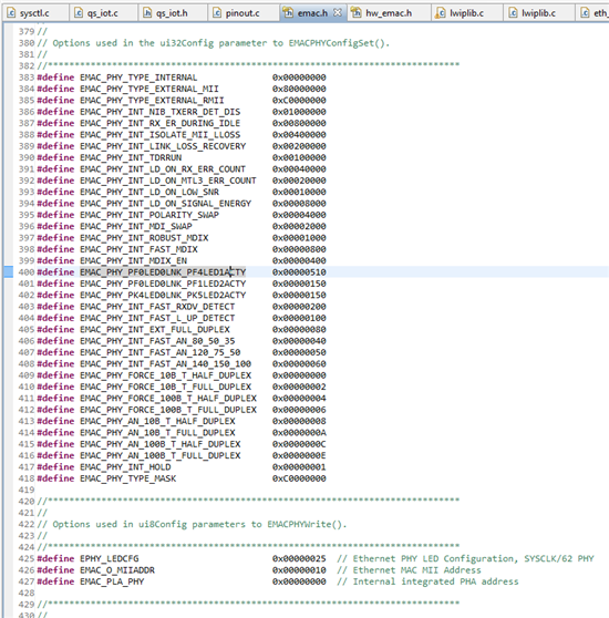
    ETH0 PHY was using reset default register values in (Lwip.c) for LED control and no defines were added in (emac.h) allowing LED re-assignments. Accessing M37 via MIEMACADDR management interface in order to change EPHYLEDCFG is no easy task even after adding a few defines switch LED1 started flashing then just stopped.

  • Hello Brett

    That is why I am suggesting if a custom board needs to be done and having these functions existing together like PWM0-7 and Ethernet Internal PHY with LED, then a TM4C129XNCZAD device should be selected

    But if the question is to the LaunchPad then I believe what you have done does make a lot sense

    Regards

    Amit

  • Yes the launch pad is the target being used with Exocite IoT, adding a PWM bridge driver on the X11 interface. Noticed the DRV8301 PWM Booster Pack will not work with the EK-TM4C1294XL, PWM0-5 are not able to relocate to the static PWM pins on the DRV8301 BP. Will consider the 129XNCZAD but not having much luck soldering any LQFP chips on PCB as replacements without getting future random cold solder joints.  

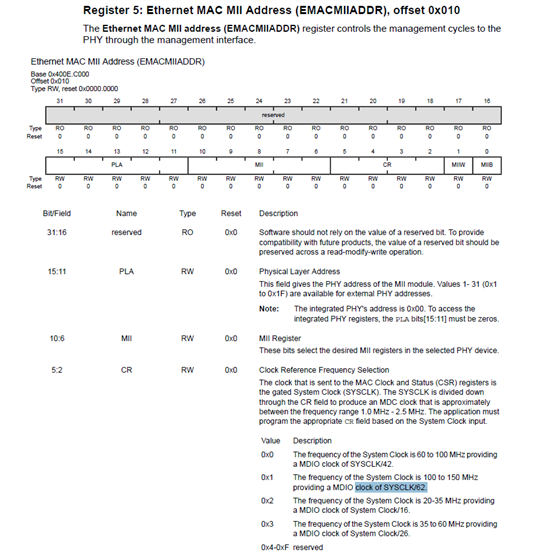
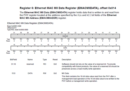
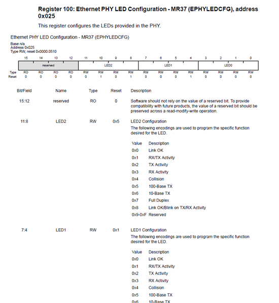
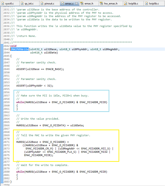
    Found the EMAC SYSCLK clock divider buried in the EMACADDRII 0x400E.C000:0x10 register also used to set the address into the PHY device M37 address in management interface used to configure ETH0 LEDS as (ui16data). That (emac.c) function (below) is not working to set the EN0LED2 binary register from the default setting LINK desired to be  TXRX activity. The ETH0 LED configuration defines can be found in (hw_emac.h) or copy into (emac.h) needed ones such as (EMAC_MIIADDR_CR_100_150 SYSCLK) divider when addressing the EMACADDRII register used to access M37 and set the ETH0 LEDS. Both the M37 address with a divider and without behave the same.

    Mistakenly setting the PLA address other then 0x00 for 0x010 and GPIO PN1- LED1 would blink activity. Believe blink for UART0 transmit activity and then LED1 just turns off. Both PK4-ETH0LED3 ,PK5-ETHLED4 are detecting ETH0 Link and turn off when the Ethernet cable is unplugged. 

    Does it appear I'm setting the EH0LED2 correctly?

  • BTW: Data sheet 20.5.2.4 states the default for ETH0LED2 is TX/RX activity and as shown above the PHY MR37 LED2  show reset value as 0x5.


    Can't find any code that writes to M37 setting ETH0LED,0-2 and therefore must be using M37 LED reset values.

  • Hello Bret,

    The configuration for EMACPhyWrite is correct and thanks for pointing the data sheet error. Will get that fixed as well.

    Regards

    Amit

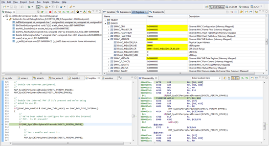
  • Thanks Amit, Looking now 6 hours into an dysfunctional LED, don't take kindly to an LED kicking my butt however this is no ordinary LED so must cut it some slack. Wonder why ETH0LED2 can not be set blinking? Even have try out other ETH0LED2/1 combined values such as 0x00000880 and you see the PHY is being reset right after the MAC updates in the management interface.

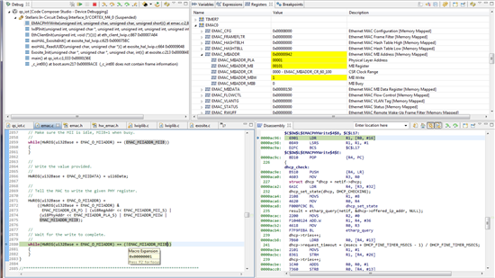
    If not errata suspect possibly the busy test of PHY (blue box) or variable in the (yellow box) is not performing as expected. The yellow box has me scratching head what register is being accessed etc..


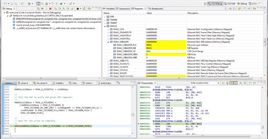
  • According to ICDI debug output the yellow box is not concatenating correct PHY data in order to set ETH0LEDS accordingly. Seemingly the CSA register is also not keeping the correct MDC clock frequency during the write. After the write of PHY the CSA returns to an MDIO clock derived SYSCLK/62 as EMAC_MIIADDR_CR of 0001. I modify both zero flag while loops and verified that part appears very functional. The heavy part  getting lost in is the concatenation values are way off because the PHY M37 address equals 943 decimal or 0x000003AE.

    Can you guys look at this Tiva function and see what's up?

  • Hi Amit,

    This function sequence appears to have been written to handle external PHY writes (above address 0x0:0h) very effectively while in all practicality it should be available for internal MAC writes of the internal PHY Ethernet peripheral.  

    It appears left shifting via (EMAC_MIIADDR_PLA_S) the internal PHY physical address given as (ui8Phyaddr, 0x00000000) does not shift the entire EMACMIIADDR register 12 bit positions to the left as the code is written to do.

    Good lesson proving one can not left shift or right shift zero any bit positions though suspect this was not the intention of the original code piece.

  • Hello Brett

    The function works well for both external and internal PHY and with PHY Address of 0x0. Why would a left shift of 0 cause any problem. Can you elaborate?

    Regards

    Amit

  • Was confused seeing 942 in the EMAC_MIIADDR register, M37 0x25 as 100101 shown without register bit positions.

    Shouldn't that be 0x25 = 100101 and PLA was showing as 001 should be 0000?

    However just my opinion masking (ui8PhyAddr & EMAC_MIIADDR_PLA_MASK) as 0x00007800 seems more appropriate than left shifting zero.

    Looks as if the CSR clock range divisor switching to ~60_100 (SYSCLK/42) during the MAC --> PHY write cycle is the real issue when MDIO clock should be (SYSCLK/62) when the SYSCLK = 100-150 MHZ.

    Of course believe that the case if the PHY M37 address 0x25 hardware is not without problems.

  • Hello Brett

    Using the ui8PhyAddr in this notification would mean that the user has to shift the bits before masking it. This is more prone to errors than it would be for the user to give the ui8PhyAddr and let the API move it into correct position. Secondly, the PLA Mask would be 0x0000F800 (Bits 15-11)

    As fr the PLA for M37 it should be 0x25 (100101). However this address resides in the extended address region and the data sheet section "Extended Address Space Access".

    Regards

    Amit

  • See your point on the shift versus mask for other situations and made that correction earlier 0x25 (10010) had you gone to the forum page that would be apparent along with Debug output showing the M37 register is being shifted into the PHY bit field by one bit position as shown below.  Noticed that 0x00007800 also made that same mistake in the opposite direction though it had no effect of the shifted M37 outcome. Forced the DIO clock /64 so it doesn't change during the PHY write later discovered clock divisor was being set during EMACInit() below where I was trying to program the M37 register, might explain the clock rate changing during PHY write but not the MII register shifting into the PLA.

    Believe your inferring the (Mxx) registers are MII Management (Accessed through the EMACMIIADDR Register) page 1471. That is the method being used here to set ETH0LED2 Tx/Rx activity proof of the debug output screen shown below and above the function is not working correctly. The extend registers differ from the Mxx registers from what was read of them did not see any reason to go there.


  • Hello Brett,

    The EMACPhyRead/Write is meant for registers from 0x00 to 0x1F. For extended register access the API is EMACPhyExtendedRead/Write

    Agreed that there is no check on the MII Address going into PLA for the EMACPhyRead/Write. This needs to be corrected in some way.

    Regards

    Amit

  • The EMACPhyRead/Write is meant for registers from 0x00 to 0x1F. For extended register access the API is EMACPhyExtendedRead/Write:

    Amit, with due respect disagree with that statement as the text page 1462 states :

    The PHY SMI function supports read/write accesses to the extended register set using Ethernet PHY Register Control - MR13 (EPHYREGCTL) register and the Ethernet PHY Address or Data - MR14 (EPHYADDAR) registers. Accessing the standard register set, MDIO registers 0 to 31. <Might that 31 be a typo. Decimal MR37 = 0x25 not 1F and actually read as extended?

    There are 65 EMAC +3 EPHY registers and 32 EPHY registers if you count them in the register map as I did.

    The register map 20.6 in bold print page 1471 has written above the 29 MXX registers:

    MII Management (Accessed through the EMACMIIADDR Register) page 1486.

    There is only one EMACMIIADDR register.

    Belive the Debug window is showing the read back of data previously written into the MII and PLA register shifted one bit position from MII into the PLA. Either SW is shifting the bits incorrctly  prior to write or this register has issues in the silicon. Of coures that is my take on what is happening after reading the text and viewing the diagrams of the register map.

  • Amit,

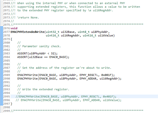
    Success with a twist of lime (or) green flashing ETH0_LED2. That text (or Data-MR14) uses the word OR meaning to me either this way or that way but not both at the same time. Would never have figured the MRxx registers are the extend access being referenced in that paragraph and still don't fully understand what its talking about.

    Resetting the PHY after the extended write was dropping the MR37 LED register change. Guessing the reason of 0x401F and need to do a double extended write is unknown, though it seemingly would undo what was done. Possibly the 4:0 in the register MR13 was mistaken to imply a DEVAD 0x401F?

    Possibly this area of the text could be better elaborated if the PHY diagram had a line drawn from the (LED Drivers) box to the extended box page 1460 and add some more info about who DEVAD is.


  • Even more interesting is CCS compiler 5.4.1 is handing off the PHY write value into EMAC MR14 to a variable in the same position with a different name. The "this or that one" text part appears also proven true. For some reason EMAC MR14 write to PHY in extended write was not liking EMACPHYwrite() of the same LED data.

    Example:

    uint16_tui16Value of EMACPHYExtendedWrite() is pasted into EMACPHYwrite()  as (uint16_tui16Data) during the write as

    HWREG(ui32Base + EMAC_O_MIIDATA) = ui16Data; // EMAC PHY write MR14

    Amit thanks again for the added insight!

  • Several here wonder now if esteemed oil firm will change their corp name to Brett Price - as you've assumed their earlier BP moniker...