This thread has been locked.

If you have a related question, please click the "Ask a related question" button in the top right corner. The newly created question will be automatically linked to this question.

Problem with the raster_example

Hello, my case is as follows:

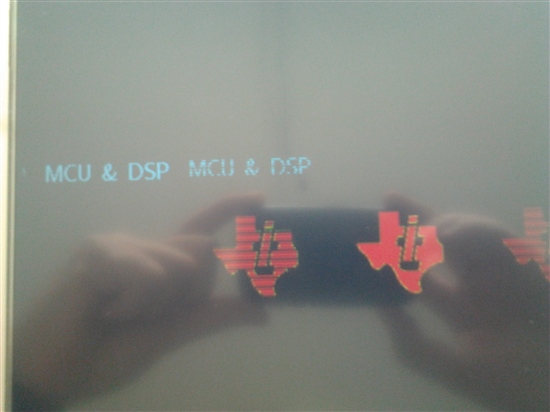
I'm using the tool DK-TM4C129 with a TFT LCD 10 " screen 640x480, the what can only operate in raster mode via the LCD driver MCU. I used the sample code "raster_example" which comes in the "TivaWare_C_Series-2.1.0 package. I've made ​​some changes to the code to display correct information. The problem I have is that the objects sent me the screen always repeated in another position on the screen but distorted. Add source code.

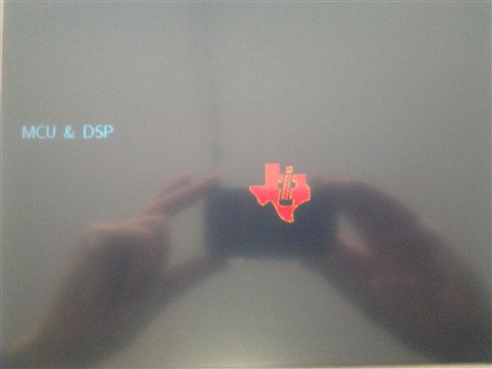
I have been making changes in synchrony times to see if the problem is here but does not correct the problem. I hope you can help me see what is happening. Also I have a photo of the image you see where the error is better appreciated.

6278.main.c
//*****************************************************************************
//
// raster_example.c - An example showing the use of the TM4C129x LCD
//                    controller in raster mode.
//
// Copyright (c) 2012-2014 Texas Instruments Incorporated.  All rights reserved.
// Software License Agreement
//
//   Redistribution and use in source and binary forms, with or without
//   modification, are permitted provided that the following conditions
//   are met:
//
//   Redistributions of source code must retain the above copyright
//   notice, this list of conditions and the following disclaimer.
//
//   Redistributions in binary form must reproduce the above copyright
//   notice, this list of conditions and the following disclaimer in the
//   documentation and/or other materials provided with the
//   distribution.
//
//   Neither the name of Texas Instruments Incorporated nor the names of
//   its contributors may be used to endorse or promote products derived
//   from this software without specific prior written permission.
//
// THIS SOFTWARE IS PROVIDED BY THE COPYRIGHT HOLDERS AND CONTRIBUTORS
// "AS IS" AND ANY EXPRESS OR IMPLIED WARRANTIES, INCLUDING, BUT NOT
// LIMITED TO, THE IMPLIED WARRANTIES OF MERCHANTABILITY AND FITNESS FOR
// A PARTICULAR PURPOSE ARE DISCLAIMED. IN NO EVENT SHALL THE COPYRIGHT
// OWNER OR CONTRIBUTORS BE LIABLE FOR ANY DIRECT, INDIRECT, INCIDENTAL,
// SPECIAL, EXEMPLARY, OR CONSEQUENTIAL DAMAGES (INCLUDING, BUT NOT
// LIMITED TO, PROCUREMENT OF SUBSTITUTE GOODS OR SERVICES; LOSS OF USE,
// DATA, OR PROFITS; OR BUSINESS INTERRUPTION) HOWEVER CAUSED AND ON ANY
// THEORY OF LIABILITY, WHETHER IN CONTRACT, STRICT LIABILITY, OR TORT
// (INCLUDING NEGLIGENCE OR OTHERWISE) ARISING IN ANY WAY OUT OF THE USE
// OF THIS SOFTWARE, EVEN IF ADVISED OF THE POSSIBILITY OF SUCH DAMAGE.
//
// This is part of revision 2.1.0.12573 of the Tiva Firmware Development Package.
//
//*****************************************************************************

#include <stdint.h>
#include <stdbool.h>
#include "inc/hw_sysctl.h"
#include "inc/hw_types.h"
#include "inc/hw_memmap.h"
#include "inc/hw_gpio.h"
#include "inc/hw_ints.h"
#include "inc/hw_lcd.h"
#include "driverlib/sysctl.h"
#include "driverlib/gpio.h"
#include "driverlib/lcd.h"
#include "driverlib/interrupt.h"
#include "driverlib/rom.h"
#include "driverlib/rom_map.h"
#include "grlib/grlib.h"
#include "utils/uartstdio.h"
#include "utils/ustdlib.h"
#include "drivers/grlib_raster_driver_1bpp.h"
#include "drivers/grlib_raster_driver_4bpp.h"
#include "drivers/grlib_raster_driver_8bpp.h"
#include "drivers/grlib_raster_driver_16bpp.h"
#include "drivers/raster_displays.h"
#include "drivers/sdram.h"

#define LXD_DISPLAY

#define RASTER_WIDTH  640
#define RASTER_HEIGHT 480


//*****************************************************************************
//
//! \addtogroup lcd_examples_list
//! <h1>LCD Controller Raster Mode Example (raster_example)</h1>
//!
//! This application illustrates the use of the Tivaware Graphics Library
//! and Tiva TM4C129x LCD controller driving an 800x480 display using raster
//! (HSYNC/VSYNC/ACTIVE/DATA) mode.  The display is initialized and enabled
//! then a simple pattern including lines, a small image, some text and a
//! circle is displayed.
//!
//! By default, the application is set up to support an Innolux EJ090NA-03A
//! display with 800x480 resolution, refreshed at 60Hz from a 16bpp frame
//! buffer stored in SDRAM.  The SDRAM is attached to the MCU via the External
//! Peripheral Interface (EPI) module.  The file drivers/raster_displays.c
//! contains timings and initialization functions for several other displays
//! and the application can be easily rebuilt to support any of these by
//! replacing the preprocessor define ``\b INNOLUX_DISPLAY'' with one of the
//! other display labels:
//!
//! - \b OPTREX_DISPLAY supports an Optrex T-55226D043J-LW-A-AAN in 800x480
//! with 75Hz refresh rate.
//! - \b LXD_DISPLAY supports an LXD M7170A in 640x480 with 60Hz refresh rate.
//! - \b FORMIKE_DISPLAY supports at Formike KWH070KQ13 in 800x480 with 60Hz
//! refresh rate.
//!
//! Display interface timing information and any required initialization code
//! is included in the file lcd/drivers/raster_displays.c.  New raster-mode
//! displays can be added to this file and raster_displays.h very easily and
//! used by the application merely by adding another display label and
//! appropriate code to set the tRasterDisplayInfo timing structure for that
//! display at the top of raster_example.c.
//!
//! Once appropriate display timings have been determined, the display can be
//! used by the TivaWare Graphics Library via one of the supplied raster mode
//! display drivers.  Four distinct drivers are supplied in the lcd/drivers
//! directory, each supporting a different color depth for the frame buffer:
//!
//! - \b grlib_raster_driver_1bpp.c supports a monochrome (2 color) display
//! buffer.
//! - \b grlib_raster_driver_4bpp.c supports a 4 bit per pixel (16 color) frame
//! buffer.
//! - \b grlib_raster_driver_8bpp supports an 8 bit per pixel (256 color) frame
//! buffer.
//! - \b grlib_raster_driver_16bpp supports a 16 bit per pixel (65536 color)
//! frame buffer.
//!
//! The size of frame buffer required varies with the resolution of the LCD
//! display in use and the desired frame buffer color depth.  Note that the
//! frame buffer color depth may be lower than the native color resolution of
//! the LCD panel - the LCD controller makes use of a color lookup table or
//! palette to convert the pixels in the frame buffer to the correct color
//! format for the LCD's hardware interface.
//!
//! The size of frame buffer, in bytes, can be determined using the following
//! formula:
//!
//! Buffer Size = X * Y * (BPP / 8) + (Header Size)
//!
//! where:
//!
//! - X is the horizontal pixel resolution of the LCD panel
//! - Y is the vertical pixel resolution of the LCD panel
//! - BPP is the desired number of bits per pixel for the frame buffer
//! - Header Size is 512 for 8bpp frame buffers or 32 for all other color
//! resolutions.
//!
//! The frame buffer header contains information informing the LCD controller
//! of the pixel format in the frame buffer and also the color lookup table
//! used for 1, 4 and 8bpp cases.  Note that a 32 byte header is still required
//! even when using 16bpp frame buffers which do not require a color lookup
//! table.
//!
//! For large panels such as those described in raster_displays.h, a frame
//! buffer supporting more than two colors is likely to be too large to fit
//! in the internal memory of a TM4C129x device and would, therefore, require
//! the use of external, EPI-connected SDRAM.  The 16bpp 800x480 frame buffer
//! used in this application requires almost 940KB of RAM for example. For lower
//! resolution displays or lower color depths, internal SRAM may be suitable
//! for use as the frame buffer.  For example, a 16bpp QVGA (320x240) frame
//! buffer occupies about 150KB of storage and a monochrome (1bpp) 800x480
//! frame buffer needs only 48KB.
//
//*****************************************************************************

//*****************************************************************************
//
// Pointer to EPI SDRAM if available.
//
//*****************************************************************************
uint16_t *g_pui16SDRAM;

//*****************************************************************************
//
// Frame buffer and palette size.
//
//*****************************************************************************
#ifdef OPTREX_DISPLAY
const tRasterDisplayInfo *g_psDisplayMode = &g_sOptrex800x480x75Hz;
#define SCREEN_BPP    16
#else
#ifdef LXD_DISPLAY
const tRasterDisplayInfo *g_psDisplayMode = &g_sLXD640x480x60Hz;
#define SCREEN_BPP    16
#else
#ifdef FORMIKE_DISPLAY
const tRasterDisplayInfo *g_psDisplayMode = &g_sFormike800x480x60Hz;
#define SCREEN_BPP    16
#else
#ifdef INNOLUX_DISPLAY
const tRasterDisplayInfo *g_psDisplayMode = &g_sInnoLux800x480x60Hz;
#define SCREEN_BPP    16
#else
#error Target display type is not defined!
#endif
#endif
#endif
#endif

#define SIZE_BUFFER ((RASTER_WIDTH * RASTER_HEIGHT * SCREEN_BPP) / 8)
#define SIZE_PALETTE ((SCREEN_BPP == 8) ? (256 * 2) : (16 * 2))

//*****************************************************************************
//
// Pointers to the frame buffer into SDRAM.
//
//*****************************************************************************
uint32_t *g_pui32DisplayBuffer;
uint16_t *g_pui16Palette;

#if SCREEN_BPP == 8
#define NUM_PAL_ENTRIES 256
#else
#define NUM_PAL_ENTRIES 16
#endif

const uint32_t g_pulSrcPalette[NUM_PAL_ENTRIES] =
{
    ClrBlack,
    ClrWhite,
    ClrRed,
    0x00FF00,
    ClrBlue,
    ClrYellow,
    ClrMagenta,
    ClrCyan,
    ClrOrange,
    ClrDarkBlue,
    ClrGold,
    ClrOrange,
    ClrCrimson,
    ClrDarkTurquoise,
    ClrDarkGray,
    ClrSilver,
};

//*****************************************************************************
//
// A couple of macros used to extract the dimensions from an image.
//
//*****************************************************************************
#define IMAGE_WIDTH(ptr) ((*(uint16_t *)((uint8_t *)(ptr) + 1)))
#define IMAGE_HEIGHT(ptr) ((*(uint16_t *)((uint8_t *)(ptr) + 3)))

//*****************************************************************************
//
// Graphics context used to show text on the QVGA display.
//
//*****************************************************************************
tContext g_sContext;

//*****************************************************************************
//
// Global interrupt status flags.
//
//*****************************************************************************
static volatile uint32_t g_ui32Flags;
static volatile uint32_t g_ui32FrameCounter;
static volatile uint32_t g_ui32UnderflowCount;

//*****************************************************************************
//
// The image of the TI logo.
//
//*****************************************************************************
const unsigned char g_pucLogo[] =
{
    IMAGE_FMT_4BPP_COMP,
    80, 0,
    75, 0,

    15,
    0x00, 0x00, 0x00,
    0x02, 0x02, 0x0f,
    0x06, 0x05, 0x27,
    0x09, 0x07, 0x3b,
    0x0c, 0x09, 0x4c,
    0x0d, 0x0a, 0x56,
    0x10, 0x0c, 0x68,
    0x13, 0x0f, 0x7a,
    0x15, 0x10, 0x89,
    0x17, 0x11, 0x95,
    0x19, 0x14, 0xa5,
    0x1c, 0x16, 0xb6,
    0x1e, 0x18, 0xc7,
    0x22, 0x1a, 0xdc,
    0x22, 0x1b, 0xe3,
    0x24, 0x1c, 0xed,

    0xfc, 0x07, 0x07, 0x07, 0x07, 0x07, 0x03, 0x04, 0xfe, 0x13, 0xee, 0xee,
    0xee, 0xe9, 0xef, 0xd1, 0x07, 0x07, 0xc2, 0x77, 0x29, 0x04, 0xff, 0xff,
    0xff, 0xe9, 0xff, 0x3c, 0xff, 0xd1, 0x07, 0x07, 0x77, 0x29, 0x04, 0xff,
    0x23, 0xff, 0xff, 0xe9, 0xff, 0xff, 0xd1, 0x07, 0x07, 0xc2, 0x77, 0x29,
    0x04, 0xff, 0xff, 0xff, 0xe9, 0xff, 0x2e, 0xff, 0xd1, 0x05, 0x01, 0x07,
    0xbf, 0x32, 0x04, 0x11, 0xff, 0xff, 0xff, 0xe9, 0xff, 0xff, 0xd1, 0x02,
    0x0e, 0x6f, 0xdc, 0xdc, 0xf7, 0x07, 0xbf, 0x32, 0x04, 0x11, 0xff, 0xff,
    0xff, 0xe9, 0xff, 0xff, 0xd1, 0x02, 0x0e, 0xaf, 0xff, 0xff, 0xf5, 0x07,
    0xbf, 0x32, 0x04, 0x11, 0xff, 0xff, 0xff, 0xe9, 0xff, 0xff, 0xd1, 0x02,
    0x0e, 0xdf, 0xff, 0xff, 0xf2, 0x07, 0xbf, 0x32, 0x04, 0x11, 0xff, 0xff,
    0xff, 0xe9, 0xff, 0xff, 0xd1, 0x01, 0x73, 0x01, 0xc5, 0x07, 0xa7, 0x00,
    0x04, 0x29, 0x11, 0xae, 0x04, 0x03, 0x99, 0xa0, 0x07, 0xbf, 0x72, 0x04,
    0xc5, 0x29, 0x11, 0xff, 0xff, 0xd1, 0x01, 0x08, 0x99, 0x76, 0x70, 0x07,
    0xbf, 0x72, 0x04, 0x29, 0x11, 0xff, 0x20, 0xff, 0xd1, 0x01, 0x07, 0xcb,
    0xbb, 0xbc, 0x40, 0xe1, 0x07, 0xbf, 0x72, 0x04, 0xff, 0xff, 0xff, 0xe9,
    0x1e, 0xff, 0xff, 0xd1, 0x07, 0x07, 0x77, 0x29, 0x04, 0x11, 0xff, 0xff,
    0xff, 0xe9, 0xff, 0xff, 0xd1, 0x07, 0xe1, 0x07, 0x77, 0x29, 0x04, 0xff,
    0xff, 0xff, 0xe9, 0x00, 0xff, 0xff, 0xe6, 0x45, 0x63, 0x00, 0x26, 0x55,
    0x2b, 0x55, 0x64, 0xda, 0x55, 0xe9, 0x51, 0x04, 0xd4, 0x03, 0x00, 0x00,
    0x04, 0xff, 0xff, 0xff, 0xe9, 0xd2, 0x03, 0xf7, 0x00, 0x6f, 0xff, 0xff,
    0xf9, 0xda, 0x62, 0x63, 0xf2, 0x04, 0xd4, 0x00, 0x00, 0x04, 0x54, 0x22,
    0x00, 0xf3, 0x00, 0x9f, 0xff, 0xff, 0xf6, 0x00, 0x8f, 0xb1, 0x74, 0xf2,
    0x04, 0xd4, 0x00, 0x00, 0x04, 0x54, 0x8e, 0x22, 0xd1, 0x00, 0xcf, 0x0a,
    0xd9, 0x62, 0xf2, 0xc6, 0x04, 0xd4, 0x00, 0x00, 0x04, 0x54, 0x22, 0xc0,
    0x45, 0x01, 0x01, 0xd1, 0x01, 0xef, 0x74, 0xf2, 0x04, 0x8c, 0xd4, 0x00,
    0x00, 0x04, 0x54, 0x22, 0x90, 0x03, 0xb6, 0x01, 0xb0, 0xda, 0x62, 0xf2,
    0x04, 0xd4, 0x00, 0x32, 0x00, 0x04, 0x4d, 0x11, 0x60, 0x06, 0x01, 0x90,
    0xd8, 0xda, 0x62, 0xf2, 0x04, 0xd4, 0x00, 0x00, 0x04, 0xcb, 0x4d, 0x11,
    0x30, 0x09, 0x01, 0x50, 0xda, 0x62, 0x62, 0xf2, 0x04, 0xd4, 0x00, 0x00,
    0x04, 0x4d, 0xff, 0x0b, 0xff, 0xfe, 0x10, 0x0c, 0x01, 0x30, 0xda, 0x62,
    0x62, 0xf2, 0x04, 0xd4, 0x00, 0x00, 0x04, 0x4d, 0xda, 0x00, 0xaa, 0xb9,
    0x00, 0x1e, 0xff, 0xff, 0xfe, 0x10, 0x0b, 0x1a, 0xba, 0xaa, 0xdf, 0x62,
    0xf2, 0x04, 0xd4, 0x1a, 0x00, 0x00, 0x04, 0x62, 0x41, 0x80, 0x49, 0x2f,
    0x12, 0xff, 0xff, 0xfb, 0x11, 0x01, 0xef, 0x62, 0xf3, 0xc6, 0x04, 0xd4,
    0x00, 0x00, 0x04, 0x62, 0x41, 0x60, 0x85, 0x49, 0x6f, 0xff, 0xff, 0xf8,
    0x6f, 0xf4, 0x04, 0xc4, 0xd4, 0x5e, 0xff, 0xff, 0x30, 0x49, 0x9f, 0xff,
    0x2b, 0xff, 0xf6, 0x11, 0x06, 0x6b, 0xf7, 0x04, 0xd4, 0x11, 0x00, 0x00,
    0x04, 0x5b, 0xff, 0xfe, 0x10, 0x49, 0x0a, 0xbf, 0xff, 0xff, 0xf3, 0x11,
    0x09, 0x6b, 0xfc, 0x86, 0x02, 0x05, 0x55, 0x55, 0x55, 0xe9, 0xd1, 0x38,
    0x90, 0x5b, 0xff, 0xfb, 0x01, 0x01, 0xef, 0xff, 0xff, 0x55, 0xd1, 0x11,
    0x0c, 0x6c, 0x40, 0x69, 0x0d, 0x14, 0xd5, 0x7c, 0x4a, 0xf9, 0x01, 0x03,
    0x01, 0xb0, 0x19, 0x56, 0x1f, 0x1c, 0xc0, 0x69, 0x09, 0x06, 0xc6, 0xf6,
    0xaa, 0x01, 0x06, 0x01, 0x80, 0x19, 0x3f, 0x1c, 0xfa, 0xb0, 0x69, 0x05,
    0x06, 0xc6, 0xf4, 0x02, 0x22, 0x00, 0x41, 0x08, 0x01, 0x50, 0x01, 0x22,
    0x20, 0x7f, 0x1d, 0x06, 0xb4, 0x00, 0x00, 0x00, 0xcf, 0x05, 0x6d, 0xff,
    0x04, 0xfe, 0xff, 0xfe, 0x10, 0x0b, 0x01, 0x20, 0x0c, 0x81, 0x3f, 0xff,
    0xf9, 0x00, 0x00, 0x00, 0x5f, 0x8f, 0x80, 0x46, 0xfc, 0x00, 0x1f, 0xff,
    0xff, 0xfe, 0x10, 0x40, 0x1e, 0x3f, 0xff, 0xf9, 0x00, 0x00, 0x00, 0x08,
    0xc0, 0x8f, 0x46, 0xfa, 0x00, 0x3f, 0xff, 0xff, 0xfb, 0xc0, 0xda, 0x2e,
    0xf9, 0x00, 0x00, 0x00, 0x00, 0x9f, 0xc0, 0x87, 0x3d, 0xf6, 0x00, 0x5f,
    0xff, 0xff, 0xf8, 0x20, 0x00, 0x6f, 0x47, 0xff, 0xf9, 0x00, 0x00, 0x00,
    0x30, 0x00, 0x08, 0x87, 0x3d, 0xf3, 0x00, 0x9f, 0xff, 0x30, 0xff, 0xf6,
    0xda, 0x36, 0xf9, 0x00, 0x00, 0x00, 0x18, 0x00, 0x00, 0x6f, 0x7f, 0x34,
    0xf1, 0x00, 0xcf, 0x18, 0xff, 0xff, 0xf3, 0xda, 0x3e, 0xf9, 0x00, 0x00,
    0x0c, 0x00, 0x00, 0x00, 0x05, 0x7f, 0x34, 0xc0, 0x01, 0x0c, 0xef, 0xff,
    0xff, 0xd0, 0xda, 0x3e, 0xf9, 0x00, 0x2c, 0x00, 0x00, 0xe9, 0x6f, 0x77,
    0x2b, 0x90, 0x02, 0x90, 0x01, 0xb0, 0x03, 0x5f, 0xff, 0xff, 0xf9, 0x00,
    0x2c, 0x00, 0x00, 0xe9, 0x09, 0x6f, 0x23, 0x60, 0x06, 0xb0, 0x01, 0x80,
    0xda, 0x46, 0xf9, 0x00, 0x00, 0x00, 0x99, 0xe9, 0x01, 0xdf, 0x67, 0x1a,
    0x30, 0x09, 0x01, 0x61, 0x50, 0xda, 0x4e, 0xf9, 0x00, 0x00, 0x00, 0xe9,
    0x31, 0x00, 0x7f, 0x67, 0x19, 0xfe, 0x10, 0x0b, 0x01, 0x61, 0x20, 0xda,
    0x4e, 0xf9, 0x00, 0x00, 0x00, 0xe9, 0x30, 0x00, 0x2f, 0x67, 0x19, 0xfc,
    0x00, 0x1e, 0xff, 0x08, 0xff, 0xfd, 0x10, 0x0c, 0x67, 0xff, 0xff, 0xf9,
    0x13, 0x00, 0x00, 0x00, 0xe9, 0x00, 0x0a, 0x67, 0x5b, 0x00, 0x3f, 0xee,
    0xee, 0xfb, 0x00, 0x05, 0xee, 0xed, 0x84, 0x6f, 0xf9, 0x00, 0x00, 0x00,
    0xe9, 0x00, 0x05, 0xc0, 0x77, 0x29, 0xf6, 0x00, 0x11, 0x11, 0x11, 0x11,
    0x08, 0x00, 0x00, 0x01, 0x04, 0x57, 0xf9, 0x00, 0x00, 0x44, 0x00, 0xe9,
    0x00, 0x00, 0xcf, 0x6f, 0xff, 0xff, 0x52, 0xf2, 0x5e, 0x06, 0x5e, 0xc8,
    0x42, 0x6e, 0x6f, 0x85, 0x6a, 0xfc, 0x42, 0x25, 0xdf, 0x29, 0xe1, 0x5e,
    0x42, 0x0a, 0x5a, 0xff, 0xff, 0xfd, 0x72, 0x7e, 0x00, 0x21, 0x00, 0x0c,
    0x6a, 0x90, 0x00, 0x00, 0x1c, 0x29, 0x63, 0xc0, 0x5f, 0x5a, 0xff, 0xfc,
    0x40, 0x86, 0x41, 0x50, 0x02, 0x01, 0xf8, 0x01, 0x01, 0xef, 0xff, 0xff,
    0x51, 0xc0, 0x46, 0x1e, 0x59, 0xff, 0xfb, 0x20, 0x8e, 0x84, 0x4b, 0x3f,
    0xff, 0xff, 0x90, 0x02, 0x5f, 0xff, 0x20, 0xff, 0xe1, 0x3e, 0x4f, 0xff,
    0xff, 0xff, 0xfd, 0x62, 0x30, 0x96, 0x54, 0x01, 0x6b, 0xb5, 0x0b, 0x0b,
    0x10, 0xff, 0xff, 0xf6, 0x36, 0x7f, 0xff, 0xff, 0xff, 0x74, 0x70, 0x9e,
    0x5e, 0x1d, 0x03, 0x27, 0x00, 0x00, 0x0e, 0x9f, 0xff, 0xff, 0xd2, 0x07,
    0xbf, 0x1d, 0xbf, 0x00, 0xff, 0xff, 0xfd, 0x96, 0x54, 0x33, 0x33, 0x33,
    0x03, 0x33, 0x32, 0xcf, 0xff, 0xfc, 0x10, 0x07, 0xbf, 0x86, 0x75, 0x4f,
    0xff, 0xff, 0xff, 0xe9, 0xd4, 0xb0, 0xee, 0x07, 0x07, 0x76, 0x0b, 0x02,
    0xe2, 0xc1, 0xfc, 0xee, 0x07, 0x07, 0x77, 0x05, 0x01, 0xe9, 0xd3, 0xe1,
    0xe0, 0x07, 0x07, 0x77, 0x00, 0xcf, 0xff, 0xff, 0xff, 0xdc, 0xe9, 0xd2,
    0x40, 0x07, 0x07, 0x77, 0x00, 0x6f, 0x1b, 0xff, 0xff, 0xff, 0xe9, 0xd1,
    0xf9, 0x07, 0x07, 0x81, 0x77, 0x00, 0x00, 0x1d, 0xff, 0xff, 0xff, 0xe9,
    0xb8, 0xd1, 0xf2, 0x07, 0x07, 0x77, 0x00, 0x00, 0x06, 0x1b, 0xff, 0xff,
    0xff, 0xe9, 0xd1, 0x90, 0x07, 0x07, 0x80, 0x77, 0x00, 0x00, 0x01, 0xdf,
    0xff, 0xff, 0xff, 0x8f, 0xe9, 0xff, 0xff, 0x40, 0x07, 0x07, 0x77, 0x29,
    0x08, 0x6f, 0xff, 0xff, 0xff, 0xe9, 0xff, 0xfe, 0x10, 0xf0, 0x07, 0x07,
    0x77, 0x29, 0x0c, 0xff, 0xff, 0xff, 0x9e, 0xe9, 0xff, 0xfb, 0x07, 0x07,
    0x77, 0x2a, 0x03, 0x13, 0xff, 0xff, 0xff, 0xe9, 0xff, 0xfb, 0x07, 0x07,
    0xc2, 0x77, 0x2b, 0x8f, 0xff, 0xff, 0xff, 0xe9, 0xfb, 0xf0, 0x07, 0x07,
    0x77, 0x2b, 0x0a, 0xff, 0xff, 0xff, 0xbc, 0xe9, 0xfc, 0x07, 0x07, 0x77,
    0x2c, 0xcf, 0xff, 0x03, 0xff, 0xff, 0xff, 0xff, 0xfd, 0x10, 0x07, 0x07,
    0xc2, 0x77, 0x2b, 0x0c, 0xff, 0xff, 0xff, 0xe9, 0x30, 0xf0, 0x07, 0x07,
    0x77, 0x2c, 0xaf, 0xff, 0xff, 0xff, 0x1e, 0xff, 0xff, 0x60, 0x07, 0x07,
    0x77, 0x2c, 0x05, 0x03, 0xff, 0xff, 0xff, 0xff, 0xff, 0xc0, 0x07, 0x07,
    0xc0, 0x77, 0x2d, 0x18, 0xff, 0xff, 0xff, 0xff, 0xf2, 0xf0, 0x07, 0x07,
    0x77, 0x2e, 0x14, 0x79, 0xa9, 0x86, 0x7f, 0x20, 0x07, 0x07, 0x77, 0x2f,
    0x07, 0x07, 0x07, 0xf0, 0x07, 0x07, 0x07, 0x07,
};

//*****************************************************************************
//
// The error routine that is called if the driver library encounters an error.
//
//*****************************************************************************
void
__error__(char *pcFilename, unsigned long ulLine)
{
    //
    // A runtime error was detected so stop here to allow debug.
    //
    while(1)
    {
        //
        // Hang.
        //
    }
}

//*****************************************************************************
//
// The interrupt handler for the LCD controller.  This function merely
// flags error or status interrupts as they are received.
//
//*****************************************************************************
void
LCDIntHandler(void)
{
    uint32_t ui32Status;

    //
    // Get the current interrupt status and clear any active interrupts.
    //
    ui32Status = LCDIntStatus(LCD0_BASE, true);
    LCDIntClear(LCD0_BASE, ui32Status);

    //
    // Increment the frame counter if necessary.
    //
    if(ui32Status & LCD_INT_EOF0)
    {
        g_ui32FrameCounter++;
    }

    //
    // If we saw an underflow interrupt, restart the raster.
    //
    if(ui32Status & LCD_INT_UNDERFLOW)
    {
        g_ui32UnderflowCount++;
        LCDRasterEnable(LCD0_BASE);
    }

    //
    // Update our global flags with the new interrupt status.
    //
    g_ui32Flags |= ui32Status;
}

//*****************************************************************************
//
// Initialize the LCD controller to drive the raster display.
//
//*****************************************************************************
static void
DisplayInit(uint32_t ui32SysClkHz)
{
    //
    // Enable the GPIO peripherals used to interface to the LCD panel.
    //

    MAP_SysCtlPeripheralEnable(SYSCTL_PERIPH_LCD0);
    MAP_SysCtlPeripheralEnable(SYSCTL_PERIPH_GPIOD);
    MAP_SysCtlPeripheralEnable(SYSCTL_PERIPH_GPIOF);
    MAP_SysCtlPeripheralEnable(SYSCTL_PERIPH_GPIOJ);
    //MAP_SysCtlPeripheralEnable(SYSCTL_PERIPH_GPION);
    MAP_SysCtlPeripheralEnable(SYSCTL_PERIPH_GPIOR);
    MAP_SysCtlPeripheralEnable(SYSCTL_PERIPH_GPIOS);
    //MAP_SysCtlPeripheralEnable(SYSCTL_PERIPH_GPIOT);

    //
    // Configure all the LCD controller pins for hardware control.
    //

    GPIOPinTypeLCD(GPIO_PORTF_BASE, 0x80);	//ok se�al LCDDATA2
   //GPIOPinTypeLCD(GPIO_PORTJ_BASE, 0x7C);	//ok, se�al LCDDATA14, LCDDATA15, LCDDATA16, LCDDATA17, LCDAC
    GPIOPinTypeLCD(GPIO_PORTJ_BASE, 0x7C);	//ok, se�al LCDAC
   //GPIOPinTypeLCD(GPIO_PORTN_BASE, 0xC0);	//ok, LCDDATA12 y LCDDATA13
   #ifdef INNOLUX_DISPLAY
       GPIOPinTypeLCD(GPIO_PORTR_BASE, 0xF9);	//
   #else
    GPIOPinTypeLCD(GPIO_PORTR_BASE, 0xFF);	//ok, CK, , VSYNC, HSYNC, LCDDATA3, LCDDATA0, LCDDATA1, LCDDATA4, LCDDATA5
   #endif
   //GPIOPinTypeLCD(GPIO_PORTS_BASE, 0xF9);	//
   GPIOPinTypeLCD(GPIO_PORTS_BASE, 0x30);	//ok, LCDDATA6, LCDDATA7
   //GPIOPinTypeLCD(GPIO_PORTT_BASE, 0x0F);	//

    //
    // Set the pin muxing to ensure that LCD signals appear on the required
    // pins.  Note that we take advantage of the fact that we know the mux
    // selector is F here to allow us to OR the value without first masking
    // off anything that may have been there before.
    //
    //
	//Activar al multiplexor de pines para activar las se�ales de control como sean requeridas
	HWREG(GPIO_PORTF_BASE + GPIO_O_PCTL) |= 0xF0000000;
	//HWREG(GPIO_PORTJ_BASE + GPIO_O_PCTL) |= 0x0FFFFF00;	//comentado para pruebas
	HWREG(GPIO_PORTJ_BASE + GPIO_O_PCTL) |= 0x0F000000;
	//HWREG(GPIO_PORTN_BASE + GPIO_O_PCTL) |= 0xFF000000;	//comentado para pruebas
#ifdef INNOLUX_DISPLAY
	HWREG(GPIO_PORTR_BASE + GPIO_O_PCTL) |= 0xFFFFF00F;
#else
	HWREG(GPIO_PORTR_BASE + GPIO_O_PCTL) |= 0xFFFFFFFF;
#endif
	//HWREG(GPIO_PORTS_BASE + GPIO_O_PCTL) |= 0xFFFFF00F;	//comentado para pruebas
	HWREG(GPIO_PORTS_BASE + GPIO_O_PCTL) |= 0x00FF0000;
	//HWREG(GPIO_PORTT_BASE + GPIO_O_PCTL) |= 0x0000FFFF;	//comentado para pruebas

    //
    // Configure the LCD controller for raster operation with a pixel clock
    // as close to the requested pixel clock as possible.
    //
    MAP_LCDModeSet(LCD0_BASE, (LCD_MODE_RASTER | LCD_MODE_AUTO_UFLOW_RESTART),
                   g_psDisplayMode->ui32PixClock, ui32SysClkHz);

    //
    // Set the output format for the raster interface.
    //
    /*
    MAP_LCDRasterConfigSet(LCD0_BASE, (RASTER_FMT_ACTIVE_PALETTIZED_16BIT |
                           RASTER_NIBBLE_MODE_ENABLED |
                           RASTER_READ_ORDER_REVERSED), 0);*/
    MAP_LCDRasterConfigSet(LCD0_BASE, (RASTER_FMT_ACTIVE_PALETTIZED_16BIT | RASTER_LOAD_DATA_ONLY
                                   /*RASTER_NIBBLE_MODE_ENABLED |
                                   RASTER_READ_ORDER_REVERSED*/ ), 0);


    MAP_LCDRasterTimingSet(LCD0_BASE, &(g_psDisplayMode->sTiming));

    //
    // Configure DMA-related parameters.
    //
    MAP_LCDDMAConfigSet(LCD0_BASE, LCD_DMA_BURST_16 | LCD_DMA_FIFORDY_64_WORDS);

    //
    // If the chosen display has an initialization function, call it now.
    //
    /*
    if(g_psDisplayMode->pfnInitDisplay)
    {
        g_psDisplayMode->pfnInitDisplay(ui32SysClkHz);
    }*/

    //
    // Set up the frame buffer.  Note that we allow this buffer to extend
    // outside the available SRAM.  This allows us to easily test modes where
    // we can't fit the whole frame in memory, realizing, of course, that
    // part of the display will contain crud.
    //
    MAP_LCDRasterFrameBufferSet(LCD0_BASE, 0, g_pui32DisplayBuffer,
                                SIZE_PALETTE + SIZE_BUFFER);

    //
    // Write the palette to the frame buffer.
    //
    MAP_LCDRasterPaletteSet(LCD0_BASE,
#if SCREEN_BPP == 1
                            LCD_PALETTE_SRC_24BIT |LCD_PALETTE_TYPE_1BPP,
#else
#if SCREEN_BPP == 4
                            LCD_PALETTE_SRC_24BIT | LCD_PALETTE_TYPE_4BPP,
#else
#if SCREEN_BPP == 8
                            LCD_PALETTE_SRC_24BIT | LCD_PALETTE_TYPE_8BPP,
#else
#if SCREEN_BPP == 16
                            LCD_PALETTE_SRC_24BIT| LCD_PALETTE_TYPE_DIRECT,
#endif
#endif
#endif
#endif
                            (uint32_t *)g_pui16Palette, g_pulSrcPalette, 0,
                            (SIZE_PALETTE / 2));

    //
    // Enable the LCD interrupts.
    //
    MAP_LCDIntEnable(LCD0_BASE, (LCD_INT_DMA_DONE | LCD_INT_SYNC_LOST |
                     LCD_INT_UNDERFLOW | LCD_INT_EOF0));

    MAP_IntEnable(INT_LCD0);

    //
    // Enable the raster output.
    //
    MAP_LCDRasterEnable(LCD0_BASE);
}

//*****************************************************************************
//
// This function fills the whole display with a given color.
//
//*****************************************************************************
void
FillScreen(uint32_t ui32Color)
{
    tRectangle sRect;

    //
    // Fill the frame buffer with the desired color.
    //
    sRect.i16XMin = 0;
    sRect.i16XMax = GrContextDpyWidthGet(&g_sContext) - 1;
    sRect.i16YMin = 0;
    sRect.i16YMax = GrContextDpyHeightGet(&g_sContext) - 1;
    GrContextForegroundSet(&g_sContext, ui32Color);
    GrRectFill(&g_sContext, &sRect);
}

//*****************************************************************************
//
// This function draws a pattern of diagonal lines on the display.
//
//*****************************************************************************
void
DrawLinePattern(uint32_t ui32Color)
{
    int32_t i32Loop, i32XInc, i32YInc;
    tRectangle sRect;

    //
    // Set the foreground color.
    //
    GrContextForegroundSet(&g_sContext, ui32Color);


    //
    // Draw a rectangle around the whole display.
    //
    sRect.i16XMin = 0;
    sRect.i16YMin = 0;
    sRect.i16XMax = GrContextDpyWidthGet(&g_sContext) - 1;
    sRect.i16YMax = GrContextDpyHeightGet(&g_sContext) - 1;
    GrRectDraw(&g_sContext, &sRect);

    //
    // Determine the spacing of the diagonal lines.
    //
    i32XInc = GrContextDpyWidthGet(&g_sContext) / 20;
    i32YInc = GrContextDpyHeightGet(&g_sContext) / 20;

    //
    // Draw a pattern of lines.
    //
    for(i32Loop = 0; i32Loop < 20; i32Loop++)
    {
        GrLineDraw(&g_sContext, 0, i32YInc * i32Loop, i32XInc * i32Loop,
               (GrContextDpyHeightGet(&g_sContext) - 1));
        GrLineDraw(&g_sContext,
               (GrContextDpyWidthGet(&g_sContext) - 1),
               (GrContextDpyHeightGet(&g_sContext) -
                       (i32YInc * i32Loop + 1)),
               (GrContextDpyWidthGet(&g_sContext) -
                       (i32XInc * i32Loop + 1)),
                0);
    }
}

//*****************************************************************************
//
// A simple example using a raster-mode LCD panel to display graphics.
//
//*****************************************************************************
int
main(void)
{
    uint32_t ui32Val;
    uint32_t ui32SysClk;
    uint32_t ui32X, ui32Y;

    //
    // Set the PLL and system clock to the frequencies needed to allow
    // generation of the required pixel clock.
    //
    ui32SysClk = SysCtlClockFreqSet((SYSCTL_OSC_INT | SYSCTL_USE_PLL |
                                     g_psDisplayMode->ui32VCOFrequency),
                                    g_psDisplayMode->ui32SysClockFrequency);

    //
    // Enable GPIOA for the UART.
    //
    MAP_SysCtlPeripheralEnable(SYSCTL_PERIPH_GPIOA);

    //
    // Set GPIO A0 and A1 as UART pins.
    //
    ui32Val = HWREG(GPIO_PORTA_BASE + GPIO_O_PCTL);
    ui32Val &= 0xFFFFFF00;
    ui32Val |= 0x00000011;
    HWREG(GPIO_PORTA_BASE + GPIO_O_PCTL) = ui32Val;

    //
    // Set GPIO A0 and A1 as UART.
    //
    MAP_GPIOPinTypeUART(GPIO_PORTA_BASE, GPIO_PIN_0 | GPIO_PIN_1);

    //
    // Initialize the UART as a console for text I/O.
    //
    UARTStdioConfig(0, 115200, ui32SysClk);

    //
    // Enable interrupts.
    //
    MAP_IntMasterEnable();

    //
    // Print hello message to user.
    //
    UARTprintf("\n\nLCD Raster Mode Example\n\n");
    UARTprintf("Display configured for %dx%d at %dbpp.\n",
               RASTER_WIDTH, RASTER_HEIGHT, SCREEN_BPP);
    UARTprintf("System clock is %dMHz\n", ui32SysClk / 1000000);

    //
    // Initialize the SDRAM.
    //
    g_pui16SDRAM = SDRAMInit(ui32SysClk);

    //
    // Was the SDRAM found?
    //
    if(!g_pui16SDRAM)
    {
        UARTprintf("Application requires SDRAM but this is not present!\n");
        while(1);
    }

    //
    // Set the frame buffer pointers as required.
    //
    g_pui32DisplayBuffer = (uint32_t *)g_pui16SDRAM;
    g_pui16Palette = (uint16_t *)g_pui16SDRAM;

    //
    // Initialize the display.
    //
    DisplayInit(ui32SysClk);

    //
    // Initialize the display driver and graphics context.
    //
#if SCREEN_BPP == 1
    GrRaster1BppDriverInit(g_pui32DisplayBuffer);
    GrContextInit(&g_sContext, &g_sGrRaster1BppDriver);
#endif
#if SCREEN_BPP == 4
    GrRaster4BppDriverInit(g_pui32DisplayBuffer);
    GrContextInit(&g_sContext, &g_sGrRaster4BppDriver);
#endif
#if SCREEN_BPP == 8
    GrRaster8BppDriverInit(g_pui32DisplayBuffer);
    GrContextInit(&g_sContext, &g_sGrRaster8BppDriver);
#endif
#if SCREEN_BPP == 16
    GrRaster16BppDriverInit(g_pui32DisplayBuffer);
    GrContextInit(&g_sContext, &g_sGrRaster16BppDriver);
#endif

    //--------------------------------------------------------------------------
    //Fill the frame buffer with black.
        FillScreen(ClrBlack);

        //
        //Draw a pattern of red lines on the display.
        //DrawLinePattern(ClrRed);	//comentado s�lo para pruebas


        //
        //Draw a yellow circle
        GrContextForegroundSet(&g_sContext, ClrYellow);
        //GrContextForegroundSet(&g_sContext, ClrChocolate);
        /*GrCircleDraw(&g_sContext, GrContextDpyWidthGet(&g_sContext) / 2,
                        GrContextDpyHeightGet(&g_sContext) / 2,
                        GrContextDpyWidthGet(&g_sContext) / 5);*/
        GrCircleDraw(&g_sContext, 20,
                            21,
                            20);

        //
        //Determina donde se colocar� la im�gen del logo
        ui32X = (GrContextDpyWidthGet(&g_sContext) - IMAGE_WIDTH(g_pucLogo)) / 2;
        ui32Y = (GrContextDpyHeightGet(&g_sContext) - IMAGE_HEIGHT(g_pucLogo)) / 2;
        //ui32X = (GrContextDpyWidthGet(&g_sContext));
        //ui32Y = (GrContextDpyHeightGet(&g_sContext));
        ui32Y+= 40;

        //
        //Preparar la superficie en la que se colocar� el logo
        GrContextForegroundSet(&g_sContext, ClrRed);
        GrContextBackgroundSet(&g_sContext, ClrBlack);

        //
        //Draw the TI logo
        GrImageDraw(&g_sContext, g_pucLogo, ui32X, ui32Y);

        //Display some text.
        GrContextFontSet(&g_sContext, g_psFontCmss22);
        GrContextForegroundSet(&g_sContext, ClrBlue);
        GrStringDrawCentered(&g_sContext, "MCU & DSP", -1,
                                     60,
                                     200, false);

        GrLineDrawH(&g_sContext, 1, 3, 1);
        GrLineDrawH(&g_sContext, 1, 3, 50);
        GrLineDrawH(&g_sContext, 1, 3, 479);

        GrContextForegroundSet(&g_sContext, ClrGold);
        GrLineDrawH(&g_sContext, 637, 639, 1);

        //
        //Esta funci�n hace m�s portable en caso de reemplazar al manejador de gr�ficos
        GrFlush(&g_sContext);

        //
        //Lazo infinito
        while(1)
        {
            //
            //entra al modo de bajo consumo
           SysCtlSleep();
        }

    //--------------------------------------------------------------------------
}

  • Hello Jose,

    Looking at the frame, it seems that the frame buffer in off-chip SDRAM Memory is not sized correctly for the new panel size. Please do check if the sizing has been done correctly.

    Regards

    Amit

  • Hello Amit,

    I appreciate your feedback,

    I mention that I checked the frame buffer in off-chip SDRAM Memory, but as I could review the new panel settings are correct.

    #define RASTER_WIDTH  640

    #define RASTER_HEIGHT 480

    #define SCREEN_BPP    16

    #define SIZE_BUFFER ((RASTER_WIDTH * RASTER_HEIGHT * SCREEN_BPP) / 8)
    #define SIZE_PALETTE ((SCREEN_BPP == 8) ? (256 * 2) : (16 * 2))

    //Set up the frame buffer

    MAP_LCDRasterFrameBufferSet(LCD0_BASE, 0, g_pui32DisplayBuffer,
                                                                 SIZE_PALETTE + SIZE_BUFFER);

    I do not understand that it could be happening. Have any other suggestions to check?

    Regards

    Jose

  • Suggest that a better means to understand, "what's going on here" results from your drawing two perpendicular lines - which pass thru the screen center.  Any "ghost image" then can have its "offset" far easier noted.

    Second part of such test employs same two perpendicular bisectors - this time "intersecting @ coord. 24, 24.  (i.e. 0, 0 is top left of screen - so this is fractionally right and down from that reference.  And - to complete our fun - try one more at the opposite corner.  (i.e. 24 pix left/up from right bottom corner)  These spots are strategic - the ghost image's (likely) precise offset from each will prove of interest.

    The degree - consistency - and (likely) repetition of the (expected) ghost image(s), "locations/offsets" will enable deeper analysis.  Further - by targeting these extreme screen positions - any gross, "misprogramming or scan errors" should quickly reveal...  (i.e. one bird - two stones...)

    BTW - if you'd read & comply with, "lightly stuck" post (Forum Guidelines) -  higher up this forum - and then report - your issue is likely to be understood & resolved faster & with less, "wheel-spin."

  • Hello Jose,

    The configuration looks fine except that the address in the SDRAM is a 32-bit address which may cause the data to b written as words, while LCD panel for a 16bpp expects, every word to have 2 pixel of data

    Can you send the CCS project and the part number for the panel.

    Regards

    Amit

  • Hello Amit,

    We are happy to add the entire project

    3603.raster_example.zip

    I also commented that I'm using a SDRAM "IS42S16160D-7TLI" memory which is 16meg x 16bits.

    1348.42-45S83200D-16160D_SDRAM ideal.pdf

    The panel is model TCG104VGLABANN-AN50 manufacturer  "Kyocera".

    4743.TCG104VGLABANN-AN50Eng.pdf

    Thanks again for the help, I'll be reviewing based on the suggestions that make me fed back

    Regards

    Jose

  • Hello cb1,

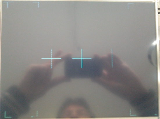
    I appreciate the feedback. I followed the recommendations made and the ghosts images have left, "locations/offsets". I add the image of what I see.

    What do you suggest?. The problem is linked to the frame buffer?

    Regards

    Jose

  • Hello Jose,

    Thanks for that - we've worked (designed/sold) w/such displays for years - should be able to solve your issue.  Following are my comments - all based from your (just arrived) photo:

    a) the "screen-centered" perpendicular bi-sector appears "dead center" signaling that your understanding of the display addressing and signal delivery is quite correct.  We note a (reasonably complete) ghost image perhaps 1 or 2 rows down and shifted left by ~25/125mm upon my viewing screen.  As 640 pixels reside in that 125mm we have the proportion 640/125 = ~5.12 pix/mm.  Thus 25 (pixel offset) * 5.12 pixels (per mm) yields a ghost image offset (to the left) of ~128 pixels. 

    We note also a (rather strange) ghost vertical bar - this offset right by nearly the same pixel separation.  And we note both the rather complete ghost image and the vertical bar both have broken/discontinuous, vertical presentation.  (i.e. missing pixels)

    b) Your targeted left, top (24,24) bisector appears improperly located.  I base that upon the lack of symmetry between screen edge and the bisector's intersection.  And at least 2 ghost images reveal (I was hoping for such) although the apparent "mirror imaging" and "lack of the horizontal "T" disturbs.  My instruction appears to have been unclear - desired was a vertical bisector reaching to the very top of the screen and horizontal line of like, 48 pixels.  (this would better reveal any ghost's offset)  Again both hor & vert are 48 pixel lines.

    c) Your targeted right, bottom (616,456) appears to have missed its mark.  (we'd expect to see a solid "T" symmetrically placed 24 pixels in from the right, bottom of screen.  We do not - only a short, horizontal line appears w/in that near vicinity.

    At this stage - while awaiting factory, "MCU specific" comment (that's not my domain) may I ask that you confirm the correct generation and placement of the bisectors targeted for both left/top & right/bottom?  If those were in fact drawn & located properly - big clue has emerged.

    If the factory cannot quickly resolve (weekend now arrives) perhaps you may repaint those screen images - this time with a (better described) 48 pixel mix of horiz & vert perpendicular bisectors - centered upon those exact screen locations.  (i.e. 24,24 "offset" locations from screen edges)

    I realize that you don't know me/my firm - and that my method differed greatly from factory line - and produced "no official comment." And - still you responded.  (perhaps "any" fireman looks good - when your house is afire!)

    As a premature (neck stuck out) SWAG (some slight science) you may have an address bus, signal short between address lines which are 128 pixels separated.  (i.e. believe that's 7 address lines separated such as A0 & A7 or A5 & A12.)  Also it's possible that signal integrity is not good - that an address line is open.  (less likely)

    That's my diagnosis - w/near zero knowledge of your MCUs TFT handling - but much TFT/LCD "under the belt."  (and just maybe - some slight diagnostic skill/desire...)

  • Yet one more quick thought, suggestion.  (could not get back into above post - for some forum reason...)

    Draw just 8, horizontal pixels - as close as possible - to the center of screen.  (i.e. 320,240 - 327,240)  Does a ghost appear?

    Then repeat, again 8 pixels but vertical this time - 320,240 - 320,247.  Does famed ghost appear?

    In each case log & report ghost's offset.

    If you can - then if the ghost does appear - reduce the pixel number to 4 and then 2.  Again check for ghosts.  We are seeking the determination, "does the ghost pixel arrive in "near synchronization" with the proper pixel?"  You'll have to do this slowly, carefully.  (not too easy to note a single pixel)  Do try to photograph - just one screen image at a time.

    Should ghosts reveal w/small number of pixels draw a single pixel to top/left screen coord. 0,0.  The ghost's offset from that screen location will immediately identify the magnitude of the (expected) ghost offset.  (and that's a very solid clue)

    Thanks.

  • Hello cb1,

    following the recommendations, I made the following tests:

    In any of the tests keep coming ghosts

    As for the evidence to draw a pixel at top left, I can tell that if a ghost appears, but in the right top at coordinates 0, 614 approx. As shown in the accompanying images.

    What do you think?

    Thanks again

    Regards

    Jose

  • Hello cb1,

    I appreciate the help you are giving me.

    I will continue with the recommendations. Also revise the address bus with the intention of discarding possible false contact or short that may be affecting the data arriving at the panel.

    We keep abreast of the results of tests on the address bus

    Regards

    Jose

  • I realize you're frustrated - note that last 2 photos have intense glare - tends to "mask" (camouflage) the ghost image.  Complicates our diagnosis.

    Also - can you go back to your last post (the most recent one) and, "Title each photo" with: Real Pixel intersection (then enter the targeted x,y coordinates) along with your best estimate/measurement of the "Ghost Pixel intersection or appearance.  (it must be that your view of the live image exceeds that posted here.

    Might it improve those photos if you position the camera above or below the display's viewing cone?  That should reduce (hopefully eliminate) the reflection of your hands and the camera.  You'll need to perform some experimentation there - possibly dim room-lights and operate w/out flash.

    In addition - perhaps your completion of this "template" will ease this exercise:

    Targeted Pixel Intersection                     Ghost Images Location

    0,0 (upper left of TFT)

    320,240 (exact center of TFT)

    640, 480 (bottom right of TFT)

    I don't think you've followed the creation of 16 pixel lines, intersecting midway thru both horiz & vert lines.  Here's what I was seeking:

     We need to detect if this intersect structure "breaks" as the ghost asserts.  I tried to communicate this via providing you the center coordinates of each line (vert & hor) with each line extending equal distances from that common center.  For example - as shown here, that point of intersection would be pixel (320,240) when we are targeting absolute screen center.

    Jose - I realize that TFT is expensive (I've visited that firm's factory many times) but your test of a 2nd set of hardware is always helpful.  (sometimes there is a single board issue - one errant solder "whisker" and such is difficult to detect and diagnose - especially as we're remote.  Such can be avoided thru use of a 2nd (or 3rd) board, component assembly. 

    Do ohm "out" the address bus connections - both @ MCU and TFT.  If this is not an MCU set-up/config issue - the (apparent) ghost offset's consistency points to a (possible) spurious write (after or preceeding) a valid one and/or the possible intrusion (via a pin/cable short) of a multi-plexed address line into a higher order (fixed) one.  (Say What?)  Good luck.

  • Ing. Jose Luis Ruiz said:

    What do you suggest?. The problem is linked to the frame buffer?

     Hi Jose, please can you measure vertical and Horizontal sync or if you use DE the relationship with these signal? Are dot clock in range?

     This ghost can also be generated by wrong sync.

     To determine if ram is in trouble try fill it with walking pattern or simply read back image area and display on a pc screen to see if ghost are on display or come from ram hardware fault.

     Another way can be try another LCD panel (one similar and one different resolution)  to see if similar issue appear or not.

  • Roberto Romano said:
    see if ghost are on display or come from ram hardware fault.

    I would bet you, Roberto that the consistency and similarity of ghost to real image, almost guarantees that the ghost has entered the display ram.  (frame buffer)

    You've repeated my suggestion to try a 2nd display.  (they're expensive, though)

    If poster can effectively "paint" the target cross-hairs @ display origin, dead center, and display end - do you still believe that this can be "sync" issue?  If so - might you detail?

  • cb1- said:
    I would bet you, Roberto that the consistency and similarity of ghost to real image, almost guarantees that the ghost has entered the display ram.  (frame buffer)

    This is right but not enough to say ram or display is defective, maybe none just software.

     I see no assignment on software project to a brand display, if 800x600 is selected a similar ghosted images appear and I bet this can be the trouble.

    cb1- said:
    do you still believe that this can be "sync" issue?  If so - might you detail?

     Yes and ghost is span from center can be due to wrong timing and adjustement...

  • Might you "detail" your belief of, "Sync" as cause?

    Roberto Romano said:
     Yes and ghost is span from center can be due to wrong timing and adjustement...

    That's little detail, Roberto - and as such may not be of great benefit to poster.

    If I can carve out the time - I'll prepare (and post here)  a graphic example which illustrates how an improper match of frame buffer "unload" (timing and extent) to the actual frame buffer - can yield a predictable (yet unwanted), "ghost image."

    As you/I know Roberto, devil so often lurks in such detail...  (yet to be presented - this thread...)

  • [edit 15:07, 01 July '14]  Plz go to post just below - logged @ 15:06, this date - "if" a scope is available...(suggest that you read - follow suggestions there - then return here...)

    Have made the time to find/download the special font required to fully/properly read/review your TFT spec.  This effort will be greatly eased if you have or can locate/borrow a reasonable scope.  Hope you can...

    This panel employs its, "ENAB" signal as a central display control element.  (this from the TFT's timing chart - Pg 9)  "Input Timing Characteristics" (8.5) reveals that ENAB must be ordered high throughout the entire time period in which your RGB data is being clocked in.  (i.e. 640 such data clocks)

    I'd ask if your MCU provides a signal competent to meet 8.5's timing specification?  (you'll have to read/review the MCU spec - our group has little knowledge of your MCU)  (we use many ARMs - many vendors)

    Adding an always delightful "twist" to deadman's curve - item (1) suggests that ENAB may be fixed "Low" - and that the display then starts from the data of C104(clock)!  (Say What?)  Might this explain your plight?  You must review the MCU spec and use of a scope will determine if ENAB is present - accounted for.  (and proper)

    If ENAB is present - read on...

    To heighten your understanding of this 8.5 chart - and to confirm the correctness of your "writes" to the TFT - I present the following.  You will need a reasonable scope to perform these measurements/signal verifications...Trick here (I feel) is to, "much clarify the sequence & measurement of needed signals" - which remains muddy/abstract (for many) when reviewing the "naked" display timing chart. 

    Our method requires that you write a single, saturated color to pixels, D1, DH1 & D3, DH3.  (leaving D2, DH1 set to 0.)  By saturated we mean all Red or all Green or all Blue - no color mix.  (i.e. all bits w/in that pixel, that color, set)

    Then apply the same saturated pixel to D639, DH1 & D640, DH1.  This must be done after "clearing the screen" - so that no pixels reveal.  These writes are strategic in that they serve as effective "markers" announcing the very beginning and the end of the TFT's row 1.  (top row)  This is important as you may then employ a 2 channel scope to view both these marker bits and the critical ENAB signal.  All bits should fit w/in - yet very close to the edges of ENAB - while ENAB is high.

    If this test/verifies you may repeat using TFT row DH480 (bottom row) (left for the reader is the parallel calculation of those pixel locations)  Note that there is a deliberate difference between left & right markers - so that any unfortunate shifting/transposition may be noted.

    Believe this to be the most fertile area for you to next explore.  If this checks out - we can move on to the V & H Sync - although Amit has earlier confirmed that most of your screen's MCU settings were correct.

    A clear, hi-contrast (glare minimized) photo would assist greatly.  Again position the camera above or below the viewing cone of your scope to minimize reflections.  If possible dim room lights - avoid flash.  (We're told that Spielberg may be available...)

  • "Troubleshooting a (likely) TFT timing issue when a 2 channel (better a 4 ch.) scope is available..."

    Following is my best effort after read/review of subject TFT data sheet - Pg 9, 8.5 Input timing characteristics:

    Start after MCU is properly initialized - your TFT code is running - I'd start with simple cross-hair, @ screen center - as past described/detailed...

    a) Scope the TFT clock input: should be 22-27MHz and arrive (clean edged) @ TFT pin 39.  Report/photo.

    b) Scope both the H-Sync & ENAB (38, 14 TFT).  ENAB should "fit" entirely w/in H-Sync's "high" time.  Set trigger on h-sync's rising edge. Both signals should transition high during this period.  H_Sync's period should be ~800 clocks.  Report/photo.

    c) Scope both V-Sync & ENAB (37, 14).  480 ENAB "high" should be viewed w/in V-sync "high" period.  V-Sync's period should be 525 display lines.  Report/confirm/photo.

    Above records the general correctness of MCU to TFT signal generation.  If present/proper - we now move to critical timing:

    d) Scope both H-Sync and ENAB.  Trigger on H-Sync rising edge.  ENAB should follow H-Sync rise by no fewer than 44 clock periods.  (recall clock @/around 25MHz,  math left to reader)

    e) Scope ENAB - should remain high for 640 clock periods.

    f) Scope H-Sync - should go low for ~96 clock periods.

    g) Scope V-Sync - should go low for 2-34 display "lines."  (line = ~800 clock periods)

    h) Scope both V-Sync & ENAB.  Trigger on V-Sync falling edge.  ENAB should drive high 34 "line periods" after V-Sync's falling edge

    These measurements will indicate the degree of compliance between your MCU (under your set-up/config SW) and your TFT.  Highlight any differences you discover - take good (i.e. no reflections, high contrast) photos so that your sleep deprived, seaward bound - anticipatory - USA, holiday bound celebrants have, "some chance" to "see - review."  

  • cb1- said:

    Might you "detail" your belief of, "Sync" as cause?

     Hi CB, when sync front porch, back porch, sync duration or frequency are out of range some strange behaviour appear. The front and back porch  are also known as phase and do some shift left or right to image and when too much close to image sometimes create similar issue.

     When frequency is not matched some multiple (ghost) images are on screen and sometimes flicker. I remember an issue very close to the one in picture, all hardware where ok other than vertical horizontal timing.

     Poster checked your answer as verified so I suppose issue where coming from some soldering issue or other we are glad to know, yes also an address line can generate similar trouble, another good test is to move start of frame buffer half line size forward to see if image react differently.

     Maybe in the future return there and I post an image showing what it appear on wrong parameter.

     I don't know in deep controller, can be we can meet again this topic, I stopped again production to when I am sure have silicon. PCB sampling cost a fortune and I cannot repeat again same error from Stellaris age, SDram is connected to FPGA EPI shared so maybe LCD controller got the IPCore way avoiding multiport arbitration, TIVA is still in learning and now my time is too much limited.

  • @Roberto,

    Our posts just crossed - I was writing, "from the air" lost forum many times.

    Devil is in the details - I've provided the poster a rather exact method to measure critical signals.  Minus the needed detail - we'll be here forever - pretty gurl (unskilled/unruly crue) & sailboat sound way more fun...  (July 4 - 4 day holiday calls to cb1)

    Our group has designed/developed/sold 100K+ such displays - analysis here should prove sound/supportable.  I've no comment upon user's/vendor's MCU in this regard.  We've chosen another - doubtful we'll hoist any 129 pennant - our sleek, "pirate" vessel anytime soon...

  • cb1- said:
    Devil is in the details - I've provided the poster a rather exact method to measure critical signals.  Minus the needed detail - we'll be here forever - pretty gurl (unskilled/unruly crue) & sailboat sound way more fun...  (July 4 - 4 day holiday calls to cb1)

     Just to see what happen, on mid of July (or when sample arrive)  can be I load this project on my DK board then attach Logic analyzer inspecting in detail what happen on LCD port, I dont own a similar panel but mine 5" Tiamna 480x272 has very similar timing and test bed can serve troubleshoot both.

  • I believe that each/every 480x272 requires clock very close to 16MHz.  As stated - poster's may be good 10MHz higher.

    As always - only thing standard about Displays - "There is NO Standard!"

  • cb1- said:

    I believe that each/every 480x272 requires clock very close to 16MHz.  As stated - poster's may be good 10MHz higher.

     http://www.tianma-europe.com/downloads/tm050nbh01-00_prelininary_v0-1.pdf

     Typical 9MHz@24bit 27MHz@8bit, target is not to use large quantity of pin so 8 bit ca be the solution...

     Before to do any other test I wish see TIVA part as available, otherwise IPCore can suit better NOW!


  • @Roberto - of course your 4.3/5.0 @ 480x272 is 9MHz.  (what was I thinking?)  But - stand (more firmly) behind laundry list of detailed checks/measures for poster's enjoyment.  Some way/how seems superior to "improper sync!"

    @ Jose - I've looked at your SDRAM and note that A10 may require, 'special treatment" as it has a, "pre-charge role."  Might that be a cause agent in your ghosting - if that A10 "special" was missed or not correctly managed?

    I looked at your "main.c" - I could not tell if you directed the code toward LXD - which I think duplicated your 640x480 resolution.  (double check me - LXD may have been 800x480)

    The code for that "129" is far outside our interest - we've chosen a different TFT method - cannot afford time/effort on that which we believe to be, "lesser performer."  At the minimum you should read/review the MCU manual - especially keying upon any timing charts - and see how & if they "match" that of your TFT.  My earlier post lists all of the critical signals and their timing relationships - your job now is to methodically examine each - see if they match...

    Should timing violations reveal - return to the MCU manual - see if the MCU can be forced into compliance w/the TFT.  MCU is (or should be) bit "bendable" - TFT panels are not!

    I could find no schematic highlighting MCU - SDRAM - and TFT.  That would help - would it not?  Especially of note would be handling of A10...

  • Hello cb1,

    Following the recommendations I have reviewed connections to the RAM to rule out any problems in Hardware, I commented that no short circuit and open lines in connection with the MCU.

    I will continue doing other than recommended before sending unsolicited photos with coordinates tests.

    Regards

    Jose

  • @Jose,

    That A10 "precharge" role w/in your SDRAM concerns.  Should this MCU (or any MCU/FPGA) driving an external Frame Buffer - not have fully/properly anticipated - that alone may be cause of your ghost issues.

    Thanks for checking connections (could not hurt) and use of a 2nd display would tend to rule out a "display" issue.

    Again a schematic - especially detailing handling & connection of SDRAM A10 - would be of much interest...

  • Hello cb1,

    Following the suggestions above, I am adding some pictures of the signals as listed below:

    a) Scope the TFT clock input: should be 22-27MHz and arrive (clean edged) @ TFT pin 39.  Report/photo.

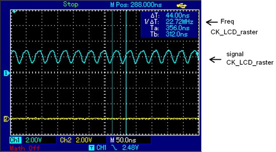
    The following image depicts the "CK", the culál signal is within the range indicated by the data sheets TFT, although the signal is not square, it meets the frequency range of 22.72Mhz.

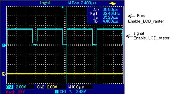
    The "enable" signal is in the range indicated by the data sheets, complying with "Tep" 640 clock. 22.72Mhz / 640 = 35.5Khz. The captured signal "enable" it has a frequency of 32.46Khz, I think it is in the range, you think?

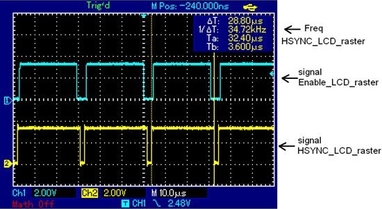
    b) Scope both the H-Sync & ENAB (38, 14 TFT).  ENAB should "fit" entirely w/in H-Sync's "high" time.  Set trigger on h-sync's rising edge. Both signals should transition high during this period.  H_Sync's period should be ~800 clocks.  Report/photo.

    Using the oscilloscope captured the "enable" signals and "Hsync" to be sure that it meets specified in data sheets. The "Hsync" signal lasts slightly longer in high level signal "enable" a frequency 34.72Khz

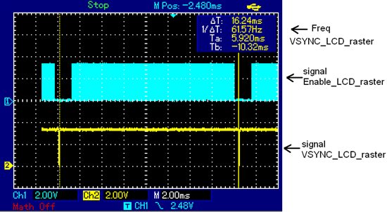
    c) Scope both V-Sync & ENAB (37, 14).  480 ENAB "high" should be viewed w/in V-sync "high" period.  V-Sync's period should be 525 display lines.  Report/confirm/photo.

    Using the oscilloscope captured the "enable" signals and "Vsync" to be sure that it meets specified in data sheets. The "Vsync" high level signal lasts for 16.24mS time corresponding to a frequency of 61.57Hz. Considering that "what must be Vsync aporx 525 lines, this gives us 525 = 61.57Hz * 32.32Khz, is close to the frequency of the signal" enable "which is 32.46Khz. Seems that I'm within range, no But if you have a comment I appreciate your comments.

    I will continue doing tests performed make suggestions. Thank you and we keep in touch.

    I appreciate your help

    regards

    Jose

  • Ing. Jose Luis Ruiz said:

    Following the suggestions above, I am adding some pictures of the signals as listed below:

     Hi Jose, timing seems as OK, what happen if you change base RAM address to display controller?

  • Roberto's faster than me in read/review of your scope caps.  As 3 weeks have passed - I'm bit stale on where we were - where left off.  Give me day/two for proper review.  (we have big product demo scheduled for tomorrow)

    Do note that A10 - flagged twice - remains silent!   You may wish to re-read - provide some commentary in that regard.  (my belief - anything "disturbing" the normal/customary memory address scheme is, "Highly suspect!")

  • Hi Roberto,

    I commented that following your recommendations for testing changing locality in SDRAM, I discovered I had bad instruction, because instead of indicating that size is 32MB, indicating it was as if the memory was 64MB. With this change have disappeared "ghosts". Schedule a picture of how it looks now.

    I appreciate all the advice and tips, which were very important to rule out hardware problems SDRAM and LCD controller. In the end, the problem was associated with the software, with stage settings for the SDRAM.

    Thank´s

    Jose

  • Hi cb1,

    I appreciate all the advice and tips, which were very important to rule out hardware problems SDRAM and LCD controller. In the end, the problem was associated with the software, with stage settings for the SDRAM.

    Thank´s

    Jose

  • Hi Jose,

    We are also facing the similar issue in our setup as in the below e2e link.

    e2e.ti.com/.../1775643

    Could you please indicate what is the exact change done in SDRAM settings to solve this issue ?
  • Hello Prashanth

    Are you using a external SDRAM? If yes, then which one and what is the configuration code?

    Regards
    Amit
  • Yes. We are using external SDRAM W9816G6JH-6I(from winbond), which is 512K x 2 banks x 16-bits SDRAM(i.e. total size of 2 MB). For the sdram configuration, we are using the same file which is available as "sdram.c" inside raster_example".