This thread has been locked.

If you have a related question, please click the "Ask a related question" button in the top right corner. The newly created question will be automatically linked to this question.

SPI problems with interruptions

Greetings, im using a TM4C123GXL launchpad and the problem is the next.

Im trying to use the RXFF and TXFF interrupts to send and receive, but one of them is not executing very well,  It can't identify the interrupt.

ulStatus doesn't get in the 0x04 (RXFF). I can't find the problem, it can't execute the interruption for RXFF. probably i dont undertand how it starts this interrupt.


#include <stdbool.h>
#include <stdint.h>
#include "inc/hw_gpio.h"
#include "inc/hw_ints.h"
#include "inc/hw_nvic.h"
#include "inc/hw_memmap.h"
#include "inc/hw_types.h"
#include "driverlib/debug.h"
#include "driverlib/fpu.h"
#include "driverlib/gpio.h"
#include "driverlib/interrupt.h"
#include "driverlib/pin_map.h"
#include "driverlib/rom.h"
#include "driverlib/pwm.h"
#include "driverlib/sysctl.h"
#include "driverlib/systick.h"
#include "driverlib/uart.h"
#include "utils/uartstdio.h"
#include "driverlib/buttons.h"
#include "driverlib/adc.h"
#include "driverlib/timer.h"
#include "math.h"
#include "driverlib/ssi.h"
#include "driverlib/qei.h"

//*****************************************************************************
//
// Number of bytes to send and receive.
//
//*****************************************************************************
#define NUM_SSI_DATA 3

//*****************************************************************************
//
// Global variables used in interrupt handler and the main loop.
//
//*****************************************************************************
volatile unsigned long g_ulSSI2RXFF = 0, g_ulSSI2TXFF = 0;
uint32_t g_ulDataRx2[NUM_SSI_DATA];
uint32_t g_ulDataTx2[NUM_SSI_DATA];
int count;
//ADC
unsigned long canal_0_adc0, canal_1_adc0, canal_2_adc0, canal_3_adc0, canal_5_adc0; // ADC variables
uint32_t ulADC0Value[5];
uint32_t g_ulDataRx0[NUM_SSI_DATA];
uint32_t g_ulDataTx0[NUM_SSI_DATA];
//*****************************************************************************
//
// Interrupt handler for SSI2 peripheral in slave mode. It reads the interrupt
// status and if the interrupt is fired by a RX time out interrupt it reads the
// SSI2 RX FIFO and increments a counter to tell the main loop that RX timeout
// interrupt was fired.
//
//*****************************************************************************
void
SSI2IntHandler(void)
{
unsigned long ulStatus, ulIndex;

//
// Read interrupt status.
//
ulStatus = SSIIntStatus(SSI2_BASE, 1);
//
// Check the reason for the interrupt.
//
if(ulStatus & SSI_TXFF)
{
//
// Interrupt is because of RX time out. So increment counter to tell
// main loop that RX timeout interrupt occurred.
//
g_ulSSI2TXFF++;

//
// Read NUM_SSI_DATA bytes of data from SSI2 RX FIFO.
//
for(ulIndex = 0; ulIndex < NUM_SSI_DATA; ulIndex++)
{

SSIDataGet(SSI2_BASE, &g_ulDataRx2[ulIndex]);

}
SSIIntClear(SSI2_BASE, SSI_TXFF);
SSIIntDisable(SSI2_BASE, SSI_TXFF);
}

if(ulStatus & SSI_RXFF)
{

//
// Interrupt is because of RX time out. So increment counter to tell
// main loop that RX timeout interrupt occurred.
//
g_ulSSI2RXFF++;


//
// Read NUM_SSI_DATA bytes of data from SSI2 RX FIFO.
//
for(ulIndex = 0; ulIndex < NUM_SSI_DATA; ulIndex++)
{
SSIDataPut(SSI2_BASE, g_ulDataTx2[ulIndex]);

}
SSIIntClear(SSI2_BASE, SSI_RXFF);
SSIIntDisable(SSI2_BASE, SSI_RXFF);
}
//
// Clear interrupts.
//
//SSIIntClear(SSI2_BASE, ulStatus);


}

void
InitConsole(void)
{
//
// Enable GPIO port A which is used for UART0 pins.
//
SysCtlPeripheralEnable(SYSCTL_PERIPH_GPIOA);

//
// Configure the pin muxing for UART0 functions on port A0 and A1.
// This step is not necessary if your part does not support pin muxing.
//
GPIOPinConfigure(GPIO_PA0_U0RX);
GPIOPinConfigure(GPIO_PA1_U0TX);

//
// Select the alternate (UART) function for these pins.
//
GPIOPinTypeUART(GPIO_PORTA_BASE, GPIO_PIN_0 | GPIO_PIN_1);

//
// Initialize the UART for console I/O.
//
UARTStdioConfig(0, 115200, 80000000);
}

void
InitSPI0(void)
{
//
// The SSI0 peripheral must be enabled for use.
//
SysCtlPeripheralEnable(SYSCTL_PERIPH_SSI0);

//
// For this example SSI0 is used with PortA[5:2]. GPIO port A needs to be
// enabled so these pins can be used.
//
SysCtlPeripheralEnable(SYSCTL_PERIPH_GPIOA);

//
// Configure the pin muxing for SSI0 functions on port A2, A3, A4, and A5.
// This step is not necessary if your part does not support pin muxing.
//
GPIOPinConfigure(GPIO_PA2_SSI0CLK);
GPIOPinConfigure(GPIO_PA3_SSI0FSS);
GPIOPinConfigure(GPIO_PA4_SSI0RX);
GPIOPinConfigure(GPIO_PA5_SSI0TX);

//
// Configure the GPIO settings for the SSI pins. This function also gives
// control of these pins to the SSI hardware. Consult the data sheet to
// see which functions are allocated per pin.
// The pins are assigned as follows:
// PA5 - SSI0Tx
// PA4 - SSI0Rx
// PA3 - SSI0Fss
// PA2 - SSI0CLK
//
GPIOPinTypeSSI(GPIO_PORTA_BASE, GPIO_PIN_5 | GPIO_PIN_4 | GPIO_PIN_3 |
GPIO_PIN_2);

//
// Configure and enable the SSI0 port for SPI master mode.
//
SSIConfigSetExpClk(SSI0_BASE, SysCtlClockGet(), SSI_FRF_MOTO_MODE_2,
SSI_MODE_MASTER, 660000, 16);

//
// Enable the SSI0 module.
//
SSIEnable(SSI0_BASE);
}

void
InitSPI2(void)
{
//
// The SSI0 peripheral must be enabled for use.
//
SysCtlPeripheralEnable(SYSCTL_PERIPH_SSI2);

//
// For this example SSI2 is used with PortH[7:4]. GPIO port H needs to be
// enabled so these pins can be used.
//
SysCtlPeripheralEnable(SYSCTL_PERIPH_GPIOB);

//
// Configure the pin muxing for SSI2 functions on port H4, H5, H6 and H7.
// This step is not necessary if your part does not support pin muxing.
//
GPIOPinConfigure(GPIO_PB4_SSI2CLK);
GPIOPinConfigure(GPIO_PB5_SSI2FSS);
GPIOPinConfigure(GPIO_PB6_SSI2RX);
GPIOPinConfigure(GPIO_PB7_SSI2TX);

//
// Configure the GPIO settings for the SSI pins. This function also gives
// control of these pins to the SSI hardware. Consult the data sheet to
// see which functions are allocated per pin.
// The pins are assigned as follows:
// PH7 - SSI2Tx
// PH6 - SSI2Rx
// PH5 - SSI2Fss
// PH4 - SSI2CLK
//
GPIOPinTypeSSI(GPIO_PORTB_BASE, GPIO_PIN_7 | GPIO_PIN_6 | GPIO_PIN_5 |
GPIO_PIN_4);

//
// Configure and enable the SSI2 port for SPI slave mode.
//
SSIConfigSetExpClk(SSI2_BASE, SysCtlClockGet(), SSI_FRF_MOTO_MODE_2,
SSI_MODE_SLAVE, 660000, 16);

//
// Enable the SSI2 module.
//
SSIEnable(SSI2_BASE);
}

void
ADCRead (uint32_t ulADC0Value[]){

ROM_ADCSequenceDisable(ADC0_BASE, 0);

ROM_ADCSequenceConfigure(ADC0_BASE, 0, ADC_TRIGGER_PROCESSOR, 0); // Maximum priority

ROM_ADCSequenceStepConfigure(ADC0_BASE, 0, 0, ADC_CTL_CH0); // PE3 - canal 0
ROM_ADCSequenceStepConfigure(ADC0_BASE, 0, 1, ADC_CTL_CH1); // PE2 - canal 1
ROM_ADCSequenceStepConfigure(ADC0_BASE, 0, 2, ADC_CTL_CH2); // PE1 - canal 2
ROM_ADCSequenceStepConfigure(ADC0_BASE, 0, 3, ADC_CTL_CH3); // PE0 - canal 3
ROM_ADCSequenceStepConfigure(ADC0_BASE, 0, 4, ADC_CTL_CH5 | ADC_CTL_IE | ADC_CTL_END); // PD2 - canal 5

ROM_ADCSequenceEnable(ADC0_BASE, 0); //Enable Sequence0

ROM_ADCIntClear(ADC0_BASE, 0); // Clear ADC flag

ROM_ADCProcessorTrigger(ADC0_BASE, 0); //Trigger ADC in the processor

while(!ROM_ADCIntStatus(ADC0_BASE, 0, false)) {/*wait for conversion*/}

ROM_ADCSequenceDataGet(ADC0_BASE, 0, ulADC0Value); // Data to buffer

canal_0_adc0 = (ulADC0Value[0]); // Throttle
canal_1_adc0 = (ulADC0Value[1]); // Current sensor
canal_2_adc0 = (ulADC0Value[2]); // Axis X
canal_3_adc0 = (ulADC0Value[3]); // Axis Y
canal_5_adc0 = (ulADC0Value[4]); // Axis Z

}

void
Send (uint32_t ulDataTx0[]) {

unsigned long ulindex;

// Clear any pending interrupt
//
SSIIntClear(SSI2_BASE, SSI_TXFF);

UARTprintf("\n Sent:\n ");

for(ulindex = 0; ulindex < NUM_SSI_DATA; ulindex++)
{

UARTprintf("'%d' ", ulDataTx0[ulindex]);
SSIDataPut(SSI0_BASE, ulDataTx0[ulindex]);
}

while(SSIBusy(SSI0_BASE))
{

}

SSIIntEnable(SSI2_BASE, SSI_TXFF );

IntEnable(INT_SSI2);

//
// Wait for the SSI2 RXTO interrupt to fire and data read from RXFIFO.
//
while(g_ulSSI2TXFF == 0)
{
}
//
// Display indication that salve has receiving data.
//
UARTprintf("\nReceived:\n ");

//
// Display the 3 bytes of data that were read from RX FIFO.
//
for(ulindex = 0; ulindex < NUM_SSI_DATA; ulindex++)
{
UARTprintf("'%d' ", g_ulDataRx2[ulindex]);
}
SSIIntClear(SSI2_BASE, SSI_TXFF);
//SSIIntDisable(SSI2_BASE, SSI_TXFF);

}

void
Ask (void){

//uint32_t ulDataRx0[NUM_SSI_DATA];
unsigned long ulindex;

SSIIntClear(SSI2_BASE, SSI_RXFF);

UARTprintf("\n Asked:\n ");

SSIIntEnable(SSI2_BASE, SSI_RXFF );

IntEnable(INT_SSI2);

//
// Send 3 bytes of data.
//

for(ulindex = 0; ulindex < NUM_SSI_DATA; ulindex++)
{
SSIDataGet(SSI0_BASE, &g_ulDataRx0[ulindex]);
}

while(SSIBusy(SSI0_BASE))
{

}

//
// Wait for the SSI2 RXTO interrupt to fire and data read from RXFIFO.
//
while(g_ulSSI2RXFF == 0)
{
UARTprintf("wait\n");
}


for(ulindex = 0; ulindex < NUM_SSI_DATA; ulindex++)
{
UARTprintf("'%d' ", g_ulDataRx0[ulindex]);
}

SSIIntDisable(SSI2_BASE, SSI_TXFF | SSI_RXFF);


}


int
main(void)
{
uint32_t ulDataTx0[NUM_SSI_DATA];
uint32_t ulDataRx0[NUM_SSI_DATA];

//
// Set the clocking to run directly from the external crystal/oscillator.
ROM_SysCtlClockSet(SYSCTL_SYSDIV_2_5|SYSCTL_USE_PLL|SYSCTL_XTAL_16MHZ|SYSCTL_OSC_MAIN);

ROM_SysCtlPeripheralEnable(SYSCTL_PERIPH_GPIOE);
ROM_SysCtlPeripheralEnable(SYSCTL_PERIPH_GPIOD);
ROM_SysCtlPeripheralEnable(SYSCTL_PERIPH_ADC0);

ROM_FPULazyStackingEnable();
ROM_FPUEnable();

// Configurar ADC_0

ADCClockConfigSet(ADC0_BASE, ADC_CLOCK_SRC_PIOSC | ADC_CLOCK_RATE_HALF, 1); //
ROM_ADCHardwareOversampleConfigure(ADC0_BASE, 64); // 64 samples for each value
//
// Set up the serial console to use for displaying messages. This is
// just for this example program and is not needed for SSI operation.
//

InitConsole();

//
// Display the setup on the console.
//
UARTprintf("SSI ->\n");
UARTprintf(" Mode: SPI\n");
UARTprintf(" Data: 16-bit\n\n");

//
// Init SPI0 as master.
//
InitSPI0();
//
// Init SPI2 as slave.
//
InitSPI2();

//
// Read any residual data from the SSI port. This makes sure the receive
// FIFOs are empty, so we don't read any unwanted junk. This is done here
// because the SPI SSI mode is full-duplex, which allows you to send and
// receive at the same time. The SSIDataGetNonBlocking function returns
// "true" when data was returned, and "false" when no data was returned.
// The "non-blocking" function checks if there is any data in the receive
// FIFO and does not "hang" if there isn't. This might not be needed here.
//
while(SSIDataGetNonBlocking(SSI0_BASE, &ulDataRx0[0]))
{
}
//
// Enable RX timeout interrupt.
//
//SSIIntEnable(SSI2_BASE, SSI_TXFF);

//
// Read any residual data from the SSI port. This makes sure the receive
// FIFOs are empty, so we don't read any unwanted junk. This is done here
// because the SPI SSI mode is full-duplex, which allows you to send and
// receive at the same time. The SSIDataGetNonBlocking function returns
// "true" when data was returned, and "false" when no data was returned.
// The "non-blocking" function checks if there is any data in the receive
// FIFO and does not "hang" if there isn't.
//
while(SSIDataGetNonBlocking(SSI2_BASE, &g_ulDataRx2[0]))
{
}

//
// Clear any pending interrupt
//
SSIIntClear(SSI2_BASE, SSI_TXFF | SSI_RXFF);
SSIIntDisable(SSI2_BASE, SSI_TXFF | SSI_RXFF);

while(1)
{

ADCRead(ulADC0Value);

ulDataTx0[0] = ulADC0Value[0];
ulDataTx0[1] = count++;
ulDataTx0[2] = 46;

Send(ulDataTx0);

g_ulDataTx2[0] = 1;
g_ulDataTx2[1] = 2;
g_ulDataTx2[2] = 3;

Ask();

SysCtlDelay(10000000);


}
}

It get's stuck in the wait

  • Hello Victor,

    The issue seems to be in the interrupt handler. In the TXFF condition the Data is being read out. So it is possible that the RX FIFO never reaches the threshold

    for(ulIndex = 0; ulIndex < NUM_SSI_DATA; ulIndex++)
    {

    SSIDataGet(SSI2_BASE, &g_ulDataRx2[ulIndex]);

    }

    Regards

    Amit

  • 7444.SSIloopback1.rar

    Sending the project if you need to check anything.

    My problem is when RXFF is occuring and when should i activate the interruption.

    I've tried like this:

    SSIIntEnable(SSI2_BASE, SSI_RXFF);

    IntEnable(INT_SSI2);

    for(ulindex = 0; ulindex < NUM_SSI_DATA; ulindex++)
    {
    SSIDataGet(SSI0_BASE, &g_ulDataRx0[ulindex]);
    }

    while(SSIBusy(SSI0_BASE))
    {
    }

    while(g_ulSSI2RXFF == 0)
    {
    }

    enabling the interrupt before i make dataget, and also tried:

    for(ulindex = 0; ulindex < NUM_SSI_DATA; ulindex++)
    {
    SSIDataGet(SSI0_BASE, &g_ulDataRx0[ulindex]);
    }

    while(SSIBusy(SSI0_BASE))
    {
    }

    SSIIntEnable(SSI2_BASE, SSI_RXFF);

    IntEnable(INT_SSI2);

    while(g_ulSSI2RXFF == 0)
    {
    }

    None of those situations made the RXFF start.

  • Hello Victor,

    You can activate the interrupt in the main Initialization code. Whenever the data comes to the Slave and the FIFO is half or more full, then you would get the interrupt.

    But you also have the TXFF condition in which you read the data from RX FIFO. That condition is not correct.

    Regards

    Amit

  • 5148.SSIloopback2.rar

    Finally its working, but i noticed something strange. 

    The information im getting have a delay. What i mean is, The first send is received in the second received.

    And in the Master asking the slave its 3 communication cycles. Is it normal or there is a solution?

  • Hello Victor,

    Do you mean when the Master sends one word to the Slave, the Slave asserts the interrupt during the Second Receive word?

    A simple time graph of the transaction on the serial interface and when the CPU reads it from the Slave buffer would be useful

    Regards

    Amit

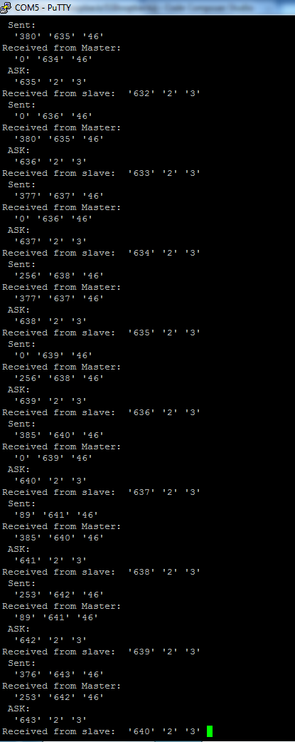
  • Here's the result.

    Send: Master sending to slave.

    Received from Master: Slave receiving.

    Ask: Master asking data from slave.

    Received from slave: Master received data 

    Nitice that, data send to slave is 1 cycle of delay (second number).  and the ask is 3 cycles late (first number e other counter).

    I can't supply that time graph or at least i dont now how.

  • Hello Victor

    That does the job. Would need some time to understand the code and why the delay is happening.

    Regards

    Amit

  • Hello Victor,

    Yes, the code has an issue. Attached is the updated project for the Send() Issue

    5047.SSIloopback.7z

    Let me explain it. The Master Sent the data but the Slave which requires half FIFO to be full will not send the receive interrupt as only 3 units are being sent. I rather use the Receive Timeout for the Slave to send an interrupt for the data to be read.

    As for the Ask function, who is supposed to initiate the Ask packet?

    Regards

    Amit

  • The ask packet is supposed to be iniciated by the Master. He makes a DataGet() to trigger the Slave to DataPut() into the FIFO.

    Well after your ajustments i've managed to improve my program that the send doesn't delay and the ask only delays 1 cycle.

    Your solution of RXTO to send is working perfectly.

    I've put instead of NUM_SSI_DATA = 3, an 8 so it can detect FIFO more then half. Even so i dont know why the Ask is 1 cycle delay.

    Still pretty good result so far.

  • Hello Victor,

    The SSI Master has to do a SSIDataPut to get data. I believe the code is seeing artifacts of previous transmission because of which you are seeing 1 cycle delay.

    If you can send the updated code, I can help fix it as well on the Ask, by late this next week.

    Regards

    Amit

  • I'm already working on seperated codes, Master code and Slave code.

    I can put it on project and send you to analysis, but im gonig to keep working on them like they are.

    1832.MASTERSLAVE_seperate.rar

  • Hello Victor,

    Fair enough and right enough. What you need to make sure is that when the SSI master has to get data then it has to push data to generate the CLK and FSS.

    Regards

    Amit

  • Hello Amit,

    Returning to the communication, i thought that my communication problems were all solved, but its not, at my final version of the code, i can't manage to execute the Ask() function to get the speed from the slave microcontroller.

    Last time i said there was a delay in my FIFO reception of Master of about 3 cycles. I dont know if that's what is getting me into trouble.

    The code is in my last post, you will need 2 tivas conected like:

    PA2 - PA2

    PA3 - PA3

    PA5 - PA4

    PA4 - PA5

    If you can find the problem of the delay, i may try to implement the fix on my new code, or the problem will be my new code unfortunatly. 

    I checked that the problem is the interrupt in the slave. Somehow my master is not triggering the Slave in my new code, and i just added other diferent functions, nothing to do with the SSI communication.

  • Hello Victor,

    As I mentioned earlier, the delay was an artifact of the coding of the loop.

    Did you check the Errata and Datasheet for SSI. There is a known issue with interrupt for SSI Slave.

    Regards

    Amit

  • Ok, i found my possible problem, but i can't find the solution.

    I probably have to add to my code the comand:

    while(SSIDataGetNonBlocking(SSI0_BASE, &ulDataRx0)){}

    and the 

    while(SSIDataPutNonBlocking(SSI0_BASE, &ulDataTx0)){}

    but i dont know when or where.

    somehow the Ask() function is only 1 cycle late, but the slave now doesn't receive the values right. I still have a few configurations to attempt.

  • Hello Victor.

    If it still does not work, then post the updated CCS project and I would try checking what is happening next week.

    Regards

    Amit

  • Greetings, i've been doing some fixes and the best i could in 1 version (Mas-Slave only communication) was to reduce the slave to master delay communication from 3 cycles to 2 cycles.

    In my main code no changes.

    i'll post both so you could check.

    My communication code, working:

    0218.SSI-Master-Slave.rar

    My main code not working

    5047.SSI-Master-Slave-complete.rar

    In my main, one of the first things i ask is the Ask() function that supposely triggers the interrupt in the Slave, but that's not happening. I've tried with RXFF and RXTO type.

    With RXFF, i can see the interrupt triggering but only makes 1x dataget from the cycle for and then freeezes.

    Well, anyway the problem is still in the communication code.

  • I found a problem in my main code, i was rewritting PA5 as a GPIO and its a SSI pin.

    Reworking the code again, still havent tested

  • 3323.SSI-Master-Slave_complete.rar

    This is my latest code, i had some things fixed or reordered

  • Hello Victor,

    There were some more issues

    1. In the Slave Code the timer interrupt has been enabled but the interrupt handler is missing in the startip_ccs.c file

    2. In the Master Code when sending Ask Command the existing code was

            SSIDataGet(SSI0_BASE, &g_ulDataRx0[ulindex]);

    whereas it should be

            SSIDataPut(SSI0_BASE, 0x00);

            SSIDataGet(SSI0_BASE, &g_ulDataRx0[ulindex]);

    The Master reads the RX line only when clocks are generated on the bus and FSS is low. For this to happen it has to write to the TX Buffer (even if it is dummy data).

    Lastly I am not sure, what should I make out of the console print that is happening!!! Can you send in an example print on both master and slave side and what corresponds to the transactions.

    Regards

    Amit

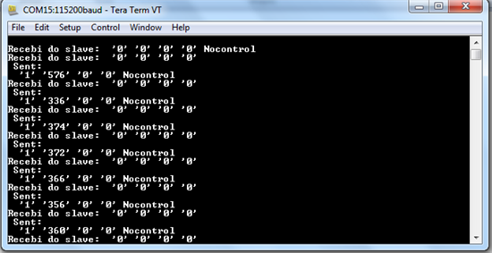
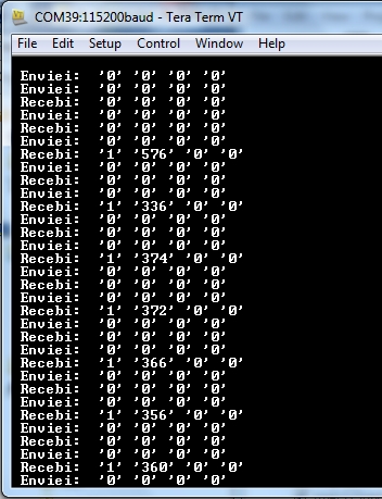
  • Recebi do slave = Received from slave

    Enviei = Sended

    Left values are the Master and Right one slave.

    This is the code with only the communication.

    It triggers twice. Because im using the Dataput commands, and it triggers an interrupt and when it find info, triggers again with the dataget.

    im gonna test my main code adding sme delays and check if its ok.

  • Hello Victor,

    I sure am not getting the data in the format that is shown. In fact for the Master and Slave it prints almost 6 strings. Are you sure that you have sent the correct files? Also I just have connected the SSI lines, Start the Slave first and then start the master. Is the sequence and connection right?

    Regards

    Amit

  • This is the SSI lines:

    PA2-PA2

    PA3-PA3

    PA4-PA5

    PA5-PA4

    The dataput made it work, but its triggering twice, and one of them is just sending 0's. Because i suposse when you put DataPut(SSI0_BASE, 0x00), your not putting CS low, but sending a string to trigger a interrupt in the salve, that for this case is a Rx communication, its kinda controversial.

    Somehow, i think that i need to use the DataPutNonBlock and DataGetNonBlock, in the code for communication, but i already tried and the results are not good.

  • Hello Victor,

    When communicating over SPI, we actually implemented a simple protocol where the communication between master and slave is done with a control word that Master would send and only read the data when slave returns the control word. Till that time all data received from slave would be flushed by the Master.

    May be you would need to do something similar.

    Regards

    Amit

  • Hello Amit, He's my latest code.

    0511.SSIMasterComplete.rar

    6232.SSISlavecomplete.rar

    Its making everal interrupts on each comunnication, and once i place in my breadboard for testing i noticed that somehow the interruption PC6 is changing the exit PD0 and PD1, when both on these (declared on Master code ButtonsInit()), are a Input and behaving like and output.

    I've good something else that may influence. Almost all my varibles, are global.

  • Greetings,

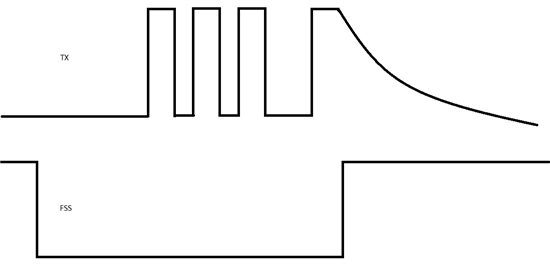
    I've seen the communication with the osciloscope, the FSS and TX and i noticed something good and something strange.

    The communication is happening when CS is low, but after it gets to its HIGH level, the transmission channel have a behaviour like a discharge capacitor, like in the next image:

    I suppose its not normal.

  • Hello Victor,

    This is fine as there is no clock edge when the discharge behavior happens. The diagram shows only CS and TX, but having the clock will reveal that the sampling clock is not toggling anymore.

    Regards

    Amit

  • I used the SLLogicLogger with a Stellaris, and i got this result:

    The second image i dont know if its usefull, but it seem's all alright in the communication.

    CH0 - PA2

    CH1 - PA3

    CH2 - PA4

    CH3 - PA5

    MAster channel, mode 2

  • Hello Victor,

    A logic analyzer will show the transition based on what voltage level has been configured to distinguish between 1 and 0. From SSI Communication perspective it is OK for the discharge and would not affect the protocol.

    Regards

    Amit

  • Good but have you seen the code few post up? Is there any register i have to change that influence the the ports mencioned?

    Why would the slave not execute anything and get so many interrupts?

    This is the pattern:

    PB5, PB6, PB7 and PE4 are outputs, PD0 and PD1 INPUTS.

    Interrupt lights:

    PB5: PD0 and PD1

    Next interrupt, PB6 led: PD0

    Next interrupt, PB7 led: PD1

    Next interrupt, PE4 led: PD0 and PD1

    The interrupts are used in PC6 port

  • Hello Victor,

    Did you check the errata for SSI and the notes in the register section of SSI. there are some issues with SSI Slave interrupts behaving differently. May be it would be helpful to go through that first?

    Also did you think at the suggestion I sent a few posts back to use a Handshake protocol using pre-defined words?

    Regards

    Amit

  • I was just checking that now, the predefined words, because, i looked again at the example code spi_master.c and found that it uses a number to define the MSB.

    Would that influence the way data is transfered?

    The problem is that, the example doesn't use interrupt, its a loopback.

    About the errata, the only thing i found is that the RXTO interrupt may trigger sooner than expected, but im using RXFF.

    Even so, since its clock problems, ill change SysCtlClockGet()/2, to SysCtlClockGet()/4, because there are some problems on the clock prescaler.

  • Hello Victor,

    In the Slave Interrupt Handler the clearing of the interrupt is done as follows

            SSIIntClear(SSI0_BASE, SSI_RXFF | SSI_TXFF);

    for both RXFF and TXFF. it is not a good coding practice to clear interrupts like this. If the condition for TXFF is set then only TXFF must be cleared. Otherwise we may end up with missing interrupts.

    Sometime next week, I would have some time to develop a code for communication between two devices with Interrupt over SSI. I could potentially share the project with you.

    Regards

    Amit

  • Thank's, meanwhile, i'll change that clear interrupt to see if i get any improvement.

  • This is my latest code with communication still failling:

    5432.SSIMasterComplete.rar

    4010.SSISlavecomplete.rar

    i can't find the problem.

  • Hello Victor,

    I ran the two new codes that you sent I and see the following when I start Master and Slave

    Master Log

    Slave Log

    Are you referring to the extra set of Recebi and Enviei that is coming on the Slave side?

    Regards

    Amit

  • Yes, and the fact that, the Master is not receiving from the slave. The Slave on Enviei, should increment a number and send to the Master, but what's happening is that its generating more interrupts than it should and it's not sending anything.

    Also, i still see a delay on the receiving FIFO's from slave to Master