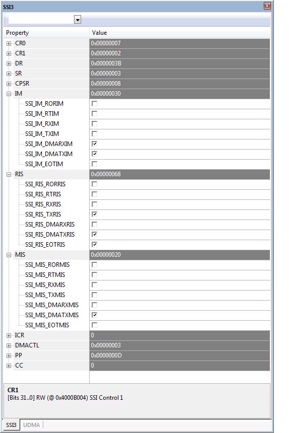
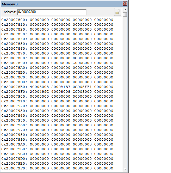
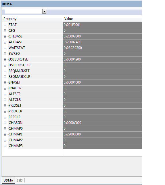
This thread has been locked.

If you have a related question, please click the "Ask a related question" button in the top right corner. The newly created question will be automatically linked to this question.

SSI_DMATX is not generating an interrupt

Hi,

I'm porting the code from Cortex-M3 to TM4C129X evaluation board.

I'm trying to send data to the flash using uDMA.

the uDMA seems to be working (I can see the clock on the scope), but the interrupt is not triggering (does not go to the SSI3_Handler).

I copied a large section of the code from the example file C:\ti\TivaWare_C_Series-2.1.0.12573\utils\spi_flash.c.

It must be something very simple, but I'm not able to find it.

Please help.

I'm attaching sections of the code below.

2677.codeSnapshot.c
void SSI_Init(void)
{
	SSIConfigSetExpClk( SSI3_BASE,
					gSysCtlClock,
					SSI_FRF_MOTO_MODE_0,
					SSI_MODE_MASTER,
					SSI_FLASH_BIT_RATE,
					SSI_FLASH_WORD_SIZE);

	//Enable the SSI
	SSIEnable(SSI3_BASE);

	// disable all interrupt
	SSIIntDisable(SSI3_BASE,SSI_TXEOT |	//transmit fifo is empty
							SSI_DMATX |	//DMA Transmit complete
							SSI_DMARX |	//DMA Receive complete
							SSI_TXFF  |	//TX FIFO half full or less
							SSI_RXFF  |	//RX FIFO half full or more
							SSI_RXTO  |	//rx timeout
							SSI_RXOR);	//rx error
}

void SSIFlash_uDMA_Start(void){

	// Configure the DMA channel
	uDMAChannelAssign(UDMA_CH15_SSI3TX);
	uDMAChannelAttributeDisable(UDMA_CH15_SSI3TX,
								UDMA_ATTR_ALL);

	// Disable the transmit uDMA channel
	uDMAChannelDisable(UDMA_CH15_SSI3TX);

	// Configure the DMA TX channel
	uDMAChannelAttributeEnable(	UDMA_CH15_SSI3TX,
								UDMA_ATTR_USEBURST);
	uDMAChannelControlSet(		UDMA_CH15_SSI3TX,
								UDMA_SIZE_8         |
								UDMA_SRC_INC_8      |
								UDMA_DST_INC_NONE   |
								UDMA_ARB_4);
}
void SSIFlash_uDMA_Write(void, uint32_t u32Address, uint32_t u32Length,	uint8_t *pu8Src){

	// Enable uDMA transmit complete
	SSIIntClear (SSI3_BASE, SSI_DMATX);
	SSIIntEnable(SSI3_BASE, SSI_DMATX);
	SSIDMAEnable(SSI3_BASE, SSI_DMA_TX);

	//start uDMA
	uDMAChannelTransferSet(	UDMA_CH15_SSI3TX,
							UDMA_MODE_BASIC,
							(void *) pu8Src,
							(void *)(u32BaseAddress + SSI_O_DR),
							u32Length);
	uDMAChannelEnable(UDMA_CH15_SSI3TX);
}
void SSIFlash_uDMA_Stop(void){

	//disable uDMA
	SSIDMADisable(SSI3_BASE,SSI_DMA_TX |
							SSI_DMA_RX);
	//disable interrupt
	SSIIntDisable(SSI3_BASE,SSI_TXEOT |	//transmit fifo is empty
							SSI_DMATX |	//DMA Transmit complete
							SSI_DMARX |	//DMA Receive complete
							SSI_TXFF  |	//TX FIFO half full or less
							SSI_RXFF  |	//RX FIFO half full or more
							SSI_RXTO  |	//rx timeout
							SSI_RXOR);	//rx error
}
void SSI3_Handler(void) {

	uint32_t IntStatus;
	uint32_t uDMAModeTx;

	// Read and Clear the interrupt.
	IntStatus = SSIIntStatus(SSI3_BASE, TRUE);
	SSIIntClear(SSI3_BASE, IntStatus);

	//check for Tx done
	if(IntStatus & SSI_DMATX) {
		uDMAModeTx = uDMAChannelModeGet(dmaChannelTx);

		//clear the uDMA Transmit complete bit
		SSIDMADisable(baseAddress, SSI_DMA_TX);
		SSIIntClear(baseAddress, SSI_DMATX);

		if(uDMAModeTx == UDMA_MODE_STOP) {
			//signal to the upper layer that the transmfer has finished
		}
	}
}

thanks.

Khaled.

  • Hello Khaled,

    Have you had a chance to review the Transitioning Designs From Stellaris LM3S Microcontrollers to Tiva C Series MCUs application note?    On page 9 it states:

    On TM4C129x devices, the function of SSI0Tx is on SSI0XDAT0 which is on pin PA4 and the function of SSI0Rx is on SSI0XDAT1 which is on pin PA5.

    Regards,

    Sem Amesawu

  • Sem,

    I aware of the pin swapping and its already been taken into account.

    My problem is not the data on the line ( I can see the clock, and the data0 line toggling fine).

    My problem is the uDMA done interrupt. For some reason, after uDMA has finished transferring the data the SSI_DMATX interrupt does not get set and the SSI3_handler is not called!

    I checked everything at least 4 times already, and can't find the reason for the missing interrupt, and I don't know what to check.

    Khaled.

  • Hello Khaleed,

    I would prefer to see the entire code, rather than just the functions as it is important to understand what is the order f sequence of the functions, that you are using in the code.

    Regards

    Amit

  • Hi Amit,

    Here is the missing link.

    Between this file and the previous file, you should be able to have the full sequence of events.

    2630.codeSnapshot_2.c
    void GPIO_Init(void) {
    
        //--------------------------------------------------------------------
        //Enable the clock to the appropriate GPIO modulel
        //--------------------------------------------------------------------
    	SysCtlPeripheralEnable(SYSCTL_PERIPH_UDMA);
    	SysCtlPeripheralReset(SYSCTL_PERIPH_UDMA);
    
    	SysCtlPeripheralEnable(SYSCTL_PERIPH_SSI3);		//Flash2
    	SysCtlPeripheralReset(SYSCTL_PERIPH_SSI3);
    
    	SysCtlPeripheralEnable(SYSCTL_PERIPH_GPIOC);
    	SysCtlPeripheralReset(SYSCTL_PERIPH_GPIOC);
    
    	SysCtlPeripheralEnable(SYSCTL_PERIPH_GPIOF);
    	SysCtlPeripheralReset(SYSCTL_PERIPH_GPIOF);
    
    	SysCtlPeripheralEnable(SYSCTL_PERIPH_GPIOQ);
    	SysCtlPeripheralReset(SYSCTL_PERIPH_GPIOQ);
    
    
    	//---------------------------------------------------------------
    	//configure JTAG pins
    	//---------------------------------------------------------------
    	GPIOPinConfigure(GPIO_PC0_TCK);	 					//JTAG TCK
    	GPIOPinConfigure(GPIO_PC1_TMS);	 					//JTAG TMS
    	GPIOPinConfigure(GPIO_PC2_TDI);	 					//JTAG TDI
    	GPIOPinConfigure(GPIO_PC3_TDO);	 					//JTAG TDO
    
    	//---------------------------------------------------------------
    	//configure the SSI pins for Flash2(SSI3)
    	//---------------------------------------------------------------
    	GPIOPinConfigure(GPIO_PQ0_SSI3CLK);  				//SSI3 CLK	(Flash 2)
    	GPIOPinConfigure(GPIO_PQ2_SSI3XDAT0);				//SSI3 RX
    	GPIOPinConfigure(GPIO_PF0_SSI3XDAT1);				//SSI3 TX
    
    	//---------------------------------------------------------------
    	//for each function pin, select the type
    	//---------------------------------------------------------------
    	GPIOPinTypeSSI(GPIO_PORTQ_BASE, GPIO_PIN_0 |		//SSI3 Flash2 CLK
    									GPIO_PIN_2);		//SSI3 Flash2 RX
    	GPIOPinTypeSSI(GPIO_PORTF_BASE,	GPIO_PIN_0);		//SSI3 Flash2 TX
    
    	//---------------------------------------------------------------
    	//for each output GPIO pin, select the type
    	//---------------------------------------------------------------
    	GPIOPinTypeGPIOOutput(GPIO_PORTF_BASE, GPIO_PIN_5 |	//SSI3 FLASH2 HOLD
    										   GPIO_PIN_4);	//SSI3 FLASH2 WP
    	GPIOPinTypeGPIOOutput(GPIO_PORTQ_BASE, GPIO_PIN_1);	//SSI3 FLASH2 CS
    }
    
    __task void taskSpiFlash2Tx(void) {
    
    	uint16_t status;
    
    	PACKET_HEADER *packet_p;	//data to transfer to SPI
    	uint32_t readAddress;		//uDMA read address
    	uint32_t writeAddress;		//uDMA write address (SPI buffer)
    	uint32_t transferSize;		//uDMA number of bytes to transfer
    
    
    	//wait for packets to be in the queue head
    	//when a packet is placed in the queue head, send it to the SSI port
    	for( ; ; ) {
    
    		//wait on the Tx event
    		//Note: event flags are not counting objects
    		os_evt_wait_or(TASK_EVENT_TX_FLAG, 0xFFFF);
    
    		//get the next packet to write
    		if(gSpiFlash2.state == SPI_STATE_IDLE) {
    
    			packet_p = queueGet(&gQueueSpiFlash2Tx);
    	        if(packet_p == NULL) continue;
    
    	        gSpiFlash2.state = SPI_STATE_START_TX;
    		}
    
    		//prep the uDMA for the transfer
    		if(gSpiFlash2.state == SPI_STATE_START_TX) {
    			SSIFlash_uDMA_Start();
    
    			GPIOPinWrite(GPIO_PORTQ_BASE, GPIO_PIN_1, 0x00);	//Flash2 CS
    			GPIOPinWrite(GPIO_PORTF_BASE, GPIO_PIN_4, 0xFF);	//Flash2 WRITE PROTECT
    			GPIOPinWrite(GPIO_PORTF_BASE, GPIO_PIN_5, 0xFF);	//Flash2 HOLD
    
    			gSpiFlash2.state = SPI_STATE_TRANS_TX;
    		}
    
    		//transmit data to the SPI flash
    		if(gSpiFlash2.state == SPI_STATE_TRANS_TX) {
    
    			transferSize = packetLength(packet_p);
    			readAddress  = (uint32_t) packetPtr(packet_p, 0);
    			writeAddress = packetAddrEP(packet_p);
    
    			SSIFlash_uDMA_Write(
    						writeAddress,
    						transferSize,
    						(unsigned char *)readAddress);
    
    			gSpiFlash2.state = SPI_STATE_STOP_TX;
    			continue;	//wait for uDMA to finish
    		}
    
    		//stop the transfer to the flash
    		if(gSpiFlash2.state == SPI_STATE_STOP_TX) {
    
    			SSIFlash_uDMA_Stop();
    			packetRemove(packet_p);
    
    			GPIOPinWrite(GPIO_PORTQ_BASE, GPIO_PIN_1, 0xFF);	//Flash2 CS
    			GPIOPinWrite(GPIO_PORTF_BASE, GPIO_PIN_4, 0x00);	//Flash2 WRITE PROTECT
    			GPIOPinWrite(GPIO_PORTF_BASE, GPIO_PIN_5, 0x00);	//Flash2 HOLD
    
    			//always go to Idle state
    			//This way, we will check if there is a pending transfers.
    			gSpiFlash2.state = SPI_STATE_IDLE;
    			os_evt_set(TASK_EVENT_TX_FLAG, gTaskSpiFlash2Tx_ID);
    
    		}
    	}//forever loop
    }
    

    Thanks.

    Khaled.

  • Hello Khaled,

    Thanks. Will get back on this in a couple of days.

    Ragards

    Amit

  • Hello Khaled

    Sorry for the delay on this issue. The code is partial in terms of SSI Baud rate and some other parameters. I am trying to fix those issues, but if you can send the details on the variables in the first code, it would be useful

    Regards

    Amit

  • Amit

    #define SSI_FLASH_BIT_RATE     10000000
    #define SSI_FLASH_WORD_SIZE 8
    gSysCtlClock = SysCtlClockFreqSet(
                            SYSCTL_USE_PLL       |
                            SYSCTL_OSC_MAIN     |
                            SYSCTL_XTAL_25MHZ |
                            SYSCTL_CFG_VCO_480,
                            120000000);        //desired system frequency

    I think those are the messing variables. Please let me know if you need additional information.

    Khaled.

  • Those are missing from the second file

    6036.codeSanpshot_3.c
    #define SPI_STATE_IDLE               0x01    //SPI Idle
    #define SPI_STATE_START_TX           0x02    //SPI write : prime SPI interface
    #define SPI_STATE_TRANS_TX           0x03    //SPI write : transfter samples to SPI
    #define SPI_STATE_STOP_TX            0x04    //SPI write : stop/reset SPI interface
    #define SPI_STATE_START_RX           0x08    //SPI read  : prime SPI interface
    #define SPI_STATE_TRANS_RX           0x09    //SPI read  : transfter to SPI Flash
    #define SPI_STATE_STOP_RX            0x0A    //SPI read  : stop/reset interface
    
    #define TASK_EVENT_TX_FLAG           0x1000  //Tx event
    #define TASK_EVENT_RX_FLAG           0x2000  //Rx event
    #define TASK_EVENT_TX_ERROR_FLAG     0x4000  //Tx error event
    #define TASK_EVENT_RX_ERROR_FLAG     0x8000  //Rx error event
    #define TASK_EVENT_FLAG              0xF000  //any event
    
    
    // global variables
    uint32_t gSysCtlClock;			//the system clock
    OS_TID gTaskSpiFlash2Tx_ID;     //SPI Flash 2 Tx Task ID
    OS_TID gTaskSpiFlash2Rx_ID;     //SPI Flash 2 Rx Task ID
    
    void clockInit() {
    
        // Make sure the main oscillator is enabled because this is required by
        // the PHY.  The system must have a 25MHz crystal attached to the OSC
        // pins.  The SYSCTL_MOSC_HIGHFREQ parameter is used when the crystal
        // frequency is 10MHz or higher.
    	SysCtlMOSCConfigSet(SYSCTL_MOSC_HIGHFREQ);
    
        // Delay while the main oscillator starts up.
    	Delay(5242880);
    
    	//configure the clock
    	gSysCtlClock = SysCtlClockFreqSet( 
    						SYSCTL_USE_PLL    |
    						SYSCTL_OSC_MAIN   |
    						SYSCTL_XTAL_25MHZ |
    						SYSCTL_CFG_VCO_480,
    						120000000);		//desired system frequency
    }
    
    __task void taskInit(void) {
    
    	gTaskSpiFlash2Tx_ID= os_tsk_create(taskSpiFlash2Tx,	TASK_SPI_FLASH_TX_PRIORITY);
    //	gTaskSpiFlash2Rx_ID= os_tsk_create(taskSpiFlash2Rx,	TASK_SPI_FLASH_RX_PRIORITY);
    
    	//remove the task (not needed any more)
    	os_tsk_delete_self();
    }
    
    .

    Khaled.

  • Missed one other command in the initial file. Here is the corrected version

    5488.codeSnapshot.c
    void SSI_Init(void)
    {
    	SSIConfigSetExpClk( SSI3_BASE,
    					gSysCtlClock,
    					SSI_FRF_MOTO_MODE_0,
    					SSI_MODE_MASTER,
    					SSI_FLASH_BIT_RATE,
    					SSI_FLASH_WORD_SIZE);
    
    	//Enable the SSI
    	SSIEnable(SSI3_BASE);
    
    	// disable all interrupt
    	SSIIntDisable(SSI3_BASE,SSI_TXEOT |	//transmit fifo is empty
    							SSI_DMATX |	//DMA Transmit complete
    							SSI_DMARX |	//DMA Receive complete
    							SSI_TXFF  |	//TX FIFO half full or less
    							SSI_RXFF  |	//RX FIFO half full or more
    							SSI_RXTO  |	//rx timeout
    							SSI_RXOR);	//rx error
    }
    
    void SSIFlash_uDMA_Start(void){
    
    	// Configure the DMA channel
    	uDMAChannelAssign(UDMA_CH15_SSI3TX);
    	uDMAChannelAttributeDisable(UDMA_CH15_SSI3TX,
    								UDMA_ATTR_ALL);
    
    	// Disable the transmit uDMA channel
    	uDMAChannelDisable(UDMA_CH15_SSI3TX);
    
    	// Configure the DMA TX channel
    	uDMAChannelAttributeEnable(	UDMA_CH15_SSI3TX,
    								UDMA_ATTR_USEBURST);
    	uDMAChannelControlSet(		UDMA_CH15_SSI3TX,
    								UDMA_SIZE_8         |
    								UDMA_SRC_INC_8      |
    								UDMA_DST_INC_NONE   |
    								UDMA_ARB_4);
    }
    void SSIFlash_uDMA_Write(void, uint32_t u32Address, uint32_t u32Length,	uint8_t *pu8Src){
    
    	// Enable uDMA transmit complete
    	SSIIntClear (SSI3_BASE, SSI_DMATX);
    	SSIIntEnable(SSI3_BASE, SSI_DMATX);
    	SSIDMAEnable(SSI3_BASE, SSI_DMA_TX);
    
    	//start uDMA
    	uDMAChannelTransferSet(	UDMA_CH15_SSI3TX,
    							UDMA_MODE_BASIC,
    							(void *) pu8Src,
    							(void *)(u32BaseAddress + SSI_O_DR),
    							u32Length);
    	uDMAChannelEnable(UDMA_CH15_SSI3TX);
    }
    void SSIFlash_uDMA_Stop(void){
    
    	//disable uDMA
    	SSIDMADisable(SSI3_BASE,SSI_DMA_TX |
    							SSI_DMA_RX);
    	//disable interrupt
    	SSIIntDisable(SSI3_BASE,SSI_TXEOT |	//transmit fifo is empty
    							SSI_DMATX |	//DMA Transmit complete
    							SSI_DMARX |	//DMA Receive complete
    							SSI_TXFF  |	//TX FIFO half full or less
    							SSI_RXFF  |	//RX FIFO half full or more
    							SSI_RXTO  |	//rx timeout
    							SSI_RXOR);	//rx error
    }
    void SSI3_Handler(void) {
    
    	uint32_t IntStatus;
    	uint32_t uDMAModeTx;
    
    	// Read and Clear the interrupt.
    	IntStatus = SSIIntStatus(SSI3_BASE, TRUE);
    	SSIIntClear(SSI3_BASE, IntStatus);
    
    	//check for Tx done
    	if(IntStatus & SSI_DMATX) {
    		uDMAModeTx = uDMAChannelModeGet(dmaChannelTx);
    
    		//clear the uDMA Transmit complete bit
    		SSIDMADisable(baseAddress, SSI_DMA_TX);
    		SSIIntClear(baseAddress, SSI_DMATX);
    
    		if(uDMAModeTx == UDMA_MODE_STOP) {
    			isr_evt_set(TASK_EVENT_TX_FLAG, gTaskSpiFlash2Tx_ID);
    		}
    	}
    }
    

    You should have it all by now. If not, please let me know.

    Khaled.

  • Hello Khaled,

    There were a few initialization missing in the snapshot codes I received. Attached is the low level driver file for SSI with UDMA. I have marked out the added section of code (look for AKA) for changes I had to do.

    1. The uDMA Control Table address was not set

    2. The uDMA Master Enable was not set

    3. The Interrupt enable in the NVIC for SSI3 interrupt was missing.

    4. The way in which SSI DMA request needs to be enabled had to be moved after uDMA Control table initialization.

    After doing the same the SSI3 Interrupt call is working.

    2308.TM4C129_SSI_UDMA.c
    #include <stdint.h>
    #include <stdbool.h>
    #include "inc/hw_memmap.h"
    #include "inc/hw_types.h"
    #include "inc/hw_gpio.h"
    #include "inc/hw_ssi.h"
    #include "inc/hw_sysctl.h"
    #include "inc/hw_udma.h"
    #include "inc/hw_ints.h"
    #include "inc/hw_nvic.h"
    #include "inc/hw_uart.h"
    #include "driverlib/debug.h"
    #include "driverlib/udma.h"
    #include "driverlib/gpio.h"
    #include "driverlib/rom.h"
    #include "driverlib/rom_map.h"
    #include "driverlib/interrupt.h"
    #include "driverlib/pin_map.h"
    #include "driverlib/sysctl.h"
    #include "driverlib/ssi.h"
    #include "driverlib/uart.h"
    #include "utils/uartstdio.h"
    
    //*****************************************************************************
    //
    // Number of bytes to send and receive.
    //
    //*****************************************************************************
    #define NUM_SSI_DATA            3
    volatile uint32_t 	gui32SysClockFreq;
    volatile bool		gbComplete;
    
    //*****************************************************************************
    //
    // The control table used by the uDMA controller.  This table must be aligned
    // to a 1024 byte boundary.
    //
    //*****************************************************************************
    #if defined(ewarm)
    #pragma data_alignment=1024
    uint8_t pui8ControlTable[1024];
    #elif defined(ccs)
    #pragma DATA_ALIGN(pui8ControlTable, 1024)
    uint8_t pui8ControlTable[1024];
    #else
    uint8_t pui8ControlTable[1024] __attribute__ ((aligned(1024)));
    #endif
    
    //*****************************************************************************
    //
    // This function sets up UART0 to be used for a console to display information
    // as the example is running.
    //
    //*****************************************************************************
    void
    InitConsole(void)
    {
        //
        // Enable GPIO port A which is used for UART0 pins.
        // TODO: change this to whichever GPIO port you are using.
        //
        SysCtlPeripheralEnable(SYSCTL_PERIPH_GPIOA);
    
        //
        // Configure the pin muxing for UART0 functions on port A0 and A1.
        // This step is not necessary if your part does not support pin muxing.
        // TODO: change this to select the port/pin you are using.
        //
        GPIOPinConfigure(GPIO_PA0_U0RX);
        GPIOPinConfigure(GPIO_PA1_U0TX);
    
        //
        // Enable UART0 so that we can configure the clock.
        //
        SysCtlPeripheralEnable(SYSCTL_PERIPH_UART0);
    
        //
        // Use the internal 16MHz oscillator as the UART clock source.
        //
        UARTClockSourceSet(UART0_BASE, UART_CLOCK_PIOSC);
    
        //
        // Select the alternate (UART) function for these pins.
        // TODO: change this to select the port/pin you are using.
        //
        GPIOPinTypeUART(GPIO_PORTA_BASE, GPIO_PIN_0 | GPIO_PIN_1);
    
        //
        // Initialize the UART for console I/O.
        //
        UARTStdioConfig(0, 115200, 16000000);
    }
    
    //
    // AKA: Added the new function for uDMA Initialization
    //
    void UDMA_Init(void)
    {
        //
        // Enable the uDMA controller.
        //
        uDMAEnable();
    
        //
        // Point at the control table to use for channel control structures.
        //
        uDMAControlBaseSet(pui8ControlTable);
    
    }
    
    void SSI_Init(void)
    {
    	SSIConfigSetExpClk( SSI3_BASE,
    						gui32SysClockFreq,
    						SSI_FRF_MOTO_MODE_0,
    						SSI_MODE_MASTER,
    						10000000,
    						8);
    
    	//Enable the SSI
    	SSIEnable(SSI3_BASE);
    
    	// disable all interrupt
    	SSIIntDisable(SSI3_BASE,SSI_TXEOT |	//transmit fifo is empty
    							SSI_DMATX |	//DMA Transmit complete
    							SSI_DMARX |	//DMA Receive complete
    							SSI_TXFF  |	//TX FIFO half full or less
    							SSI_RXFF  |	//RX FIFO half full or more
    							SSI_RXTO  |	//rx timeout
    							SSI_RXOR);	//rx error
    
    	// AKA : Enable the Interrupt from the SSI-3 to be registered by NVIC
    	IntEnable(INT_SSI3);
    }
    
    void SSIFlash_uDMA_Start(void){
    
    	// Configure the DMA channel
    	uDMAChannelAssign(UDMA_CH15_SSI3TX);
    	uDMAChannelAttributeDisable(UDMA_CH15_SSI3TX,
    								UDMA_ATTR_ALL);
    
    	// Disable the transmit uDMA channel
    	uDMAChannelDisable(UDMA_CH15_SSI3TX);
    
    	// Configure the DMA TX channel
    	uDMAChannelAttributeEnable(	UDMA_CH15_SSI3TX,
    								UDMA_ATTR_USEBURST);
    	uDMAChannelControlSet(		UDMA_CH15_SSI3TX,
    								UDMA_SIZE_8         |
    								UDMA_SRC_INC_8      |
    								UDMA_DST_INC_NONE   |
    								UDMA_ARB_4);
    }
    
    void SSIFlash_uDMA_Write(uint32_t u32Address, uint32_t u32Length,	uint8_t *pu8Src)
    {
    
    	// Enable uDMA transmit complete
    	SSIIntClear (SSI3_BASE, SSI_DMATX);
    	SSIIntEnable(SSI3_BASE, SSI_DMATX);
    
    	//start uDMA
    	uDMAChannelTransferSet(	UDMA_CH15_SSI3TX,
    							UDMA_MODE_BASIC,
    							(void *) pu8Src,
    							(void *)(SSI3_BASE + SSI_O_DR),
    							u32Length);
    	uDMAChannelEnable(UDMA_CH15_SSI3TX);
    	// AKA
    	SSIDMAEnable(SSI3_BASE, SSI_DMA_TX);
    }
    
    void SSIFlash_uDMA_Stop(void){
    
    	//disable uDMA
    	SSIDMADisable(SSI3_BASE,SSI_DMA_TX |
    							SSI_DMA_RX);
    	//disable interrupt
    	SSIIntDisable(SSI3_BASE,SSI_TXEOT |	//transmit fifo is empty
    							SSI_DMATX |	//DMA Transmit complete
    							SSI_DMARX |	//DMA Receive complete
    							SSI_TXFF  |	//TX FIFO half full or less
    							SSI_RXFF  |	//RX FIFO half full or more
    							SSI_RXTO  |	//rx timeout
    							SSI_RXOR);	//rx error
    }
    
    void GPIO_Init(void) {
    
        //--------------------------------------------------------------------
        //Enable the clock to the appropriate GPIO modulel
        //--------------------------------------------------------------------
    	SysCtlPeripheralEnable(SYSCTL_PERIPH_UDMA);
    	SysCtlPeripheralReset(SYSCTL_PERIPH_UDMA);
    
    	SysCtlPeripheralEnable(SYSCTL_PERIPH_SSI3);		//Flash2
    	SysCtlPeripheralReset(SYSCTL_PERIPH_SSI3);
    
    	SysCtlPeripheralEnable(SYSCTL_PERIPH_GPIOC);
    	SysCtlPeripheralReset(SYSCTL_PERIPH_GPIOC);
    
    	SysCtlPeripheralEnable(SYSCTL_PERIPH_GPIOF);
    	SysCtlPeripheralReset(SYSCTL_PERIPH_GPIOF);
    
    	SysCtlPeripheralEnable(SYSCTL_PERIPH_GPIOQ);
    	SysCtlPeripheralReset(SYSCTL_PERIPH_GPIOQ);
    
    
    	//---------------------------------------------------------------
    	//configure JTAG pins
    	//---------------------------------------------------------------
    	GPIOPinConfigure(GPIO_PC0_TCK);	 					//JTAG TCK
    	GPIOPinConfigure(GPIO_PC1_TMS);	 					//JTAG TMS
    	GPIOPinConfigure(GPIO_PC2_TDI);	 					//JTAG TDI
    	GPIOPinConfigure(GPIO_PC3_TDO);	 					//JTAG TDO
    
    	//---------------------------------------------------------------
    	//configure the SSI pins for Flash2(SSI3)
    	//---------------------------------------------------------------
    	GPIOPinConfigure(GPIO_PQ0_SSI3CLK);  				//SSI3 CLK	(Flash 2)
    	GPIOPinConfigure(GPIO_PQ2_SSI3XDAT0);				//SSI3 RX
    	GPIOPinConfigure(GPIO_PF0_SSI3XDAT1);				//SSI3 TX
    
    	//---------------------------------------------------------------
    	//for each function pin, select the type
    	//---------------------------------------------------------------
    	GPIOPinTypeSSI(GPIO_PORTQ_BASE, GPIO_PIN_0 |		//SSI3 Flash2 CLK
    									GPIO_PIN_2);		//SSI3 Flash2 RX
    	GPIOPinTypeSSI(GPIO_PORTF_BASE,	GPIO_PIN_0);		//SSI3 Flash2 TX
    
    	//---------------------------------------------------------------
    	//for each output GPIO pin, select the type
    	//---------------------------------------------------------------
    	GPIOPinTypeGPIOOutput(GPIO_PORTF_BASE, GPIO_PIN_5 |	//SSI3 FLASH2 HOLD
    										   GPIO_PIN_4);	//SSI3 FLASH2 WP
    	GPIOPinTypeGPIOOutput(GPIO_PORTQ_BASE, GPIO_PIN_1);	//SSI3 FLASH2 CS
    }
    
    void SSI3_Handler(void) {
    
    	uint32_t IntStatus;
    	uint32_t uDMAModeTx;
    
    	// Read and Clear the interrupt.
    	IntStatus = SSIIntStatus(SSI3_BASE, true);
    	SSIIntClear(SSI3_BASE, IntStatus);
    
    	//check for Tx done
    	if(IntStatus & SSI_DMATX) {
    		uDMAModeTx = uDMAChannelModeGet(UDMA_CH15_SSI3TX);
    
    		//clear the uDMA Transmit complete bit
    		SSIDMADisable(SSI3_BASE, SSI_DMA_TX);
    		SSIIntClear(SSI3_BASE, SSI_DMATX);
    
    		if(uDMAModeTx == UDMA_MODE_STOP) {
    			//signal to the upper layer that the transmfer has finished
    			gbComplete = true;
    		}
    	}
    }
    
    //*****************************************************************************
    //
    // Configure SSI3 in master Freescale (SPI) mode.  This example will send out
    // 3 bytes of data, then wait for 3 bytes of data to come in.  This will all be
    // done using the polling method.
    //
    //*****************************************************************************
    int
    main(void)
    {
    	uint8_t ui8TxBuffer[16];
    
        //
        // Set the clocking to run directly from the external crystal/oscillator.
        // TODO: The SYSCTL_XTAL_ value must be changed to match the value of the
        // crystal on your board.
        //
        gui32SysClockFreq = SysCtlClockFreqSet((SYSCTL_XTAL_25MHZ |
                                                SYSCTL_OSC_MAIN |
                                                SYSCTL_USE_PLL |
                                                SYSCTL_CFG_VCO_480), 120000000);
        //
        // Set up the serial console to use for displaying messages.  This is
        // just for this example program and is not needed for SSI operation.
        //
        InitConsole();
    
        //
        // Display the setup on the console.
        //
        UARTprintf("SSI ->\n");
        UARTprintf("  Mode: SPI\n");
        UARTprintf("  Data: 8-bit\n\n");
    
        //
        // Initialize GPIO, SSI and UDMA Clocks
        //
        GPIO_Init();
        SSI_Init();
        UDMA_Init();
        SSIFlash_uDMA_Start();
    
        gbComplete = false;
        SSIFlash_uDMA_Write(0x0,16,&ui8TxBuffer);
    	while(!gbComplete);
    	SSIFlash_uDMA_Stop();
    
        //
        // Loop Here
        //
        while(1);
    }
    

    Regards

    Amit

  • Amit,

    Thanks, I'm getting the uDMA interrupt now. I was missing the The Interrupt enable in the NVIC for SSI3 interrupt ;-)

    However after the first uDMA interrupt, i.e. the second uDMA interrupt, the

                                    uDMAChannelModeGet(UDMA_CH15_SSI3TX) !=  UDMA_MODE_STOP;    !!!!!

    I'm not able to understand why the SSI3_Handler( ) got called if the transfer is not done yet !!!!

    I remembered that there was a issue on how to clear the interrupt flag. I tried to play with that (see code in red below) but the problem got even worse. Now the SSI3_Handler( ) keep on getting triggered back to back indefinitely !!!!

    void SSI3_Handler(void) {
        uint32_t IntStatus;
        uint32_t uDMAModeTx;

        // Read and Clear the interrupt.
        IntStatus = SSIIntStatus(SSI3_BASE, true);
        SSIIntClear(SSI3_BASE, IntStatus);

        //check for Tx done
        if(IntStatus & SSI_DMATX) {
            uDMAModeTx = uDMAChannelModeGet(UDMA_CH15_SSI3TX);  //NOT equal to UDMA_MODE_STOP

            //clear the uDMA Transmit complete bit
            SSIDMADisable(SSI3_BASE, SSI_DMA_TX);
            SSIIntClear(SSI3_BASE, SSI_DMATX);  //DOES NOT clear the interrupt flag
            SSIDMAEnable(SSI3_BASE, SSI_DMA_TX);
     
            if(uDMAModeTx == UDMA_MODE_STOP) {
                //signal to the upper layer that the transfer has finished
                gbComplete = true;
            }
        }
    }

  • Hello Khaled,

    Good that the first issue is now resolved. The issue that you mentioned is a know issue on the TM4C for which an errata is being worked on.

    The way to get around is that only do the SSIDMAEnable after the uDMA has been reconfigured. Basically the user/application code must only use the SSIDMADisable and SSIDMAEnable to manage the uDMA's interaction with the SSI.

    Regards

    Amit

  • Amit,

    I'm not sure that I fully understood where to use the SSIDMAEnable( ) and SSIDMADisable( ).

    Initally I thought to enable uDMA once in the initialization function and leave it enabled all the time. However when I started reading more about procedure needed to clear the uDMA Tx done flag "SSI_DMATX", I was under the impression that the only way to do it, is if we encapsulate the SSIIntClear( ) between SSIDMADisable( ) and SSIDMAEnable( ).

    Have I mi-understood that section?

    Can you modify the code that you have sent to me and put those 2 commands in proper place?

    In addition, I would like to understand why the SSI_handler triggerd if the uDMA was not done yet!!!!

    From my observation, the SSI_handler was triggered, but the uDMAChannelModeGet(UDMA_CH15_SSI3TX) != UDMA_MODE_STOP;    !!!!!

    thanks

    Khaled.

  • Hello Khaled,

    It is a confirmed issue on the interaction model between uDMA and SSI. When the SSIDMAEnable is called after clearing the interrupt, it immediately sends a DMA Request to the uDMA. Since the uDMA has the STOP set it will put back DONE causing the TXDMADONE interrupt to refire. Thus to avoid the interrupt firing w/o any transfer the SSIDMAEnable must be set only when the next transfer has to be scheduled.

    Attached is the code modified to do the same repeatedly.

    3404.TM4C129_SSI_UDMA.zip

    Regards

    Amit

  • its working now :-)

    thanks.

    Khaled.

  • Hello Khaled,

    That is good news indeed. Is the issue on boot loader still open?

    Regards

    Amit

  • Yes it is.

    a couple of days ago, I sent subsection of the code to one of your colleague "Sai".

    I thought that you have asked him to take over!

    Khaled.

  • Hi Amit,
    It has been a while but I got busy with another project.
    Now that I'm back on this one, I implemented the modification that you have suggested and I did recieve the SSI3_Handler( ) SSI_DMATX interrupt :-)

    But I'm getting tooooo many of them. As expected, the first interrupt is received after I start the uDMA, I clear interrupt it in the SSI3_Handler( ), do my data processing, and as soon as I exit the SSI3_Handler( ), I get the SAME SSI_DMATX interrupt again.
    this loops goes on forever.


    Khaled.
  • Hello Khaled,

    Did you disable the DMA channel and re-enable only when the next data transfer has to be started after reconfiguring the DMA channel?

    Regards
    Amit
  • Yes, that was my mistake:re-enabling it after the data transfer has been started fixed the issue. :-)
    thanks.
    Khaled.
  • Hi Amit,

    Now I have similar problem on the Rx uDMA read: SSI3_Handler( ) doesn't trigger when Rx uDMA is done.

    The Tx uDMA however does trigger.

    From what I can tell, Rx uDMA didn't even start since the content of the ui8RxBuffer is still 0;

    I modeled it in the same way as the Tx uDMA read code with the only exception, that for every read I have to perform a corresponding dummy write.

    I have attached the modified code (same project as the one that you have sent to me before).

    Could you please take another look?

    thanks.

    Khaled.

    TM4C129_SSI_UDMA.c
    #include <stdint.h>
    #include <stdbool.h>
    #include "inc/hw_memmap.h"
    #include "inc/hw_types.h"
    #include "inc/hw_gpio.h"
    #include "inc/hw_ssi.h"
    #include "inc/hw_sysctl.h"
    #include "inc/hw_udma.h"
    #include "inc/hw_ints.h"
    #include "inc/hw_nvic.h"
    #include "inc/hw_uart.h"
    #include "driverlib/debug.h"
    #include "driverlib/udma.h"
    #include "driverlib/gpio.h"
    #include "driverlib/rom.h"
    #include "driverlib/rom_map.h"
    #include "driverlib/interrupt.h"
    #include "driverlib/pin_map.h"
    #include "driverlib/sysctl.h"
    #include "driverlib/ssi.h"
    #include "driverlib/uart.h"
    #include "utils/uartstdio.h"
    
    //*****************************************************************************
    //
    // Number of bytes to send and receive.
    //
    //*****************************************************************************
    #define NUM_SSI_DATA            3
    volatile uint32_t 	gui32SysClockFreq;
    volatile bool		gbComplete;
    
    //*****************************************************************************
    //
    // The control table used by the uDMA controller.  This table must be aligned
    // to a 1024 byte boundary.
    //
    //*****************************************************************************
    #if defined(ewarm)
    #pragma data_alignment=1024
    uint8_t pui8ControlTable[1024];
    #elif defined(ccs)
    #pragma DATA_ALIGN(pui8ControlTable, 1024)
    uint8_t pui8ControlTable[1024];
    #else
    uint8_t pui8ControlTable[1024] __attribute__ ((aligned(1024)));
    #endif
    
    //*****************************************************************************
    //
    // This function sets up UART0 to be used for a console to display information
    // as the example is running.
    //
    //*****************************************************************************
    void
    InitConsole(void)
    {
        //
        // Enable GPIO port A which is used for UART0 pins.
        // TODO: change this to whichever GPIO port you are using.
        //
        SysCtlPeripheralEnable(SYSCTL_PERIPH_GPIOA);
    
        //
        // Configure the pin muxing for UART0 functions on port A0 and A1.
        // This step is not necessary if your part does not support pin muxing.
        // TODO: change this to select the port/pin you are using.
        //
        GPIOPinConfigure(GPIO_PA0_U0RX);
        GPIOPinConfigure(GPIO_PA1_U0TX);
    
        //
        // Enable UART0 so that we can configure the clock.
        //
        SysCtlPeripheralEnable(SYSCTL_PERIPH_UART0);
    
        //
        // Use the internal 16MHz oscillator as the UART clock source.
        //
        UARTClockSourceSet(UART0_BASE, UART_CLOCK_PIOSC);
    
        //
        // Select the alternate (UART) function for these pins.
        // TODO: change this to select the port/pin you are using.
        //
        GPIOPinTypeUART(GPIO_PORTA_BASE, GPIO_PIN_0 | GPIO_PIN_1);
    
        //
        // Initialize the UART for console I/O.
        //
        UARTStdioConfig(0, 115200, 16000000);
    }
    
    //
    // AKA: Added the new function for uDMA Initialization
    //
    void UDMA_Init(void)
    {
        //
        // Enable the uDMA controller.
        //
        uDMAEnable();
    
        //
        // Point at the control table to use for channel control structures.
        //
        uDMAControlBaseSet(pui8ControlTable);
    
    }
    
    void SSI_Init(void)
    {
    	SSIConfigSetExpClk( SSI3_BASE,
    						gui32SysClockFreq,
    						SSI_FRF_MOTO_MODE_0,
    						SSI_MODE_MASTER,
    						10000000,
    						8);
    
    	//Enable the SSI
    	SSIEnable(SSI3_BASE);
    
    	// disable all interrupt
    	SSIIntDisable(SSI3_BASE,SSI_TXEOT |	//transmit fifo is empty
    							SSI_DMATX |	//DMA Transmit complete
    							SSI_DMARX |	//DMA Receive complete
    							SSI_TXFF  |	//TX FIFO half full or less
    							SSI_RXFF  |	//RX FIFO half full or more
    							SSI_RXTO  |	//rx timeout
    							SSI_RXOR);	//rx error
    
    	// AKA : Enable the Interrupt from the SSI-3 to be registered by NVIC
    	IntEnable(INT_SSI3);
    }
    
    void SSIFlash_uDMA_Start(void){
    
    	// Configure the DMA channel
    	uDMAChannelAssign(UDMA_CH15_SSI3TX);
    	uDMAChannelAttributeDisable(UDMA_CH15_SSI3TX,
    								UDMA_ATTR_ALL);
    
    	// Disable the transmit uDMA channel
    	uDMAChannelDisable(UDMA_CH15_SSI3TX);
    
    	// Configure the DMA TX channel
    	uDMAChannelAttributeEnable(	UDMA_CH15_SSI3TX,
    								UDMA_ATTR_USEBURST);
    	uDMAChannelControlSet(		UDMA_CH15_SSI3TX,
    								UDMA_SIZE_8         |
    								UDMA_SRC_INC_8      |
    								UDMA_DST_INC_NONE   |
    								UDMA_ARB_4);
    }
    
    void SSIFlash_uDMA_Write(uint32_t u32Address, uint32_t u32Length,	uint8_t *pu8Src)
    {
    
    	// Enable uDMA transmit complete
    	SSIIntClear (SSI3_BASE, SSI_DMATX);
    	SSIIntEnable(SSI3_BASE, SSI_DMATX);
    
    	//start uDMA
    	uDMAChannelTransferSet(	UDMA_CH15_SSI3TX,
    							UDMA_MODE_BASIC,
    							(void *) pu8Src,
    							(void *)(SSI3_BASE + SSI_O_DR),
    							u32Length);
    	uDMAChannelEnable(UDMA_CH15_SSI3TX);
    	// AKA
    	SSIDMAEnable(SSI3_BASE, SSI_DMA_TX);
    }
    
    void SSIFlash_uDMA_Stop(void){
    
    	//disable uDMA
    	SSIDMADisable(SSI3_BASE,SSI_DMA_TX |
    							SSI_DMA_RX);
    	//disable interrupt
    	SSIIntDisable(SSI3_BASE,SSI_TXEOT |	//transmit fifo is empty
    							SSI_DMATX |	//DMA Transmit complete
    							SSI_DMARX |	//DMA Receive complete
    							SSI_TXFF  |	//TX FIFO half full or less
    							SSI_RXFF  |	//RX FIFO half full or more
    							SSI_RXTO  |	//rx timeout
    							SSI_RXOR);	//rx error
    }
    
    void GPIO_Init(void) {
    
        //--------------------------------------------------------------------
        //Enable the clock to the appropriate GPIO modulel
        //--------------------------------------------------------------------
    	SysCtlPeripheralEnable(SYSCTL_PERIPH_UDMA);
    	SysCtlPeripheralReset(SYSCTL_PERIPH_UDMA);
    
    	SysCtlPeripheralEnable(SYSCTL_PERIPH_SSI3);		//Flash2
    	SysCtlPeripheralReset(SYSCTL_PERIPH_SSI3);
    
    	SysCtlPeripheralEnable(SYSCTL_PERIPH_GPIOC);
    	SysCtlPeripheralReset(SYSCTL_PERIPH_GPIOC);
    
    	SysCtlPeripheralEnable(SYSCTL_PERIPH_GPIOF);
    	SysCtlPeripheralReset(SYSCTL_PERIPH_GPIOF);
    
    	SysCtlPeripheralEnable(SYSCTL_PERIPH_GPIOQ);
    	SysCtlPeripheralReset(SYSCTL_PERIPH_GPIOQ);
    
    
    	//---------------------------------------------------------------
    	//configure JTAG pins
    	//---------------------------------------------------------------
    	GPIOPinConfigure(GPIO_PC0_TCK);	 					//JTAG TCK
    	GPIOPinConfigure(GPIO_PC1_TMS);	 					//JTAG TMS
    	GPIOPinConfigure(GPIO_PC2_TDI);	 					//JTAG TDI
    	GPIOPinConfigure(GPIO_PC3_TDO);	 					//JTAG TDO
    
    	//---------------------------------------------------------------
    	//configure the SSI pins for Flash2(SSI3)
    	//---------------------------------------------------------------
    	GPIOPinConfigure(GPIO_PQ0_SSI3CLK);  				//SSI3 CLK	(Flash 2)
    	GPIOPinConfigure(GPIO_PQ2_SSI3XDAT0);				//SSI3 RX
    	GPIOPinConfigure(GPIO_PF0_SSI3XDAT1);				//SSI3 TX
    
    	//---------------------------------------------------------------
    	//for each function pin, select the type
    	//---------------------------------------------------------------
    	GPIOPinTypeSSI(GPIO_PORTQ_BASE, GPIO_PIN_0 |		//SSI3 Flash2 CLK
    									GPIO_PIN_2);		//SSI3 Flash2 RX
    	GPIOPinTypeSSI(GPIO_PORTF_BASE,	GPIO_PIN_0);		//SSI3 Flash2 TX
    
    	//---------------------------------------------------------------
    	//for each output GPIO pin, select the type
    	//---------------------------------------------------------------
    	GPIOPinTypeGPIOOutput(GPIO_PORTF_BASE, GPIO_PIN_5 |	//SSI3 FLASH2 HOLD
    										   GPIO_PIN_4);	//SSI3 FLASH2 WP
    	GPIOPinTypeGPIOOutput(GPIO_PORTQ_BASE, GPIO_PIN_1);	//SSI3 FLASH2 CS
    }
    
    void SSI3_Handler(void) {
    
    	uint32_t IntStatus;
    	uint32_t uDMAModeTx;
    
    	// Read and Clear the interrupt.
    	IntStatus = SSIIntStatus(SSI3_BASE, true);
    	SSIIntClear(SSI3_BASE, IntStatus);
    
    	//check for Tx done
    	if(IntStatus & SSI_DMATX) {
    		uDMAModeTx = uDMAChannelModeGet(UDMA_CH15_SSI3TX);
    
    		//clear the uDMA Transmit complete bit
    		SSIDMADisable(SSI3_BASE, SSI_DMA_TX);
    		SSIIntClear(SSI3_BASE, SSI_DMATX);
    
    		if(uDMAModeTx == UDMA_MODE_STOP) {
    			//signal to the upper layer that the transmfer has finished
    			gbComplete = true;
    		}
    	}
    }
    
    //*****************************************************************************
    //
    // Configure SSI3 in master Freescale (SPI) mode.  This example will send out
    // 3 bytes of data, then wait for 3 bytes of data to come in.  This will all be
    // done using the polling method.
    //
    //*****************************************************************************
    int
    main(void)
    {
    	uint8_t ui8TxBuffer[16];
    
        //
        // Set the clocking to run directly from the external crystal/oscillator.
        // TODO: The SYSCTL_XTAL_ value must be changed to match the value of the
        // crystal on your board.
        //
        gui32SysClockFreq = SysCtlClockFreqSet((SYSCTL_XTAL_25MHZ |
                                                SYSCTL_OSC_MAIN |
                                                SYSCTL_USE_PLL |
                                                SYSCTL_CFG_VCO_480), 120000000);
        //
        // Set up the serial console to use for displaying messages.  This is
        // just for this example program and is not needed for SSI operation.
        //
        InitConsole();
    
        //
        // Display the setup on the console.
        //
        UARTprintf("SSI ->\n");
        UARTprintf("  Mode: SPI\n");
        UARTprintf("  Data: 8-bit\n\n");
    
        //
        // Initialize GPIO, SSI and UDMA Clocks
        //
        GPIO_Init();
        SSI_Init();
        UDMA_Init();
        SSIFlash_uDMA_Start();
    
        while(1)
        {
            gbComplete = false;
            SSIFlash_uDMA_Write(0x0,16,&ui8TxBuffer);
        	while(!gbComplete);
        	SSIFlash_uDMA_Stop();
        }
    
        //
        // Loop Here
        //
        while(1);
    }
    

  • Hi Amit

    Sorry I sent you the old file. Here is the new one.

    Khaled.

    TM4C129_SSI_UDMA_RX.c
    #include <stdint.h>
    #include <stdbool.h>
    #include "inc/hw_memmap.h"
    #include "inc/hw_types.h"
    #include "inc/hw_gpio.h"
    #include "inc/hw_ssi.h"
    #include "inc/hw_sysctl.h"
    #include "inc/hw_udma.h"
    #include "inc/hw_ints.h"
    #include "inc/hw_nvic.h"
    #include "inc/hw_uart.h"
    #include "driverlib/debug.h"
    #include "driverlib/udma.h"
    #include "driverlib/gpio.h"
    #include "driverlib/rom.h"
    #include "driverlib/rom_map.h"
    #include "driverlib/interrupt.h"
    #include "driverlib/pin_map.h"
    #include "driverlib/sysctl.h"
    #include "driverlib/ssi.h"
    #include "driverlib/uart.h"
    #include "utils/uartstdio.h"
    
    //*****************************************************************************
    //
    // Number of bytes to send and receive.
    //
    //*****************************************************************************
    #define NUM_SSI_DATA            3
    volatile uint32_t 	gui32SysClockFreq;
    volatile bool		gbComplete;
    
    //*****************************************************************************
    //
    // The control table used by the uDMA controller.  This table must be aligned
    // to a 1024 byte boundary.
    //
    //*****************************************************************************
    #if defined(ewarm)
    #pragma data_alignment=1024
    uint8_t pui8ControlTable[1024];
    #elif defined(ccs)
    #pragma DATA_ALIGN(pui8ControlTable, 1024)
    uint8_t pui8ControlTable[1024];
    #else
    uint8_t pui8ControlTable[1024] __attribute__ ((aligned(1024)));
    #endif
    
    //*****************************************************************************
    //
    // This function sets up UART0 to be used for a console to display information
    // as the example is running.
    //
    //*****************************************************************************
    void
    InitConsole(void)
    {
        //
        // Enable GPIO port A which is used for UART0 pins.
        // TODO: change this to whichever GPIO port you are using.
        //
        SysCtlPeripheralEnable(SYSCTL_PERIPH_GPIOA);
    
        //
        // Configure the pin muxing for UART0 functions on port A0 and A1.
        // This step is not necessary if your part does not support pin muxing.
        // TODO: change this to select the port/pin you are using.
        //
        GPIOPinConfigure(GPIO_PA0_U0RX);
        GPIOPinConfigure(GPIO_PA1_U0TX);
    
        //
        // Enable UART0 so that we can configure the clock.
        //
        SysCtlPeripheralEnable(SYSCTL_PERIPH_UART0);
    
        //
        // Use the internal 16MHz oscillator as the UART clock source.
        //
        UARTClockSourceSet(UART0_BASE, UART_CLOCK_PIOSC);
    
        //
        // Select the alternate (UART) function for these pins.
        // TODO: change this to select the port/pin you are using.
        //
        GPIOPinTypeUART(GPIO_PORTA_BASE, GPIO_PIN_0 | GPIO_PIN_1);
    
        //
        // Initialize the UART for console I/O.
        //
        UARTStdioConfig(0, 115200, 16000000);
    }
    
    //
    // AKA: Added the new function for uDMA Initialization
    //
    void UDMA_Init(void)
    {
        //
        // Enable the uDMA controller.
        //
        uDMAEnable();
    
        //
        // Point at the control table to use for channel control structures.
        //
        uDMAControlBaseSet(pui8ControlTable);
    
    }
    
    void SSI_Init(void)
    {
    	SSIConfigSetExpClk( SSI3_BASE,
    						gui32SysClockFreq,
    						SSI_FRF_MOTO_MODE_0,
    						SSI_MODE_MASTER,
    						10000000,
    						8);
    
    	//Enable the SSI
    	SSIEnable(SSI3_BASE);
    
    	// disable all interrupt
    	SSIIntDisable(SSI3_BASE,SSI_TXEOT |	//transmit fifo is empty
    							SSI_DMATX |	//DMA Transmit complete
    							SSI_DMARX |	//DMA Receive complete
    							SSI_TXFF  |	//TX FIFO half full or less
    							SSI_RXFF  |	//RX FIFO half full or more
    							SSI_RXTO  |	//rx timeout
    							SSI_RXOR);	//rx error
    
    	// AKA : Enable the Interrupt from the SSI-3 to be registered by NVIC
    	IntEnable(INT_SSI3);
    }
    
    void SSIFlash_uDMA_Start(void){
    
    	// Configure the DMA channel
    	uDMAChannelAssign(UDMA_CH14_SSI3RX);
    	uDMAChannelAssign(UDMA_CH15_SSI3TX);
    	uDMAChannelAttributeDisable(UDMA_CH14_SSI3RX,
    								UDMA_ATTR_ALL);
    	uDMAChannelAttributeDisable(UDMA_CH15_SSI3TX,
    								UDMA_ATTR_ALL);
    
    	// Disable the transmit uDMA channel
    	uDMAChannelDisable(UDMA_CH14_SSI3RX);
    	uDMAChannelDisable(UDMA_CH15_SSI3TX);
    
    	// Configure the DMA TX channel
    	uDMAChannelAttributeEnable(	UDMA_CH14_SSI3RX,
    								UDMA_ATTR_USEBURST);
    	uDMAChannelControlSet(		UDMA_CH14_SSI3RX,
    								UDMA_SIZE_8         |
    								UDMA_SRC_INC_NONE   |
    								UDMA_DST_INC_8      |
    								UDMA_ARB_4);
    
    	uDMAChannelAttributeEnable(	UDMA_CH15_SSI3TX,
    								UDMA_ATTR_USEBURST);
    	uDMAChannelControlSet(		UDMA_CH15_SSI3TX,
    								UDMA_SIZE_8         |
    								UDMA_SRC_INC_NONE   |
    								UDMA_DST_INC_NONE   |
    								UDMA_ARB_4);
    }
    
    void SSIFlash_uDMA_Read(uint32_t u32Address, uint32_t u32Length, uint8_t *pu8Dst)
    {
    	uint8_t u8Tmp = 0;
    
    	// Enable uDMA transmit complete
    	SSIIntClear (SSI3_BASE, SSI_DMATX | SSI_DMARX);
    	SSIIntEnable(SSI3_BASE, SSI_DMATX | SSI_DMARX);
    
    	//start uDMA
    	uDMAChannelTransferSet(	UDMA_CH14_SSI3RX,
    							UDMA_MODE_BASIC,
    							(void *)(SSI0_BASE + SSI_O_DR),
    							(void *)pu8Dst,
    							u32Length);
    	uDMAChannelTransferSet(	UDMA_CH15_SSI3TX,
    							UDMA_MODE_BASIC,
    							(void *) &u8Tmp,
    							(void *)(SSI0_BASE + SSI_O_DR),
    							u32Length);
    	uDMAChannelEnable(UDMA_CH15_SSI3TX | UDMA_CH14_SSI3RX);
    	// AKA
    	SSIDMAEnable(SSI3_BASE, SSI_DMA_TX | SSI_DMA_RX);
    }
    void SSIFlash_uDMA_Write(uint32_t u32Address, uint32_t u32Length, uint8_t *pu8Src)
    {
    
    	// Enable uDMA transmit complete
    	SSIIntClear (SSI3_BASE, SSI_DMATX);
    	SSIIntEnable(SSI3_BASE, SSI_DMATX);
    
    	//start uDMA
    	uDMAChannelTransferSet(	UDMA_CH15_SSI3TX,
    							UDMA_MODE_BASIC,
    							(void *) pu8Src,
    							(void *)(SSI3_BASE + SSI_O_DR),
    							u32Length);
    	uDMAChannelEnable(UDMA_CH15_SSI3TX);
    	// AKA
    	SSIDMAEnable(SSI3_BASE, SSI_DMA_TX);
    }
    
    void SSIFlash_uDMA_Stop(void){
    
    	//disable uDMA
    	SSIDMADisable(SSI3_BASE,SSI_DMA_TX |
    							SSI_DMA_RX);
    	//disable interrupt
    	SSIIntDisable(SSI3_BASE,SSI_TXEOT |	//transmit fifo is empty
    							SSI_DMATX |	//DMA Transmit complete
    							SSI_DMARX |	//DMA Receive complete
    							SSI_TXFF  |	//TX FIFO half full or less
    							SSI_RXFF  |	//RX FIFO half full or more
    							SSI_RXTO  |	//rx timeout
    							SSI_RXOR);	//rx error
    }
    
    void GPIO_Init(void) {
    
        //--------------------------------------------------------------------
        //Enable the clock to the appropriate GPIO modulel
        //--------------------------------------------------------------------
    	SysCtlPeripheralEnable(SYSCTL_PERIPH_UDMA);
    	SysCtlPeripheralReset(SYSCTL_PERIPH_UDMA);
    
    	SysCtlPeripheralEnable(SYSCTL_PERIPH_SSI3);		//Flash2
    	SysCtlPeripheralReset(SYSCTL_PERIPH_SSI3);
    
    	SysCtlPeripheralEnable(SYSCTL_PERIPH_GPIOC);
    	SysCtlPeripheralReset(SYSCTL_PERIPH_GPIOC);
    
    	SysCtlPeripheralEnable(SYSCTL_PERIPH_GPIOF);
    	SysCtlPeripheralReset(SYSCTL_PERIPH_GPIOF);
    
    	SysCtlPeripheralEnable(SYSCTL_PERIPH_GPIOQ);
    	SysCtlPeripheralReset(SYSCTL_PERIPH_GPIOQ);
    
    
    	//---------------------------------------------------------------
    	//configure JTAG pins
    	//---------------------------------------------------------------
    	GPIOPinConfigure(GPIO_PC0_TCK);	 					//JTAG TCK
    	GPIOPinConfigure(GPIO_PC1_TMS);	 					//JTAG TMS
    	GPIOPinConfigure(GPIO_PC2_TDI);	 					//JTAG TDI
    	GPIOPinConfigure(GPIO_PC3_TDO);	 					//JTAG TDO
    
    	//---------------------------------------------------------------
    	//configure the SSI pins for Flash2(SSI3)
    	//---------------------------------------------------------------
    	GPIOPinConfigure(GPIO_PQ0_SSI3CLK);  				//SSI3 CLK	(Flash 2)
    	GPIOPinConfigure(GPIO_PQ2_SSI3XDAT0);				//SSI3 RX
    	GPIOPinConfigure(GPIO_PF0_SSI3XDAT1);				//SSI3 TX
    
    	//---------------------------------------------------------------
    	//for each function pin, select the type
    	//---------------------------------------------------------------
    	GPIOPinTypeSSI(GPIO_PORTQ_BASE, GPIO_PIN_0 |		//SSI3 Flash2 CLK
    									GPIO_PIN_2);		//SSI3 Flash2 RX
    	GPIOPinTypeSSI(GPIO_PORTF_BASE,	GPIO_PIN_0);		//SSI3 Flash2 TX
    
    	//---------------------------------------------------------------
    	//for each output GPIO pin, select the type
    	//---------------------------------------------------------------
    	GPIOPinTypeGPIOOutput(GPIO_PORTF_BASE, GPIO_PIN_5 |	//SSI3 FLASH2 HOLD
    										   GPIO_PIN_4);	//SSI3 FLASH2 WP
    	GPIOPinTypeGPIOOutput(GPIO_PORTQ_BASE, GPIO_PIN_1);	//SSI3 FLASH2 CS
    }
    
    void SSI3_Handler(void) {
    
    	uint32_t IntStatus;
    	uint32_t uDMAModeRx;
    	uint32_t uDMAModeTx;
    
    	// Read and Clear the interrupt.
    	IntStatus = SSIIntStatus(SSI3_BASE, true);
    	SSIIntClear(SSI3_BASE, IntStatus);
    
    	//check for Rx done
    	if(IntStatus & SSI_DMARX) {
    		uDMAModeRx = uDMAChannelModeGet(UDMA_CH14_SSI3RX);
    
    		//clear the uDMA Transmit complete bit
    		SSIDMADisable(SSI3_BASE, SSI_DMA_TX | SSI_DMA_RX);
    		SSIIntClear(  SSI3_BASE, SSI_DMATX  | SSI_DMARX);
    
    		if(uDMAModeRx == UDMA_MODE_STOP) {
    			//signal to the upper layer that the transmfer has finished
    			gbComplete = true;
    		}
    	}
    	//check for Tx done
    	else if(IntStatus & SSI_DMATX) {
    		uDMAModeTx = uDMAChannelModeGet(UDMA_CH15_SSI3TX);
    
    		//clear the uDMA Transmit complete bit
    		SSIDMADisable(SSI3_BASE, SSI_DMA_TX);
    		SSIIntClear(  SSI3_BASE, SSI_DMATX);
    
    		if(uDMAModeTx == UDMA_MODE_STOP) {
    			//signal to the upper layer that the transmfer has finished
    			gbComplete = true;
    		}
    	}
    }
    
    //*****************************************************************************
    //
    // Configure SSI3 in master Freescale (SPI) mode.  This example will send out
    // 3 bytes of data, then wait for 3 bytes of data to come in.  This will all be
    // done using the polling method.
    //
    //*****************************************************************************
    int
    main(void)
    {
    	uint8_t i;
    	uint8_t ui8TxBuffer[16];
    	uint8_t ui8RxBuffer[16];
    
        //
        // Set the clocking to run directly from the external crystal/oscillator.
        // TODO: The SYSCTL_XTAL_ value must be changed to match the value of the
        // crystal on your board.
        //
        gui32SysClockFreq = SysCtlClockFreqSet((SYSCTL_XTAL_25MHZ |
                                                SYSCTL_OSC_MAIN |
                                                SYSCTL_USE_PLL |
                                                SYSCTL_CFG_VCO_480), 120000000);
        //
        // Set up the serial console to use for displaying messages.  This is
        // just for this example program and is not needed for SSI operation.
        //
        InitConsole();
    
        //
        // Display the setup on the console.
        //
        UARTprintf("SSI ->\n");
        UARTprintf("  Mode: SPI\n");
        UARTprintf("  Data: 8-bit\n\n");
    
        //
        // Initialize GPIO, SSI and UDMA Clocks
        //
        GPIO_Init();
        SSI_Init();
        UDMA_Init();
        SSIFlash_uDMA_Start();
    
        while(1)
        {
    		//set the tx and rx buffers
    		for(i = 0; i < 16; i++) {
    			ui8TxBuffer[i] = rand();
    			ui8RxBuffer[i] = 0xBA;
    		}
    
    		//write the data and then read back
            gbComplete = false;
            SSIFlash_uDMA_Write(0x0,16,&ui8TxBuffer);
            SSIFlash_uDMA_Write(0x0,16,&ui8RxBuffer);
        	while(!gbComplete);
        	SSIFlash_uDMA_Stop();
    
    		//compare the tx and rx data
        	for(i = 0; i < 16; i++)
        		if(ui8TxBuffer[i] != ui8RxBuffer[i])
        			UARTprintf("Error reading data from Flash\n");
        }
    
        //
        // Loop Here
        //
        while(1);
    }
    

  • Hello Khaled

    I believe the function for enabling the RX DMA channel is SSIFlash_uDMA_Read. However a search of the function does not show anyplace it is being called in the code.

    Regards
    Amit
  • Sorry it was a typo error.

    Here it is.

    Khaled.

    1805.TM4C129_SSI_UDMA_RX.c
    #include <stdint.h>
    #include <stdbool.h>
    #include "inc/hw_memmap.h"
    #include "inc/hw_types.h"
    #include "inc/hw_gpio.h"
    #include "inc/hw_ssi.h"
    #include "inc/hw_sysctl.h"
    #include "inc/hw_udma.h"
    #include "inc/hw_ints.h"
    #include "inc/hw_nvic.h"
    #include "inc/hw_uart.h"
    #include "driverlib/debug.h"
    #include "driverlib/udma.h"
    #include "driverlib/gpio.h"
    #include "driverlib/rom.h"
    #include "driverlib/rom_map.h"
    #include "driverlib/interrupt.h"
    #include "driverlib/pin_map.h"
    #include "driverlib/sysctl.h"
    #include "driverlib/ssi.h"
    #include "driverlib/uart.h"
    #include "utils/uartstdio.h"
    
    //*****************************************************************************
    //
    // Number of bytes to send and receive.
    //
    //*****************************************************************************
    #define NUM_SSI_DATA            3
    volatile uint32_t 	gui32SysClockFreq;
    volatile bool		gbComplete;
    
    //*****************************************************************************
    //
    // The control table used by the uDMA controller.  This table must be aligned
    // to a 1024 byte boundary.
    //
    //*****************************************************************************
    #if defined(ewarm)
    #pragma data_alignment=1024
    uint8_t pui8ControlTable[1024];
    #elif defined(ccs)
    #pragma DATA_ALIGN(pui8ControlTable, 1024)
    uint8_t pui8ControlTable[1024];
    #else
    uint8_t pui8ControlTable[1024] __attribute__ ((aligned(1024)));
    #endif
    
    //*****************************************************************************
    //
    // This function sets up UART0 to be used for a console to display information
    // as the example is running.
    //
    //*****************************************************************************
    void
    InitConsole(void)
    {
        //
        // Enable GPIO port A which is used for UART0 pins.
        // TODO: change this to whichever GPIO port you are using.
        //
        SysCtlPeripheralEnable(SYSCTL_PERIPH_GPIOA);
    
        //
        // Configure the pin muxing for UART0 functions on port A0 and A1.
        // This step is not necessary if your part does not support pin muxing.
        // TODO: change this to select the port/pin you are using.
        //
        GPIOPinConfigure(GPIO_PA0_U0RX);
        GPIOPinConfigure(GPIO_PA1_U0TX);
    
        //
        // Enable UART0 so that we can configure the clock.
        //
        SysCtlPeripheralEnable(SYSCTL_PERIPH_UART0);
    
        //
        // Use the internal 16MHz oscillator as the UART clock source.
        //
        UARTClockSourceSet(UART0_BASE, UART_CLOCK_PIOSC);
    
        //
        // Select the alternate (UART) function for these pins.
        // TODO: change this to select the port/pin you are using.
        //
        GPIOPinTypeUART(GPIO_PORTA_BASE, GPIO_PIN_0 | GPIO_PIN_1);
    
        //
        // Initialize the UART for console I/O.
        //
        UARTStdioConfig(0, 115200, 16000000);
    }
    
    //
    // AKA: Added the new function for uDMA Initialization
    //
    void UDMA_Init(void)
    {
        //
        // Enable the uDMA controller.
        //
        uDMAEnable();
    
        //
        // Point at the control table to use for channel control structures.
        //
        uDMAControlBaseSet(pui8ControlTable);
    
    }
    
    void SSI_Init(void)
    {
    	SSIConfigSetExpClk( SSI3_BASE,
    						gui32SysClockFreq,
    						SSI_FRF_MOTO_MODE_0,
    						SSI_MODE_MASTER,
    						10000000,
    						8);
    
    	//Enable the SSI
    	SSIEnable(SSI3_BASE);
    
    	// disable all interrupt
    	SSIIntDisable(SSI3_BASE,SSI_TXEOT |	//transmit fifo is empty
    							SSI_DMATX |	//DMA Transmit complete
    							SSI_DMARX |	//DMA Receive complete
    							SSI_TXFF  |	//TX FIFO half full or less
    							SSI_RXFF  |	//RX FIFO half full or more
    							SSI_RXTO  |	//rx timeout
    							SSI_RXOR);	//rx error
    
    	// AKA : Enable the Interrupt from the SSI-3 to be registered by NVIC
    	IntEnable(INT_SSI3);
    }
    
    void SSIFlash_uDMA_Start(void){
    
    	// Configure the DMA channel
    	uDMAChannelAssign(UDMA_CH14_SSI3RX);
    	uDMAChannelAssign(UDMA_CH15_SSI3TX);
    	uDMAChannelAttributeDisable(UDMA_CH14_SSI3RX,
    								UDMA_ATTR_ALL);
    	uDMAChannelAttributeDisable(UDMA_CH15_SSI3TX,
    								UDMA_ATTR_ALL);
    
    	// Disable the transmit uDMA channel
    	uDMAChannelDisable(UDMA_CH14_SSI3RX);
    	uDMAChannelDisable(UDMA_CH15_SSI3TX);
    
    	// Configure the DMA TX channel
    	uDMAChannelAttributeEnable(	UDMA_CH14_SSI3RX,
    								UDMA_ATTR_USEBURST);
    	uDMAChannelControlSet(		UDMA_CH14_SSI3RX,
    								UDMA_SIZE_8         |
    								UDMA_SRC_INC_NONE   |
    								UDMA_DST_INC_8      |
    								UDMA_ARB_4);
    
    	uDMAChannelAttributeEnable(	UDMA_CH15_SSI3TX,
    								UDMA_ATTR_USEBURST);
    	uDMAChannelControlSet(		UDMA_CH15_SSI3TX,
    								UDMA_SIZE_8         |
    								UDMA_SRC_INC_NONE   |
    								UDMA_DST_INC_NONE   |
    								UDMA_ARB_4);
    }
    
    void SSIFlash_uDMA_Read(uint32_t u32Address, uint32_t u32Length, uint8_t *pu8Dst)
    {
    	uint8_t u8Tmp = 0;
    
    	// Enable uDMA transmit complete
    	SSIIntClear (SSI3_BASE, SSI_DMATX | SSI_DMARX);
    	SSIIntEnable(SSI3_BASE, SSI_DMATX | SSI_DMARX);
    
    	//start uDMA
    	uDMAChannelTransferSet(	UDMA_CH14_SSI3RX,
    							UDMA_MODE_BASIC,
    							(void *)(SSI0_BASE + SSI_O_DR),
    							(void *)pu8Dst,
    							u32Length);
    	uDMAChannelTransferSet(	UDMA_CH15_SSI3TX,
    							UDMA_MODE_BASIC,
    							(void *) &u8Tmp,
    							(void *)(SSI0_BASE + SSI_O_DR),
    							u32Length);
    	uDMAChannelEnable(UDMA_CH15_SSI3TX | UDMA_CH14_SSI3RX);
    	// AKA
    	SSIDMAEnable(SSI3_BASE, SSI_DMA_TX | SSI_DMA_RX);
    }
    void SSIFlash_uDMA_Write(uint32_t u32Address, uint32_t u32Length, uint8_t *pu8Src)
    {
    
    	// Enable uDMA transmit complete
    	SSIIntClear (SSI3_BASE, SSI_DMATX);
    	SSIIntEnable(SSI3_BASE, SSI_DMATX);
    
    	//start uDMA
    	uDMAChannelTransferSet(	UDMA_CH15_SSI3TX,
    							UDMA_MODE_BASIC,
    							(void *) pu8Src,
    							(void *)(SSI3_BASE + SSI_O_DR),
    							u32Length);
    	uDMAChannelEnable(UDMA_CH15_SSI3TX);
    	// AKA
    	SSIDMAEnable(SSI3_BASE, SSI_DMA_TX);
    }
    
    void SSIFlash_uDMA_Stop(void){
    
    	//disable uDMA
    	SSIDMADisable(SSI3_BASE,SSI_DMA_TX |
    							SSI_DMA_RX);
    	//disable interrupt
    	SSIIntDisable(SSI3_BASE,SSI_TXEOT |	//transmit fifo is empty
    							SSI_DMATX |	//DMA Transmit complete
    							SSI_DMARX |	//DMA Receive complete
    							SSI_TXFF  |	//TX FIFO half full or less
    							SSI_RXFF  |	//RX FIFO half full or more
    							SSI_RXTO  |	//rx timeout
    							SSI_RXOR);	//rx error
    }
    
    void GPIO_Init(void) {
    
        //--------------------------------------------------------------------
        //Enable the clock to the appropriate GPIO modulel
        //--------------------------------------------------------------------
    	SysCtlPeripheralEnable(SYSCTL_PERIPH_UDMA);
    	SysCtlPeripheralReset(SYSCTL_PERIPH_UDMA);
    
    	SysCtlPeripheralEnable(SYSCTL_PERIPH_SSI3);		//Flash2
    	SysCtlPeripheralReset(SYSCTL_PERIPH_SSI3);
    
    	SysCtlPeripheralEnable(SYSCTL_PERIPH_GPIOC);
    	SysCtlPeripheralReset(SYSCTL_PERIPH_GPIOC);
    
    	SysCtlPeripheralEnable(SYSCTL_PERIPH_GPIOF);
    	SysCtlPeripheralReset(SYSCTL_PERIPH_GPIOF);
    
    	SysCtlPeripheralEnable(SYSCTL_PERIPH_GPIOQ);
    	SysCtlPeripheralReset(SYSCTL_PERIPH_GPIOQ);
    
    
    	//---------------------------------------------------------------
    	//configure JTAG pins
    	//---------------------------------------------------------------
    	GPIOPinConfigure(GPIO_PC0_TCK);	 					//JTAG TCK
    	GPIOPinConfigure(GPIO_PC1_TMS);	 					//JTAG TMS
    	GPIOPinConfigure(GPIO_PC2_TDI);	 					//JTAG TDI
    	GPIOPinConfigure(GPIO_PC3_TDO);	 					//JTAG TDO
    
    	//---------------------------------------------------------------
    	//configure the SSI pins for Flash2(SSI3)
    	//---------------------------------------------------------------
    	GPIOPinConfigure(GPIO_PQ0_SSI3CLK);  				//SSI3 CLK	(Flash 2)
    	GPIOPinConfigure(GPIO_PQ2_SSI3XDAT0);				//SSI3 RX
    	GPIOPinConfigure(GPIO_PF0_SSI3XDAT1);				//SSI3 TX
    
    	//---------------------------------------------------------------
    	//for each function pin, select the type
    	//---------------------------------------------------------------
    	GPIOPinTypeSSI(GPIO_PORTQ_BASE, GPIO_PIN_0 |		//SSI3 Flash2 CLK
    									GPIO_PIN_2);		//SSI3 Flash2 RX
    	GPIOPinTypeSSI(GPIO_PORTF_BASE,	GPIO_PIN_0);		//SSI3 Flash2 TX
    
    	//---------------------------------------------------------------
    	//for each output GPIO pin, select the type
    	//---------------------------------------------------------------
    	GPIOPinTypeGPIOOutput(GPIO_PORTF_BASE, GPIO_PIN_5 |	//SSI3 FLASH2 HOLD
    										   GPIO_PIN_4);	//SSI3 FLASH2 WP
    	GPIOPinTypeGPIOOutput(GPIO_PORTQ_BASE, GPIO_PIN_1);	//SSI3 FLASH2 CS
    }
    
    void SSI3_Handler(void) {
    
    	uint32_t IntStatus;
    	uint32_t uDMAModeRx;
    	uint32_t uDMAModeTx;
    
    	// Read and Clear the interrupt.
    	IntStatus = SSIIntStatus(SSI3_BASE, true);
    	SSIIntClear(SSI3_BASE, IntStatus);
    
    	//check for Rx done
    	if(IntStatus & SSI_DMARX) {
    		uDMAModeRx = uDMAChannelModeGet(UDMA_CH14_SSI3RX);
    
    		//clear the uDMA Transmit complete bit
    		SSIDMADisable(SSI3_BASE, SSI_DMA_TX | SSI_DMA_RX);
    		SSIIntClear(  SSI3_BASE, SSI_DMATX  | SSI_DMARX);
    
    		if(uDMAModeRx == UDMA_MODE_STOP) {
    			//signal to the upper layer that the transmfer has finished
    			gbComplete = true;
    		}
    	}
    	//check for Tx done
    	else if(IntStatus & SSI_DMATX) {
    		uDMAModeTx = uDMAChannelModeGet(UDMA_CH15_SSI3TX);
    
    		//clear the uDMA Transmit complete bit
    		SSIDMADisable(SSI3_BASE, SSI_DMA_TX);
    		SSIIntClear(  SSI3_BASE, SSI_DMATX);
    
    		if(uDMAModeTx == UDMA_MODE_STOP) {
    			//signal to the upper layer that the transmfer has finished
    			gbComplete = true;
    		}
    	}
    }
    
    //*****************************************************************************
    //
    // Configure SSI3 in master Freescale (SPI) mode.  This example will send out
    // 3 bytes of data, then wait for 3 bytes of data to come in.  This will all be
    // done using the polling method.
    //
    //*****************************************************************************
    int
    main(void)
    {
    	uint8_t i;
    	uint8_t ui8TxBuffer[16];
    	uint8_t ui8RxBuffer[16];
    
        //
        // Set the clocking to run directly from the external crystal/oscillator.
        // TODO: The SYSCTL_XTAL_ value must be changed to match the value of the
        // crystal on your board.
        //
        gui32SysClockFreq = SysCtlClockFreqSet((SYSCTL_XTAL_25MHZ |
                                                SYSCTL_OSC_MAIN |
                                                SYSCTL_USE_PLL |
                                                SYSCTL_CFG_VCO_480), 120000000);
        //
        // Set up the serial console to use for displaying messages.  This is
        // just for this example program and is not needed for SSI operation.
        //
        InitConsole();
    
        //
        // Display the setup on the console.
        //
        UARTprintf("SSI ->\n");
        UARTprintf("  Mode: SPI\n");
        UARTprintf("  Data: 8-bit\n\n");
    
        //
        // Initialize GPIO, SSI and UDMA Clocks
        //
        GPIO_Init();
        SSI_Init();
        UDMA_Init();
        SSIFlash_uDMA_Start();
    
        while(1)
        {
    		//set the tx and rx buffers
    		for(i = 0; i < 16; i++) {
    			ui8TxBuffer[i] = rand();
    			ui8RxBuffer[i] = 0xBA;
    		}
    
    		//write the data and then read back
            gbComplete = false;
            SSIFlash_uDMA_Write(0x0,16,&ui8TxBuffer);
            SSIFlash_uDMA_Read(0x0,16,&ui8RxBuffer);
        	while(!gbComplete);
        	SSIFlash_uDMA_Stop();
    
    		//compare the tx and rx data
        	for(i = 0; i < 16; i++)
        		if(ui8TxBuffer[i] != ui8RxBuffer[i])
        			UARTprintf("Error reading data from Flash\n");
        }
    
        //
        // Loop Here
        //
        while(1);
    }
    

  • Hello Khaled

    The DMA channel enable cannot be OR-ed. They have to be separated.

    uDMAChannelEnable(UDMA_CH15_SSI3TX | UDMA_CH14_SSI3RX);

    Also when doing SSIFlash_uDMA_Write function call, how are you clearing the RX buffer?

    Regards
    Amit
  • Hi Amit,

    Split the uDMAChannelEnable( )into 2 calls but that did not help.

    As for SSIFlash_uDMA_Write( ) and SSIFlash_uDMA_Read( ) calls in main( ) are only for demonstrative purposes.

    In my code, I execute a SSIFlash_uDMA_Write( ), wait for the uDMA to finish, execute a SSIFlash_uDMA_Read( ), wait for it to finish, then I do the compare.

    I re-wrote main( ) in order to make this code closer to mine.

    Thanks for taking the time to look into it.

    Khaled.

    5123.TM4C129_SSI_UDMA_RX.c
    #include <stdint.h>
    #include <stdbool.h>
    #include "inc/hw_memmap.h"
    #include "inc/hw_types.h"
    #include "inc/hw_gpio.h"
    #include "inc/hw_ssi.h"
    #include "inc/hw_sysctl.h"
    #include "inc/hw_udma.h"
    #include "inc/hw_ints.h"
    #include "inc/hw_nvic.h"
    #include "inc/hw_uart.h"
    #include "driverlib/debug.h"
    #include "driverlib/udma.h"
    #include "driverlib/gpio.h"
    #include "driverlib/rom.h"
    #include "driverlib/rom_map.h"
    #include "driverlib/interrupt.h"
    #include "driverlib/pin_map.h"
    #include "driverlib/sysctl.h"
    #include "driverlib/ssi.h"
    #include "driverlib/uart.h"
    #include "utils/uartstdio.h"
    
    //*****************************************************************************
    //
    // Number of bytes to send and receive.
    //
    //*****************************************************************************
    #define NUM_SSI_DATA            3
    volatile uint32_t 	gui32SysClockFreq;
    volatile bool		gbCompleteTx;
    volatile bool		gbCompleteRx;
    
    //*****************************************************************************
    //
    // The control table used by the uDMA controller.  This table must be aligned
    // to a 1024 byte boundary.
    //
    //*****************************************************************************
    #if defined(ewarm)
    #pragma data_alignment=1024
    uint8_t pui8ControlTable[1024];
    #elif defined(ccs)
    #pragma DATA_ALIGN(pui8ControlTable, 1024)
    uint8_t pui8ControlTable[1024];
    #else
    uint8_t pui8ControlTable[1024] __attribute__ ((aligned(1024)));
    #endif
    
    //*****************************************************************************
    //
    // This function sets up UART0 to be used for a console to display information
    // as the example is running.
    //
    //*****************************************************************************
    void
    InitConsole(void)
    {
        //
        // Enable GPIO port A which is used for UART0 pins.
        // TODO: change this to whichever GPIO port you are using.
        //
        SysCtlPeripheralEnable(SYSCTL_PERIPH_GPIOA);
    
        //
        // Configure the pin muxing for UART0 functions on port A0 and A1.
        // This step is not necessary if your part does not support pin muxing.
        // TODO: change this to select the port/pin you are using.
        //
        GPIOPinConfigure(GPIO_PA0_U0RX);
        GPIOPinConfigure(GPIO_PA1_U0TX);
    
        //
        // Enable UART0 so that we can configure the clock.
        //
        SysCtlPeripheralEnable(SYSCTL_PERIPH_UART0);
    
        //
        // Use the internal 16MHz oscillator as the UART clock source.
        //
        UARTClockSourceSet(UART0_BASE, UART_CLOCK_PIOSC);
    
        //
        // Select the alternate (UART) function for these pins.
        // TODO: change this to select the port/pin you are using.
        //
        GPIOPinTypeUART(GPIO_PORTA_BASE, GPIO_PIN_0 | GPIO_PIN_1);
    
        //
        // Initialize the UART for console I/O.
        //
        UARTStdioConfig(0, 115200, 16000000);
    }
    
    //
    // AKA: Added the new function for uDMA Initialization
    //
    void UDMA_Init(void)
    {
        //
        // Enable the uDMA controller.
        //
        uDMAEnable();
    
        //
        // Point at the control table to use for channel control structures.
        //
        uDMAControlBaseSet(pui8ControlTable);
    
    }
    
    void SSI_Init(void)
    {
    	SSIConfigSetExpClk( SSI3_BASE,
    						gui32SysClockFreq,
    						SSI_FRF_MOTO_MODE_0,
    						SSI_MODE_MASTER,
    						10000000,
    						8);
    
    	//Enable the SSI
    	SSIEnable(SSI3_BASE);
    
    	// disable all interrupt
    	SSIIntDisable(SSI3_BASE,SSI_TXEOT |	//transmit fifo is empty
    							SSI_DMATX |	//DMA Transmit complete
    							SSI_DMARX |	//DMA Receive complete
    							SSI_TXFF  |	//TX FIFO half full or less
    							SSI_RXFF  |	//RX FIFO half full or more
    							SSI_RXTO  |	//rx timeout
    							SSI_RXOR);	//rx error
    
    	// AKA : Enable the Interrupt from the SSI-3 to be registered by NVIC
    	IntEnable(INT_SSI3);
    }
    
    void SSIFlash_uDMA_StartTx(void){
    
    	// Configure the DMA channel
    	uDMAChannelAssign(UDMA_CH14_SSI3RX);
    	uDMAChannelAssign(UDMA_CH15_SSI3TX);
    	uDMAChannelAttributeDisable(UDMA_CH14_SSI3RX,
    								UDMA_ATTR_ALL);
    	uDMAChannelAttributeDisable(UDMA_CH15_SSI3TX,
    								UDMA_ATTR_ALL);
    
    	// Disable the transmit uDMA channel
    	uDMAChannelDisable(UDMA_CH14_SSI3RX);
    	uDMAChannelDisable(UDMA_CH15_SSI3TX);
    
    	// Configure the DMA TX channel
    	uDMAChannelAttributeEnable(	UDMA_CH15_SSI3TX,
    								UDMA_ATTR_USEBURST);
    	uDMAChannelControlSet(		UDMA_CH15_SSI3TX,
    								UDMA_SIZE_8         |
    								UDMA_SRC_INC_8      |
    								UDMA_DST_INC_NONE   |
    								UDMA_ARB_4);
    }
    void SSIFlash_uDMA_StartRx(void){
    
    	// Configure the DMA channel
    	uDMAChannelAssign(UDMA_CH14_SSI3RX);
    	uDMAChannelAssign(UDMA_CH15_SSI3TX);
    	uDMAChannelAttributeDisable(UDMA_CH14_SSI3RX,
    								UDMA_ATTR_ALL);
    	uDMAChannelAttributeDisable(UDMA_CH15_SSI3TX,
    								UDMA_ATTR_ALL);
    
    	// Disable the transmit uDMA channel
    	uDMAChannelDisable(UDMA_CH14_SSI3RX);
    	uDMAChannelDisable(UDMA_CH15_SSI3TX);
    
    	// Configure the DMA RX channel
    	uDMAChannelAttributeEnable(	UDMA_CH15_SSI3TX,
    								UDMA_ATTR_USEBURST);
    	uDMAChannelControlSet(		UDMA_CH15_SSI3TX,
    								UDMA_SIZE_8         |
    								UDMA_SRC_INC_NONE   |
    								UDMA_DST_INC_NONE   |
    								UDMA_ARB_4);
    	uDMAChannelAttributeEnable(	UDMA_CH14_SSI3RX,
    								UDMA_ATTR_USEBURST);
    	uDMAChannelControlSet(		UDMA_CH14_SSI3RX,
    								UDMA_SIZE_8         |
    								UDMA_SRC_INC_NONE   |
    								UDMA_DST_INC_8      |
    								UDMA_ARB_4);
    }
    
    void SSIFlash_uDMA_Read(uint32_t u32Address, uint32_t u32Length, uint8_t *pu8Dst)
    {
    	uint8_t u8Tmp = 0;
    
    	// Enable uDMA transmit complete
    	SSIIntClear (SSI3_BASE, SSI_DMATX | SSI_DMARX);
    	SSIIntEnable(SSI3_BASE, SSI_DMATX | SSI_DMARX);
    
    	//start uDMA
    	uDMAChannelTransferSet(	UDMA_CH14_SSI3RX,
    							UDMA_MODE_BASIC,
    							(void *)(SSI0_BASE + SSI_O_DR),
    							(void *)pu8Dst,
    							u32Length);
    	uDMAChannelTransferSet(	UDMA_CH15_SSI3TX,
    							UDMA_MODE_BASIC,
    							(void *) &u8Tmp,
    							(void *)(SSI0_BASE + SSI_O_DR),
    							u32Length);
    	
    	uDMAChannelEnable(UDMA_CH15_SSI3TX)
    	uDMAChannelEnable(UDMA_CH14_SSI3RX);
    	// AKA
    	SSIDMAEnable(SSI3_BASE, SSI_DMA_TX | SSI_DMA_RX);
    }
    void SSIFlash_uDMA_Write(uint32_t u32Address, uint32_t u32Length, uint8_t *pu8Src)
    {
    
    	// Enable uDMA transmit complete
    	SSIIntClear (SSI3_BASE, SSI_DMATX);
    	SSIIntEnable(SSI3_BASE, SSI_DMATX);
    
    	//start uDMA
    	uDMAChannelTransferSet(	UDMA_CH15_SSI3TX,
    							UDMA_MODE_BASIC,
    							(void *) pu8Src,
    							(void *)(SSI3_BASE + SSI_O_DR),
    							u32Length);
    	uDMAChannelEnable(UDMA_CH15_SSI3TX);
    	// AKA
    	SSIDMAEnable(SSI3_BASE, SSI_DMA_TX);
    }
    
    void SSIFlash_uDMA_Stop(void){
    
    	//disable uDMA
    	SSIDMADisable(SSI3_BASE,SSI_DMA_TX |
    							SSI_DMA_RX);
    	//disable interrupt
    	SSIIntDisable(SSI3_BASE,SSI_TXEOT |	//transmit fifo is empty
    							SSI_DMATX |	//DMA Transmit complete
    							SSI_DMARX |	//DMA Receive complete
    							SSI_TXFF  |	//TX FIFO half full or less
    							SSI_RXFF  |	//RX FIFO half full or more
    							SSI_RXTO  |	//rx timeout
    							SSI_RXOR);	//rx error
    }
    
    void GPIO_Init(void) {
    
        //--------------------------------------------------------------------
        //Enable the clock to the appropriate GPIO modulel
        //--------------------------------------------------------------------
    	SysCtlPeripheralEnable(SYSCTL_PERIPH_UDMA);
    	SysCtlPeripheralReset(SYSCTL_PERIPH_UDMA);
    
    	SysCtlPeripheralEnable(SYSCTL_PERIPH_SSI3);		//Flash2
    	SysCtlPeripheralReset(SYSCTL_PERIPH_SSI3);
    
    	SysCtlPeripheralEnable(SYSCTL_PERIPH_GPIOC);
    	SysCtlPeripheralReset(SYSCTL_PERIPH_GPIOC);
    
    	SysCtlPeripheralEnable(SYSCTL_PERIPH_GPIOF);
    	SysCtlPeripheralReset(SYSCTL_PERIPH_GPIOF);
    
    	SysCtlPeripheralEnable(SYSCTL_PERIPH_GPIOQ);
    	SysCtlPeripheralReset(SYSCTL_PERIPH_GPIOQ);
    
    
    	//---------------------------------------------------------------
    	//configure JTAG pins
    	//---------------------------------------------------------------
    	GPIOPinConfigure(GPIO_PC0_TCK);	 					//JTAG TCK
    	GPIOPinConfigure(GPIO_PC1_TMS);	 					//JTAG TMS
    	GPIOPinConfigure(GPIO_PC2_TDI);	 					//JTAG TDI
    	GPIOPinConfigure(GPIO_PC3_TDO);	 					//JTAG TDO
    
    	//---------------------------------------------------------------
    	//configure the SSI pins for Flash2(SSI3)
    	//---------------------------------------------------------------
    	GPIOPinConfigure(GPIO_PQ0_SSI3CLK);  				//SSI3 CLK	(Flash 2)
    	GPIOPinConfigure(GPIO_PQ2_SSI3XDAT0);				//SSI3 RX
    	GPIOPinConfigure(GPIO_PF0_SSI3XDAT1);				//SSI3 TX
    
    	//---------------------------------------------------------------
    	//for each function pin, select the type
    	//---------------------------------------------------------------
    	GPIOPinTypeSSI(GPIO_PORTQ_BASE, GPIO_PIN_0 |		//SSI3 Flash2 CLK
    									GPIO_PIN_2);		//SSI3 Flash2 RX
    	GPIOPinTypeSSI(GPIO_PORTF_BASE,	GPIO_PIN_0);		//SSI3 Flash2 TX
    
    	//---------------------------------------------------------------
    	//for each output GPIO pin, select the type
    	//---------------------------------------------------------------
    	GPIOPinTypeGPIOOutput(GPIO_PORTF_BASE, GPIO_PIN_5 |	//SSI3 FLASH2 HOLD
    										   GPIO_PIN_4);	//SSI3 FLASH2 WP
    	GPIOPinTypeGPIOOutput(GPIO_PORTQ_BASE, GPIO_PIN_1);	//SSI3 FLASH2 CS
    }
    
    void SSI3_Handler(void) {
    
    	uint32_t IntStatus;
    	uint32_t uDMAModeRx;
    	uint32_t uDMAModeTx;
    
    	// Read and Clear the interrupt.
    	IntStatus = SSIIntStatus(SSI3_BASE, true);
    	SSIIntClear(SSI3_BASE, IntStatus);
    
    	//check for Rx done
    	if(IntStatus & SSI_DMARX) {
    		uDMAModeRx = uDMAChannelModeGet(UDMA_CH14_SSI3RX);
    
    		//clear the uDMA Transmit complete bit
    		SSIDMADisable(SSI3_BASE, SSI_DMA_TX | SSI_DMA_RX);
    		SSIIntClear(  SSI3_BASE, SSI_DMATX  | SSI_DMARX);
    
    		if(uDMAModeRx == UDMA_MODE_STOP) {
    			//signal to the upper layer that the transmfer has finished
    			gbCompleteRx = true;
    		}
    	}
    	//check for Tx done
    	else if(IntStatus & SSI_DMATX) {
    		uDMAModeTx = uDMAChannelModeGet(UDMA_CH15_SSI3TX);
    
    		//clear the uDMA Transmit complete bit
    		SSIDMADisable(SSI3_BASE, SSI_DMA_TX);
    		SSIIntClear(  SSI3_BASE, SSI_DMATX);
    
    		if(uDMAModeTx == UDMA_MODE_STOP) {
    			//signal to the upper layer that the transmfer has finished
    			gbCompleteTx = true;
    		}
    	}
    }
    
    //*****************************************************************************
    //
    // Configure SSI3 in master Freescale (SPI) mode.  This example will send out
    // 3 bytes of data, then wait for 3 bytes of data to come in.  This will all be
    // done using the polling method.
    //
    //*****************************************************************************
    int
    main(void)
    {
    	uint8_t i;
    	uint8_t ui8TxBuffer[16];
    	uint8_t ui8RxBuffer[16];
    
        //
        // Set the clocking to run directly from the external crystal/oscillator.
        // TODO: The SYSCTL_XTAL_ value must be changed to match the value of the
        // crystal on your board.
        //
        gui32SysClockFreq = SysCtlClockFreqSet((SYSCTL_XTAL_25MHZ |
                                                SYSCTL_OSC_MAIN |
                                                SYSCTL_USE_PLL |
                                                SYSCTL_CFG_VCO_480), 120000000);
        //
        // Set up the serial console to use for displaying messages.  This is
        // just for this example program and is not needed for SSI operation.
        //
        InitConsole();
    
        //
        // Display the setup on the console.
        //
        UARTprintf("SSI ->\n");
        UARTprintf("  Mode: SPI\n");
        UARTprintf("  Data: 8-bit\n\n");
    
        //
        // Initialize GPIO, SSI and UDMA Clocks
        //
        GPIO_Init();
        SSI_Init();
        UDMA_Init();
    
        while(1)
        {
    		//set the tx and rx buffers
    		for(i = 0; i < 16; i++) {
    			ui8TxBuffer[i] = rand();
    			ui8RxBuffer[i] = 0xBA;
    		}
    
    		//write the data and then read back
            gbCompleteTx = false;
            gbCompleteRx = false;
    
    		SSIFlash_uDMA_StartTx();
    		SSIFlash_uDMA_Write(0x0,16,&ui8TxBuffer);
    		while(!gbCompleteTx);
        	SSIFlash_uDMA_Stop();
    
    		SSIFlash_uDMA_StartRx();
            SSIFlash_uDMA_Read(0x0,16,&ui8RxBuffer);
        	while(!gbCompleteRx);
        	SSIFlash_uDMA_Stop();
    
    
    		//compare the tx and rx data
        	for(i = 0; i < 16; i++)
        		if(ui8TxBuffer[i] != ui8RxBuffer[i])
        			UARTprintf("Error reading data from Flash\n");
        }
    
        //
        // Loop Here
        //
        while(1);
    }
    

  • Hello Khaled,

    I think this good time to debug

    1. Put a breakpoint in the SSI3_Handler function in the if condition for DMARX and on the function itself to see if the interrupt handler is getting invoked
    2. Also check the control structure in SRAM for the DMA table entry corresponding to the SSI3RX and SSI3TX channel to see if the control structure changes when the DMA is triggered.

    Regards
    Amit
  • Hi Amit,
    I do break in SSI3_Handler with SSIIntStatus( ) == 0x00000020 ==> its the TX DMA that generated the interrupt.
    Assuming that I don't care who generate the interrupt, and assuming the uDMA Rx did run, the ui8RxBuffer should have the correct data (at least partially). In my case, the ui8RxBuffer is still set to 0xBA i.e. the initial dummy value.
    This is telling me that the rx uDMA did not even start!

    for the DMA table entry I'm not sure how to check the channels. Could you give me more detailed instructions.
    thanks.
    Khaled.
  • Hello Khaled,

    From the DMA register space get the value of the register DMA_CTLBASE. The value is the address in SRAM where the vector table is stored. Each DMA channel has 4 32-bit words. So for channel 0 the words from offset 0x0-0xC at the vector table in SRAM are the control words, 0x10-0x1C are for channel 1, and so on. For Channel 14 it is 0xE0-0xEC and channel 15 it is 0xF0-0xFC.

    When the DMA TX DONE interrupt is asserted during read operation, also check if the DMA RX DONE interrupt bit in IM is set to 1 and so is the RXDMA in the SSIDMACTL registers.

    Regards
    Amit
  • Amit

    In hw_udma.h, DMA_CTLBASE is at address 0x400FF008.All words are "0"! (see attached image UDMA_CTLBASE_0x400FF008)

    In the uDMA registers, the address is 0x20007800 (see attached images UDMA_CTLBASE_Register and UDMA_CTLBASE_0x20007800 )

    I'm not sure which one is correct. It seems to be the later since there are values for uDMA channel 15.

    I have attached the SSI3 registers as well (see attached image ). I don't see the DMA RX DONE as set.

  • Hello Khaled,

    The address to use is from DMA_CTLBASE 0x20007800

    I do not see the IM bits being set by the software nor do I see the DMA Table having any entry for Channel 14. May be you have bot run the code till the place where you enable the read channel.

    Regards
    Amit
  • Hi Amit,

    Sorry. I did not run the cod until I hit the SSI3_Handler.

  • Hello Khaled,

    Make sure that no view into the register window is open when running the code. If the IDE starts reading the data from the SSI, then DMA may not get a DMA request.

    Also can you please send a snapshot of the uDMA registers as well?

    Regards
    Amit
  • Hi Amit,

    Close all the open register windows, run the code until it broke in the SSI3_Handler.

    The results are exactly the same as the one that I have sent in the previous e-mail.

    I'm attaching the uDMA register view below.

  • Hello Khaled,

    The issue was in the function SSIFlash_uDMA_Read....

    1. SSI0_BASE is used instead of SSI3_BASE..
    2. The FIFO from the previous read already has data. So a Flush operation is required before a "true" read can be done...

    void SSIFlash_uDMA_Read(uint32_t u32Address, uint32_t u32Length, uint8_t *pu8Dst)
    {
    uint8_t u8Tmp = 0;
    uint32_t ui32Tmp;

    // Enable uDMA transmit complete
    SSIIntClear (SSI3_BASE, SSI_DMATX | SSI_DMARX);
    SSIIntEnable(SSI3_BASE, SSI_DMATX | SSI_DMARX);

    //start uDMA
    uDMAChannelTransferSet( UDMA_CH14_SSI3RX,
    UDMA_MODE_BASIC,
    (void *)(SSI3_BASE + SSI_O_DR), // AMIT CHANGED SSI0_BASE TO SSI3_BASE
    (void *)pu8Dst,
    u32Length);
    uDMAChannelTransferSet( UDMA_CH15_SSI3TX,
    UDMA_MODE_BASIC,
    (void *) &u8Tmp,
    (void *)(SSI3_BASE + SSI_O_DR), // AMIT CHANGED SSI0_BASE TO SSI3_BASE
    u32Length);

    uDMAChannelEnable(UDMA_CH15_SSI3TX);
    uDMAChannelEnable(UDMA_CH14_SSI3RX);

    // AMIT ADDED CODE
    while(SSIDataGetNonBlocking(SSI3_BASE, &ui32Tmp))
    {
    }

    // AKA
    SSIDMAEnable(SSI3_BASE, SSI_DMA_TX | SSI_DMA_RX);
    }

    Regards
    Amit
  • :-)
    thanks Amit. both uDMA Rx and uDMA Tx are working now.
    I looked so many times at this code and never noticed that SSI0_BASE error !!!! I could have looked at it for another week without seeing it !!!
    thanks again.
    Khaled.
  • Hello Khaled,

    So did I. It was the error bit in DMA controller that got set during debug, that flagged the issue.

    Regards
    Amit