This thread has been locked.

If you have a related question, please click the "Ask a related question" button in the top right corner. The newly created question will be automatically linked to this question.

Problem in generating a simple sine wave

Other Parts Discussed in Thread: TM4C123GH6PM

Hi,

        I am just trying to generate a simple sine wave using Tiva C series and Keil IDE, but failed. Actually I had got the code from the LAB9 of TM4C123G Launchpad Workshop. I had done slight modifications in the code in-order to add the variable to logic analyzer of Keil IDE. During the simulation, I can find that the simulation is stopping at

SysCtlClockSet(SYSCTL_SYSDIV_4 | SYSCTL_USE_PLL | SYSCTL_XTAL_16MHZ | SYSCTL_OSC_MAIN);

 and showing the  *** error 65: access violation at 0x400FE058 : no 'write' permission and cannot able to proceed the simulation as it is showing the no read and no write errors. Then I had changed the above line to

SysCtlClockSet(SYSCTL_SYSDIV_1 | SYSCTL_USE_OSC | SYSCTL_OSC_MAIN | SYSCTL_XTAL_16MHZ);

and this time also shows the same error that I had mentioned above and stops . But when I had pressed the run option again this executes normally. Need a solution for this and here is the code

#include <stdint.h>
#include <stdbool.h>
#include <math.h>
#include "inc/hw_memmap.h"
#include "inc/hw_types.h"
#include "driverlib/fpu.h"
#include "driverlib/sysctl.h"

#ifndef M_PI
#define M_PI 3.14159265358979323846
#endif

#define SERIES_LENGTH 100

float gSeriesData[SERIES_LENGTH];

int32_t i32DataCount = 0;

float fRadians;

unsigned char i;

int main(void)
{

FPULazyStackingEnable();
FPUEnable();

SysCtlClockSet(SYSCTL_SYSDIV_4 | SYSCTL_USE_PLL | SYSCTL_XTAL_16MHZ | SYSCTL_OSC_MAIN);

//SysCtlClockSet(SYSCTL_SYSDIV_1 | SYSCTL_USE_OSC | SYSCTL_OSC_MAIN | SYSCTL_XTAL_16MHZ);

fRadians = ((2 * M_PI) / SERIES_LENGTH);

while(i32DataCount < SERIES_LENGTH)
{
gSeriesData[i32DataCount] = sinf(fRadians * i32DataCount);

i32DataCount++;
}

while(1)
{
}
}

  • Hello Nithin

    The register 0x400FE058 is the SYSCTL.MISC register. Can you check if there is a breakpoint kept at this register?

    Regards

    Amit

  • Hi Amit,

              I had checked that register you mentioned and I can't find any breakpoints or simply, I had not used this register in this code. During simulation, still I can find the same read no ,write no permission error that I have mentioned in my last post. When checked the code is running up to this line:

     SysCtlClockSet(SYSCTL_SYSDIV_4 | SYSCTL_USE_PLL | SYSCTL_XTAL_16MHZ | SYSCTL_OSC_MAIN);

    and stays inside this line.Here I am attaching the Dis assembly code where the simulation stops at this particular line
     0x000003D8 F01C0F01  TST           r12,#0x01

                     SysCtlDelay:
    0x000002E8 4B43      LDR           r3,[pc,#268]  ; @0x000003F8
    0x000002EA B430      PUSH          {r4-r5}
    0x000002EC 6E19      LDR           r1,[r3,#0x60]
    0x000002EE 6F1A      LDR           r2,[r3,#0x70]
    0x000002F0 F4210180  BIC           r1,r1,#0x400000
    0x000002F4 F4416100  ORR           r1,r1,#0x800
    0x000002F8 F4426400  ORR           r4,r2,#0x800
    0x000002FC 6619      STR           r1,[r3,#0x60]
    0x000002FE 671C      STR           r4,[r3,#0x70]
    0x00000300 EA210200  BIC           r2,r1,r0
    0x00000304 F0120F01  TST           r2,#0x01
    0x00000308 D014      BEQ           0x00000334
    0x0000030A F0600201  ORN           r2,r0,#0x01
    0x0000030E 4011      ANDS          r1,r1,r2
    0x00000310 159A      ASRS          r2,r3,#22
    0x00000312 659A      STR           r2,[r3,#0x58]
    0x00000314 6619      STR           r1,[r3,#0x60]
    0x00000316 F8D3C050  LDR           r12,[r3,#0x50]
    0x0000031A 02D2      LSLS          r2,r2,#11
    0x0000031C F41C7F80  TST           r12,#0x100
    0x00000320 D108      BNE           0x00000334
    0x00000322 1E52      SUBS          r2,r2,#1
    0x00000324 BF04      ITT           EQ
    0x00000326 BC30      POPEQ         {r4-r5}
    0x00000328 4770      BXEQ          lr
    0x0000032A F8D3C050  LDR           r12,[r3,#0x50]
    0x0000032E F41C7F80  TST           r12,#0x100
    0x00000332 D0F6      BEQ           0x00000322
    0x00000334 F42161FE  BIC           r1,r1,#0x7F0
    0x00000338 F40062FE  AND           r2,r0,#0x7F0
    0x0000033C 4311      ORRS          r1,r1,r2
    0x0000033E F8DFC0BC  LDR.W         r12,[pc,#188]  ; @0x000003FE
    0x00000342 F0240270  BIC           r2,r4,#0x70
    0x00000346 F0224200  BIC           r2,r2,#0x80000000
    0x0000034A EA000C0C  AND           r12,r0,r12
    0x0000034E EA4C0202  ORR           r2,r12,r2
    0x00000352 F0000C08  AND           r12,r0,#0x08
    0x00000356 EA4202CC  ORR           r2,r2,r12,LSL #3
    0x0000035A 6619      STR           r1,[r3,#0x60]
    0x0000035C 671A      STR           r2,[r3,#0x70]
    0x0000035E F4005C00  AND           r12,r0,#0x2000
    0x00000362 F4215100  BIC           r1,r1,#0x2000
    0x00000366 F4225200  BIC           r2,r2,#0x2000
    0x0000036A EA4C0101  ORR           r1,r12,r1
    0x0000036E EA4C0202  ORR           r2,r12,r2
    0x00000372 F04F0C40  MOV           r12,#0x40
    0x00000376 F8C3C058  STR           r12,[r3,#0x58]
    0x0000037A F0124F00  TST           r2,#0x80000000
    0x0000037E BF08      IT            EQ
    0x00000380 6619      STREQ         r1,[r3,#0x60]
    0x00000382 671A      STR           r2,[r3,#0x70]
    0x00000384 BF18      IT            NE
    0x00000386 6619      STRNE         r1,[r3,#0x60]
    0x00000388 F0210101  BIC           r1,r1,#0x01
    0x0000038C F8DFC070  LDR.W         r12,[pc,#112]  ; @0x00000400
    0x00000390 F02161F8  BIC           r1,r1,#0x7C00000
    0x00000394 EA000C0C  AND           r12,r0,r12
    0x00000398 EA4C0101  ORR           r1,r12,r1
    0x0000039C F02252FC  BIC           r2,r2,#0x1F800000
    0x000003A0 F0005CFC  AND           r12,r0,#0x1F800000
    0x000003A4 EA4C0202  ORR           r2,r12,r2
    0x000003A8 F0104F80  TST           r0,#0x40000000
    0x000003AC BF08      IT            EQ
    0x000003AE F0224280  BICEQ         r2,r2,#0x40000000
    0x000003B2 D009      BEQ           0x000003C8
    0x000003B4 F8DFC04C  LDR.W         r12,[pc,#76]  ; @0x00000404
    0x000003B8 F4220280  BIC           r2,r2,#0x400000
    0x000003BC EA000C0C  AND           r12,r0,r12
    0x000003C0 F4410180  ORR           r1,r1,#0x400000
    0x000003C4 EA4C0202  ORR           r2,r12,r2
    0x000003C8 F4106F00  TST           r0,#0x800
    0x000003CC BF08      IT            EQ
    0x000003CE F44F4000  MOVEQ         r0,#0x8000
    0x000003D2 D10A      BNE           0x000003EA
    0x000003D4 F8D3C168  LDR           r12,[r3,#0x168]
    0x000003D8 F01C0F01  TST           r12,#0x01
    0x000003DC D101      BNE           0x000003E2
    0x000003DE 1E40      SUBS          r0,r0,#1
    0x000003E0 D1F8      BNE           0x000003D4
    0x000003E2 F4216100  BIC           r1,r1,#0x800
    0x000003E6 F4226200  BIC           r2,r2,#0x800
    0x000003EA 6619      STR           r1,[r3,#0x60]
    0x000003EC 671A      STR           r2,[r3,#0x70]
    0x000003EE BC30      POP           {r4-r5}
    0x000003F0 2010      MOVS          r0,#0x10
    0x000003F2 F7FFBF53  B.W           SysCtlDelay (0x0000029C)
    0x000003F6 0000      DCW           0x0000
    0x000003F8 E000      DCW           0xE000
    0x000003FA 400F      DCW           0x400F
    0x000003FC 0030      DCW           0x0030
    0x000003FE 8000      DCW           0x8000
    0x00000400 0001      DCW           0x0001
    0x00000402 07C0      DCW           0x07C0
    0x00000404 0000      DCW           0x0000
    0x00000406 4040      DCW           0x4040

  • Hi, 

    In two of your postings in this thread I can read the word "simulator". If it is the software simulator, please do not use it; instead, use a real board in debug mode. This is because the simulator is not the real device, and for flags/bits rised by hardware, the corresponding software does nothing, you should be that one which manually modify the registers and go further. An improvement could be to write some scripts to do that instead of you, but that is another software to be written. There are cases when this is a good solution, but for what you show here, go for a real board.

    If you really need to check some software piece, uncorrelated with hardware, it is better to use the PC, with whatever C tools you know (Visual C++, GNU, ...). Make a command line program, test/debug it and then copy the code to your ARM application.

    Petrei

  • You may want to take a look at my efforts at producing an array of sine values here, nithin. I use the IQmath library of functions which is different from your approach.

  • #include <stdint.h>
    #include <stdbool.h>
    #include <math.h>
    #include "inc/hw_memmap.h"
    #include "inc/hw_types.h"
    #include "driverlib/fpu.h"
    #include "driverlib/sysctl.h"
    //#include "driverlib/gpio.h"
    
    #ifndef M_PI
    #define M_PI 3.14159265358979323846264338327950288419716939937510
    #endif


    #define SeriesLength 900
    int32_t i32DataCount = 0;
    float gSeriesData[SeriesLength];
    double fRadians;
    
    //unsigned char i;
    
    int main(void)
    {
        //FPULazyStackingEnable();
        //FPUEnable();
    
        SysCtlClockSet(SYSCTL_SYSDIV_4 | SYSCTL_USE_PLL | SYSCTL_XTAL_16MHZ | SYSCTL_OSC_MAIN);
        //SysCtlClockSet(SYSCTL_SYSDIV_1 | SYSCTL_USE_OSC | SYSCTL_OSC_MAIN | SYSCTL_XTAL_16MHZ);
    
        fRadians = ((2 * M_PI) / (SeriesLength-1));
    
        /*while(i32DataCount < SeriesLength)
        {
            gSeriesData[i32DataCount] = sinf(fRadians * i32DataCount);
            i32DataCount++;
        }
        */
    
        while(1)
        {
            gSeriesData[i32DataCount] = sinf(fRadians * i32DataCount);
            i32DataCount++;
            if(i32DataCount == SeriesLength)
            {
                i32DataCount=0;
            }
        }
    }
    

    This works fine with me. Tiva C series Cortex M4 [TM4C123GH6PM]

    I am not sure what might the the problem in your case.

  • Your contribution is appreciated - yet not (likely) by poster "nithin!"    (who - via "mouse over > recent activity" - has "Left the building"...in 2014!)

    Rohan Chawhan said:
    This works fine with me.

    Such "fine workings" would likely be made (even) "finer" if:

    " if(i32DataCount == SeriesLength "

    was replaced with:

    " if(i32DataCount >= SeriesLength " ... (which proves more robust ("strict" equality (==) may be "missed" - due to noise/glitch etc. - (>=) proves "forgiving.")

  • Two other interesting aspects here:

    This definition:
    #define M_PI 3.14159265358979323846264338327950288419716939937510
    It waaaay pushes the envelope of what a double can hold... Going to an encyclopedia and pasting 382 decimal places for PI will not make the program any more accurate... And later, the output is stored in a float, so even the initial precious attempt for extra precision got wasted. Even the trig function applied was already sinf, which uses float precision, not double.

    The other aspect is the old discussion of using tables for sin/cos values. If the required periodic steps are evenly distributed, and you "want to save energy in expense of memory", a sin table is useful. Otherwise, I have noted that many applications could easily calculate sin on the spot, for they have plenty of processing power available to spare. Talking about an inverter, in which you don't want delays caused by such "long calculations"? Simply calculate the next output amplitude right after setting the previous one...

    Anyway, just thinking it out loud - Nithin has surely solved his 3yo problem by now!

    Bruno
  • Bruno Saraiva said:
    The other aspect is the old discussion of using tables for sin/cos values. If the required periodic steps are evenly distributed, and you "want to save energy in expense of memory", a sin table is useful.

    Useful even if you are not taking even steps. In fact many of the standard implementation use a lookup table and interpolation at their core. The advantage of doing this yourself rather than using the standard library version is that you can sacrifice accuracy for speed whereas the standard library cannot do this.

    Bruno Saraiva said:
    Nithin has surely solved his 3yo problem by now!

    Or given up.

    Robert

  • Robert Adsett said:
    Bruno Saraiva
    Nithin has surely solved his 3yo problem by now!

  • HiThanks for the information. I overlooked that aspect while focusing on precision (Common beginner problem :D). I tried using sin table to generate sine, but my application needs a (nearly)super accurate sinewave so that it should not have more than 1 frequency component. Can you suggest anything that could help?

       Appreciate your effort.

  • Rohan,

    While "nearly super accurate" is a stressing enough description, it still does not tell us how accurate you need your value to be...

    To try an help, would you let us know these details from your application?

    - Do you need sine values for regular and repeating angles (i.e. did you split a full phase in N steps and want a very accurate sin for each of those steps?)

    - Or do you have some sort of external input that represents your angle/phase, and you need the sine value for various angles?

    - Next, how do you use the calculated value? A PWM generation, maybe? What is the resolution of your output signal? There is nothing a "nearly super accurate" sine can do if you are generating a coarse output signal.

    Regards

    Bruno

  • Bruno,

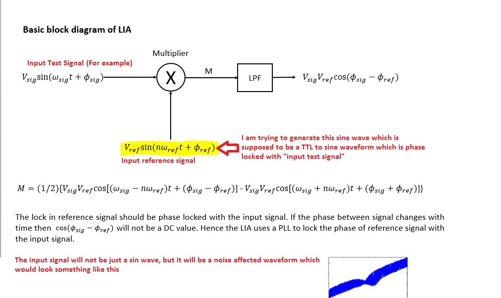
    To give you a brief detail, I am trying to use this sine wave as the reference sine wave of a LockIn amplifier. So I need a good enough sine wave having a single frequency in frequency domain.

    I am Using TM4Cxx Tiva board to do it digitally. right now I am stuck with this problem of generating sine wave of good precision.

    Rohan

  • Rohan,
    What frequency range do you need?
    What resolution (or "granularity") can you accept on your sine wave?
    And you have yet to inform how do you output the signal.
    Regards
    Bruno
  • Bruno, very well done. *LIKE*

    Robert
  • Rohan Chawhan said:
    To give you a brief detail, I am trying to use this sine wave as the reference sine wave of a LockIn amplifier.

    OK, that simplifies things a lot. The first question I would have is can you stimulate the value you are measuring with a square wave instead of a sine wave, that simplifies things a lot. It is, in fact, fairly common to use square waves with lock-ins because for many signals square waves are easier to generate.

    The key parameter, as Bruno, suggested is the sine frequency. That will determine everything else. You don't actually need a lot of precision or accuracy for this application. Stability is probably more important.

    One final thing to note, many lock-ins will provide an output reference signal that can be used.

    Robert

  • Robert Adsett72 said:
    can you stimulate the value you are measuring with a square wave instead of a sine wave

    Hi Robert,

    With the literature's that I have gone through, I have this understanding that Lock In Amplifiers use a TTL input as reference to generate a same frequency sine wave. Since I am trying to make it digital, and the frequency of reference signal  will be known to user (frequency component that needs to be extracted at the output of Lockin) I was hoping to bypass this conversion from TTL to sine. Please tell me if this is a wrong approach and why, if possible?

    Bruno,

    Frequency range - 1KHz to 20-25 KHz

    Resolution - Atleast 12 bit

    Output - not the sine directly , the filtered output of LPF of lock in would be the output. through UART

  • Rohan Chawhan said:
    With the literature's that I have gone through, I have this understanding that Lock In Amplifiers use a TTL input as reference to generate a same frequency sine wave.

    All the lock-in's I've used had both as possible inputs and as I recall would use that signal as a direct multipler, therefore the signal would have to match the excitation signal. I understand the newer ones lock to the primary frequency and generate their own internal reference.

    If you are using one of the newer lock-ins that take this approach (I think any digital lock-in) then that's an argument for using a digital reference, unless you need a sine wave for the excitation.

    Rohan Chawhan said:
    Resolution - Atleast 12 bit

    I doubt there's any advantage of going beyond 8 and maybe not beyond 6. The lock-in is doing most of the work for you. As I pointed out earlier even 1 bit is sufficient.

    Rohan Chawhan said:
    Output - not the sine directly , the filtered output of LPF of lock in would be the output. through UART

    Sorry, I don't understand.

    Rohan Chawhan said:
    Frequency range - 1KHz to 20-25 KHz

    So for decent sine reproduce-ability you need to update at least 10 to 20 times that rate and if you are generating that via PWM at least 10 times that. So two orders of magnitude ballpark minimum on the PWM or 2.5MHz.  I don't think this will turn out to be trivial

    Robert

  • BTW, if you are actually trying to build a lock-in using the TM4C I can offer some rough benchmark information.

    Robert
  • Robert, that sounds great. Please do share the information. May be I started off with a wrong foot.
  • Rohan,

    12 bit on a sin table is a piece of cake... the 4096 values can be cut down to 1024, because of the symmetry, and using floats, it would only consume 4Kb of memory. Not the worst problem.

    On the other hand, slicing a 25KHz signal into 4096 pieces is impossible at 80MHz clock. Each slice would last a bit less than 10ns... Even if all the values were precalculated in a 16Kb table and a crazily efficient DMA to UART solution was implemented, still can't be done.

    Did you mention you send this value via UART? Again another issue: even if the value could be simply sent as a float with no controlling protocol at all, that's 4 bytes which take 43us just to be transmitted, at a quite fast rate of 921600bps.

    Hope that all these won't matter, in case wise Robert's hardware considerations are valid for your requirements! Otherwise, you will need to compromise some of the requirements.

    Cheers

    Bruno
  • Hi Bruno,

    Yes I can see the problem now, I am looking at the requirements again now. These requirements that I mentioned were the Initial guess i made.

    I am looking forward for Robert's Information (assuming he has worked upon this).

    One more thing, How I am taking out the output is not my primary concern as of now (Since I saw you and Robert both raised a question on UART). I will look into that matter once I get the correct LockIn output. Any further suggestion on this is very much appreciated.

    I am attaching a block diagram of my understanding and you can comment on it:

  • Rohan Chawhan said:
    Robert, that sounds great. Please do share the information. May be I started off with a wrong foot.

    So many (too many?) here do "just that" (wrong foot - and then, "Resist (correction/steering) to the death!"      (and indeed - such "kills" helper desire/effort - likely "dooming" their project)

    These individuals (never) appear as "coach-able" as do you - this should serve you extremely well.     (both here - & "on the job" - when collaborating w/more senior colleagues...)

    Tips provided by Messrs. Robert & Bruno are quite good - yet as MCU speed proves useful - you should be aware that (other) Cortex M4 MCUs "flirt w/and exceed" 200MHz System Clock.    "Helpers" valued ideas & suggestions may serve "even more powerfully" w/your "broadened MCU investigation..."     Becoming a "superior tech. investigator" will "pay-off" for you repeatedly - in multiple areas - even (beyond) tech...

  • Hi
    I think you are quite upset about the fact that not everyone is as "Guru" as you are.

    Bruno and Robert - I really appreciate your help regarding this project, and I wish you could help even more. But as cb1_mobile suggested my knowledge regarding this area might seem to put you off, then I can understand that. Cheers
  • Greetings Rohan,

    Communication may (not) have occurred - as I hoped. I have "NO/ZERO" upset - my intent was to APPLAUD your willingness to, (possibly) "CHANGE DIRECTION" ("feet" - in your words (that IS a joke!).    You displayed a great "willingness" in accepting the guidance of "experienced" others - such proves NOT "universal" here (nor in the work-place...)

    Being "coach-able" is SO important - (some) here "are not" - and experience teaches their success - most always - will be slowed - possibly "gravely" so!     And - this is NOT YOU - not at all.    Is this now (more) clear?

    Your inviting the guidance of others - rather than "holding to an "initial idea"" ("your" idea - even if - and especially if - "your" idea) speaks very well toward your advancement & success...    Bravo!

  • Thanks ,
    I completely misunderstood your comment. Now I got your point. And I am happy that my frequent nudges are not setting anyone off here.

    Greetings,
    Rohan
  • Good Rohan - glad that's "straightened out." (resolved)

    Lost in the process (may) have been your consideration of Cortex M4 class MCUs running @/beyond 50% higher System Clocks - enhancing your efforts... (i.e. such was the "Tech investigator" suggestion...)
  • I assume from this you are implementing the block diagram.  I have implemented this.

    Overview

    • 10ksps on all channels. At 10ksps, you have an upper limit of a few hundred Hz, maybe not that high unless you use more complex filters.
    • Each channel has it's own filtering
    • Four channels use a lock-in for filtering.
    • There is in addition a frequency measurement (to generate the reference)
    • Also magnitude measurements on the four channels
    • '123 class processor running at 80MHz
    • The signals are sinusoidal so I am generating a sine reference
    • All arithmetic and intermediates are integer (fixed point)
    • Sine is generated via a lookup and interpolation. I didn't bother compressing it and used 60 points for the whole waveform. More points wouldn't affect the timing and would give minor accuracy improvements. Fewer point would probably start to degrade the accuracy and would make no difference to the timing.
    • I use a simple IIR for filtering.

    Upshot, this takes 70 to 80% of the CPU.

    Could it be further optimized? Yes

    Can it be improved by reducing the channels? Yes, But since you are not generating the reference signal but locking on to an input reference then you'll need the equivalent of one  channel for that. And keep in mind at this level of use the CPU is already overloaded.

    I think expecting 1kHz out of this is optimistic, although it might be possible. I don't see any possibility of getting to 25kHz unless you mange to be a lot more clever than I've been. Not impossible but I'd not want to assume it starting out.

    Robert

  • Bruno Saraiva said:
    Did you mention you send this value via UART? Again another issue: even if the value could be simply sent as a float with no controlling protocol at all, that's 4 bytes which take 43us just to be transmitted, at a quite fast rate of 921600bps.

    The good news here is that lock-ins update slowly. A few Hz update rate is probably sufficient, maybe 100Hz or so.

    Robert

  • Roberts,
    Yours "bullet list diagram" is an exceptional work, congrats! Really reminds me I'm a mechanical engineer!!!
    The "simple IIR filter" part caught my attention, for we are implementing new digital filters in our measurements, and seek references for implementing these folks in our Tiva's efficiently. I don't like to spin off the initial subject, but do you have resources to suggest on the matter?
    If so, I should probably open a separate thread with a more adequate subject...
    Regards
    Bruno
  • Thanks Bruno,

    Take a look at the #Bookshelf tag, you will find a reference to a free DSP guide that includes chapters on filtering. They, IIRC, do a comparison showing the equivalence of single pole IIR to a moving average. The IIR has the advantage of taking less memory, and less processing while being more adjustable.

    If you do open a separate thread, I'll giver an outline of the single pole IIR filter I use that I think gets around some of the limitations mentioned in the guide.

    Robert
  • Somehow, friend/poster Bruno - MISSED the *** LIKE *** button!      (which I - via "hacked remote access" - have just, "pushed for him!")

    And to Bruno - somewhere - on some M.E. forum - an E.E. "proclaims his love for M.E."    (maybe - or I (again) just dreamed that...)

  • Robert Adsett said:

    I assume from this you are implementing the block diagram.

    Yes Robert, I am trying to do that.

    Four channels use a lock-in for filtering.

    What are this four channels? Were you trying to take four different inputs and take out the required frequency component of each? (Sorry I didn't understand this point).

    I will have only one input which is submerged in alot of noise and the required signal I want to extract is sinusoidal as well. So looking at your further points I think that is the same you did. Although I am trying to get FOUR frequency components out of it, namely 1fx, 1fy, 2fx, 2fy (i.e. 2 harmoninc and x-y component of each)

    So overall I want to implement this as 1 input four output kinda system.

    There is in addition a frequency measurement (to generate the reference)

    The signals are sinusoidal so I am generating a sine reference

    Yes this is the point where I am stuck right now. How did you generate this reference? Can you please shed some light on this in particular?

    '123 class processor running at 80MHz

    Sine is generated via a lookup and interpolation. I didn't bother compressing it and used 60 points for the whole waveform.

    Okay this can be done. Thanks for the information. I guess this can be better judged for my application with trial and error to see the fittest values for both.

    I use a simple IIR for filtering.

    Yes I am thinking of same. with a higher order filter though. Again the complexity would be a factor to decide this. If the program takes too much calculations and time, then surely I would have  to see a optimal compromise with the order of it

     A sincere Thanks :)

  • Rohan Chawhan said:
    So looking at your further points I think that is the same you did. Although I am trying to get FOUR frequency components out of it, namely 1fx, 1fy, 2fx, 2fy (i.e. 2 harmoninc and x-y component of each)

    Yep, four waveforms or four reference frequencies (and phases), pretty much the same effort.

    Rohan Chawhan said:
    I guess this can be better judged for my application with trial and error to see the fittest values for both.

    You can easily check error with a spreadsheet.

    Rohan Chawhan said:
    If the program takes too much calculations and time

    As I noted, I don't think your desired frequency range is likely possible. I have my doubts that you'll manage to get withi an order of magnitude of it. That was the point of my post, to point out the CPU effort required.

    Robert

  • Robert Adsett72 said:
    I don't think your desired frequency range is likely possible.    I have my doubts that you'll manage to get within an order of magnitude of it.     That was the point of my post, to point out the CPU effort required.

    In "working the numbers" (as Robert has) he has "tested/examined (at/near) the "limits" - which is much valued as (often enough) a workable answer emerges, or the task is found to exceed, "proposed performance and/or capabilities!"    Making this discovery "early" - rather than "later" - is very much desired...

  • The signals are sinusoidal so I am generating a sine reference

    Yep, four waveforms or four reference frequencies (and phases), pretty much the same effort.

    Hey Robert,

    I am confused here, did you generate the reference frequencies (sine waveforms) with the micro controller itself? or did you take the reference from outside, through an ADC with 4 input channels?

    If you have generated the frequencies (which are phase locked with the test signal), then can you tell me how did you do that? Or direct me towards a correct link/document for that?

  • Rohan Chawhan said:

    The signals are sinusoidal so I am generating a sine reference

    I am confused here, did you generate the reference frequencies (sine waveforms) with the micro controller itself? or did you take the reference from outside, through an ADC with 4 input channels?

    A bit of both, I measured the frequency and generated a pure sine wave to match. I took some short cuts because of the signal I'm working with and the measurement I'm making, it's not really relevant to your issues.

    Rohan Chawhan said:
    If you have generated the frequencies (which are phase locked with the test signal), then can you tell me how did you do that? Or direct me towards a correct link/document for that?

    Surely this is the simplest case? You generate the waveform and put it out on a pin to stimulate the signal. You use that same waveform as your internal reference.

    Are you reducing your performance requirements?

    Robert