This thread has been locked.

If you have a related question, please click the "Ask a related question" button in the top right corner. The newly created question will be automatically linked to this question.

How to reset/prescale the timer?

At the end of the post is my codes, where ConfigureUART can be found in most TI examples so I didn't include, also there are duplicated headers files due to copy/paste but it would have any negative effect.

The program runs fine and timer counts up.

My questions

1) How do I reset the counter? I tried to disable and enable timer, and it had no effect

2) How do I set up the prescaler? I used TimerPrescaleSet and it had no effect


Thanks for your time and pointer!

>>>>>>>>>>>>>>

#include <stdint.h>
#include <stdbool.h>
#include "inc/hw_ints.h"
#include "inc/hw_memmap.h"
#include "inc/hw_types.h"
#include "inc/hw_uart.h"
#include "inc/hw_ssi.h"
#include "driverlib/fpu.h"
#include "driverlib/gpio.h"
#include "driverlib/interrupt.h"
#include "driverlib/pin_map.h"
#include "driverlib/rom.h"
#include "driverlib/ROM_map.h"
#include "driverlib/sysctl.h"
#include "driverlib/systick.h"
#include "driverlib/uart.h"
#include "driverlib/udma.h"
#include "driverlib/ssi.h"
#include "utils/cpu_usage.h"
#include "utils/uartstdio.h"
#include "utils/ustdlib.h"

#include "inc/hw_emac.h"
#include "inc/hw_memmap.h"
#include "inc/hw_types.h"
#include "driverlib/debug.h"
#include "driverlib/emac.h"
#include "driverlib/flash.h"
#include "driverlib/interrupt.h"
#include "uip/uip.h"
#include "uip/uip_arp.h"
#include "httpd/httpd.h"
#include "dhcpc/dhcpc.h"
#include "drivers/pinout.h"
#include "driverlib/adc.h"
#include "inc/hw_adc.h"
#include "driverlib/timer.h"
#include "driverlib/gpio.h"

#include <stdint.h>
#include <stdbool.h>
#include "inc/hw_memmap.h"
#include "inc/hw_types.h"
#include "inc/hw_gpio.h"
#include "driverlib/debug.h"
#include "driverlib/fpu.h"
#include "driverlib/gpio.h"
#include "driverlib/pin_map.h"
#include "driverlib/rom.h"
#include "driverlib/sysctl.h"
#include "driverlib/timer.h"
#include "driverlib/uart.h"
#include "driverlib/rom_map.h"
#include "driverlib/gpio.h"
#include "utils/uartstdio.h"

int main(void) {
    unsigned int val;

    g_ui32SysClock = MAP_SysCtlClockFreqSet((SYSCTL_XTAL_25MHZ |
                                             SYSCTL_OSC_MAIN |
                                             SYSCTL_USE_PLL |
                                             SYSCTL_CFG_VCO_480), 120000000);


    MAP_SysCtlPeripheralEnable(SYSCTL_PERIPH_TIMER1);
    MAP_SysCtlPeripheralEnable(SYSCTL_PERIPH_GPIOA);

    MAP_GPIOPinConfigure(GPIO_PA2_T1CCP0);
    MAP_GPIOPinTypeTimer(GPIO_PORTA_BASE, GPIO_PIN_2);

    ConfigureUART();

    TimerConfigure(TIMER1_BASE, TIMER_CFG_A_CAP_COUNT_UP);

    TimerControlEvent(TIMER1_BASE, TIMER_A, TIMER_EVENT_POS_EDGE);
    TimerPrescaleSet(TIMER1_BASE, TIMER_A, 255);
    TimerEnable(TIMER1_BASE, TIMER_A);

    while (1)
    {
        val = TimerValueGet(TIMER1_BASE, TIMER_A);
        UARTprintf("Timer1A: (%u) \n", val&0xffff);
    }


}

  • Hello David,

    On disabling the timer, try writing to the GPTMTAV register.

    Regards

    Amit

  • I am not trying to disable it, but to reset the count to zero


    Also, I need to control the prescaler.

    Thanks!

  • Isn't that what TimerLoadSet does if you set it to zero?

    Robert

  • I thought so too, but it didn't work

  • Interesting, I haven't as of yet needed to do this.  Someone must have though.  If that indeed doen't work the Tivaware documentation is in need of an update.

    Hmm, looks like the load register is actually the reload register.  You have to write to the value register from the looks of the chip documentation. And it looks like the TIVAWare API doesn't provide an interface for that although the chip documentation does say that it is a writeable register.

    Maybe someone else has a better idea?

    Robert

  • Hello Robert,

    The Load Register is actually the register for the limits of the up count or down count. The Value Register is what affects the run time changes to the counter

    Regards

    Amit

  • That's how I thought it must be behaving after David's report and re-reading the TIVAWare documentation.  Which then lead me to check the chip documentation.

    The TIVAWare documentation can, unfortunately, be read as updating the value register since it mentions that it also/still updates the register if the timer is running, a qualification that is normally only needed for the value register.  Reload registers are usually updateable whether the timer is running or not.


    Robert

  • Based on Amit's comment, HWREG(TIMER1_BASE+0x50)=0; will do the trick to reset the counter (if you know the API in TiVaware, please let me know)

    but HWREG(TIMER1_BASE+0x38)=25; still does nothing to affect the prescaler

    Any suggestion on the prescaler (setting and resetting)?

  • I would expect to have to stop the timer before changing the prescaler but admit I haven't checked.

    Robert

  • Hello David,

    I would think it to be disable, update the prescalar and then enable. But to confirm it would need to run some tests as well.

    Regards

    Amit

  • I have tried that already and the prescaler simply has no effect no matter what I assigned to it

    TimerDisable(TIMER1_BASE, TIMER_A);


    TimerPrescaleSet(TIMER1_BASE, TIMER_A, 255); //No effect
    HWREG(TIMER1_BASE+0x50)=0; //this indeed resets the counter
    //HWREG(TIMER1_BASE+0x38)=255; //no effect

    TimerEnable(TIMER1_BASE, TIMER_A);

  • Are you sure the prescaler is available in your timer configuration?  I know the chip I'm using documents restrictions based on timer width.


    Robert


  • Amit Ashara said:

    The Load Register is actually the register for the limits of the up count or down count. The Value Register is what affects the run time changes to the counter


    Interestingly, my chip documentation matches the TIVAware documentation but only for the count down case.  For count up writing to the value register is required.


    That's a subtle point that should probably be repeated in the TIVAware manual.


    Robert

  • Might the answer be that this MCU - in this particular timing mode - employs the prescaler as a, "Timer Extension" - which is outside of your (and most here's) expectation.

    If true - the prescaler will be "hit" only upon your timer's overflow - thus will not cause the effect I suspect that you seek...

  • I also considered such case since it was mentioned in some modes

    but the prescaler register's value never change when counter overflows, it retains whatever I assigned to it, and it has no effect on anything that I can see

  • I am using edge count on 1294, and Table 13-3 t suggests this mode has an 8-bit prescaler + 16-bit counter

  • As you have awareness of that (unwanted) timer extension behavior might the order of prescaler & timer set-up, config. & enabling be critical?

    Like Robert - I've not used in awhile - yet recall some such sensitivity - reported here - long past...

    In addition - we note that you, "count up" and our MCU manual warns that this limits prescale use:

    "Note that when counting down in one-shot or periodic modes, the prescaler acts as a true prescaler and contains the least-significant bits of the count. When counting up in one-shot or periodic modes, the prescaler acts as a timer extension and holds the most-significant bits of the count. In input edge count, input edge time and PWM mode, the prescaler always acts as a timer extension, regardless of the count direction."

  • Hello All,

    Well there is one issue with the code though. The documentation mentions that the Timer Capture Count Mode is a 16-bit mode but the code is configuring it for 32-bit mode.

    Secondly, the Prescale in this mode (up count) specifically is a 8-bit extender and it seems that it cannot be loaded since the count from 0 to the 24-bit value is what is being expected. Yes, it an be argued that it is a bug/document does not state it as the base register can be loaded and not the extender register. This will take some digging to find out.

    Regards

    Amit

  • Amit, could you tell me how to config it to 16-bit mode? thanks

  • I tried to force the counter to 16-bit based on my reading of page 976, but the result is the same, no prescaler, neither real prescaler nor extension when overflow

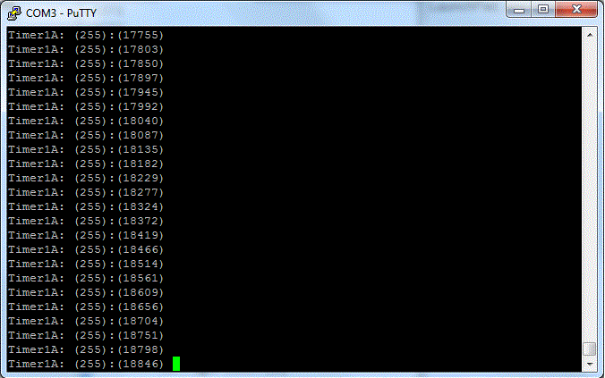
    Output:

    >>>>>>>>>>>

    int main(void) {
    unsigned int val, val2;

    g_ui32SysClock = MAP_SysCtlClockFreqSet((SYSCTL_XTAL_25MHZ |SYSCTL_OSC_MAIN |SYSCTL_USE_PLL |SYSCTL_CFG_VCO_480), 120000000);


    MAP_SysCtlPeripheralEnable(SYSCTL_PERIPH_TIMER1);
    MAP_SysCtlPeripheralEnable(SYSCTL_PERIPH_GPIOA);

    MAP_GPIOPinConfigure(GPIO_PA2_T1CCP0);
    MAP_GPIOPinTypeTimer(GPIO_PORTA_BASE, GPIO_PIN_2);

    ConfigureUART();


    TimerConfigure(TIMER1_BASE, TIMER_CFG_A_CAP_COUNT_UP);
    HWREG(TIMER1_BASE)=4;

    TimerControlEvent(TIMER1_BASE, TIMER_A, TIMER_EVENT_POS_EDGE);

    TimerDisable(TIMER1_BASE, TIMER_A);

    TimerPrescaleSet(TIMER1_BASE, TIMER_A, 255);
    HWREG(TIMER1_BASE+0x50)=0;
    TimerEnable(TIMER1_BASE, TIMER_A);

    while (1){

    val2 =HWREG(TIMER1_BASE+0x38);
    val = TimerValueGet(TIMER1_BASE, TIMER_A);
    UARTprintf("Timer1A: (%u):(%u) \n", val2&0xff, val&0xffff);
    }


    }

  • Hello David

    For 16-bit mode it is

    TimerConfigure(TIMER1_BASE, (TIMER_CFG_SPLIT_PAIR|TIMER_CFG_A_CAP_COUNT_UP));

    instead of

    TimerConfigure(TIMER1_BASE, TIMER_CFG_A_CAP_COUNT_UP);

    Regards

    Amit

  • Tried it, the result is the same.


    Prescaler has no effect, and it doesn't serve as extension either (I read val2 =HWREG(TIMER1_BASE+0x38);)

    TIMER_CFG_SPLIT_PAIR = 4, so I got a feeling it is the same as my previous test with HWREG(TIMER1_BASE)=4

  • While struggling with prescaler/extension, this line also caught my attention:

    On Page 962, 13.3.3.3, of 1294 data sheet:

    ....Based on this criteria, the maximum input frequency for edge detection is 1/4 of the frequency.


    Since the "the" was not clear here, I would like to have your clarification. In my codes, I used

    g_ui32SysClock = MAP_SysCtlClockFreqSet((SYSCTL_XTAL_25MHZ |SYSCTL_OSC_MAIN |SYSCTL_USE_PLL |SYSCTL_CFG_VCO_480), 120000000);

    So the maximum input frequency is 1/4 of which clock, 120Mhz? 25Mhz? or what?

  • Hello David,

    I made some code changes and now it works. In the data sheet the conditions for the timer in up count is mentioned as GPTMTnILR > GPTMTnMATCHR and GPTMTnPR > GPTMTnPMR.

    Also the read has to be done in the same register as TimerValueGet namely GPTMTnR

        TimerConfigure(TIMER1_BASE, (TIMER_CFG_SPLIT_PAIR|TIMER_CFG_A_CAP_COUNT_UP));

        TimerControlEvent(TIMER1_BASE, TIMER_A, TIMER_EVENT_POS_EDGE);
        TimerLoadSet(TIMER1_BASE, TIMER_A, 15);
        TimerMatchSet(TIMER1_BASE, TIMER_A, 1);
        TimerPrescaleSet(TIMER1_BASE, TIMER_A, 15);
        TimerPrescaleMatchSet(TIMER1_BASE, TIMER_A, 4);
        TimerEnable(TIMER1_BASE, TIMER_A);

        while (1){
            val = TimerValueGet(TIMER1_BASE, TIMER_A);
            UARTprintf("Timer1A: (%u):(%u) \n", ((val&0xff0000) >> 16), val&0xffff);
        }


    Regards

    Amit

  • Thanks for your reply!

    [Post removed, please see my following post for more info]

  • Hi Amit,

    It seems the meaning of TimerLoadSet, MatchSet, PrescaleSet and PrescaleMatchSet are all redefined here for the function. Could you explain the function of each one in your codes?


    Thanks!

  • After some tests, I believe the following is true

    1) As Amit point out, we must have TimerLoadSet>TimerMatchSet, and TimerPrescaleSet>TimerPrescaleMatchSet to use the up counter

    2) TimerLoadSet doesn't have any control as long as it is greater than TimerMatchSet

    3) TimerMatchSet and TimerPrescaleMatchSet together determine the (interrupt) trigger condition

    4) TimerPrescaleSet doesn't have any control as long as it is greater than TimerPrescaleMatchSet

    5) TimerPrescaleMatchSet determines the max value of the extension before it wraps around to 0

    6) Due to 5), the highest extension is only 254

    7) The max clock rate is 1/4 of 80Mhz if that is what we setup the CPU to run at

    8) To reset counter, HWREG(TIMER1_BASE+0x50)=0;

  • Hello David,

    I think we need to find a way to get this into the data sheet.

    Regards

    Amit

  • Hi David,

    I have found TM4C1294 for low edge counts PreScaler only needs to be set if the timer is used in 24 bit up count mode. Otherwise it remains in 16 bit up count mode with no wrapping of count high order bits 23:16.

    Also TnILR must to be set above TnMatchCHR or the timer will stop and not reload once it reaches MatchCHR. To state TnILR does not have any control sorry to disagree with that part and find it must be set above MatchCHR for the total number of expected edges to capture. Where as in up count edge time mode TnMatchCHR has no meaning and can be omitted since the timer keeps counting past TnILR after the capture interrupt triggers.

    You might try using hex value 0x00FF for the value in PreScaler versus 255 actually 511 not 254 for the full bit field. Then you get 00FF.XXXX.XXXX for the total edge count value returned in both TnV + TnR registers. Otherwise in 16 bit edge count mode TnV holds the match count value.

    11.10.15:

    511 was not correct when starting from bit 15 bit position 16 counting from 1 but 0x00FF gives the full extra 8 bits for capturing the maximum of 140ms edge times.

  • Now please help me with my problem to get any timer counting edges from 107-210Hz. Trying to compare the number of pervious edges captured with number of new edges seems a daunting task without dead locking the timer when the edges frequency rapidly increases past TnMatchCHR. That might be an anomaly of the timer or even some kind of errata.

    In edge capture mode the up count timer timeouts/interrupts appear to be disabled. Possibly since the timer is said to automatically reload with 0x0000 when TnMatchCHR is reached versus down count reload of TnILR simply stops. In my view that infers we have to quickly reload TnILR if the timer ever exceeds edge counts matched by TnMatchCHR from possibly missing interrupt cycles in real time edge changes. Upon TnMatchCHR asserting interrupt timer then auto reloads 0x0000 and count up to the previous TnMatchCHR value.

    That is unless the real time edge count exceeds TnMatchCHR then once again TnILR may need to be asserted order to reload the timer establishing a boundary above TnMatchCHR a sort of mock reset refreshing the timer upper count limit if ever it was forced lower in a previous match count event, reloading timer 0x0000. Otherwise how can we once again capture higher edge counts above a new and lower TnMatchCHR value. Unless in my view both values are made dynamic in the interrupt handler. Seems to Infer we have to keep the values moving in both direction both registers (if counts </> then reload new counts). That may be where my SW has gone amuck since it only counts edges up or down to a specific frequency range so bandwidth is very narrow. When I widen the range the timer freaks out.

    The text mentions down count match and up count reload with 0x0000 and timer continues counting to where exactly? and what if's are not covered. It seems to me TnILR plays a valid role in edge count events captured or not by TnMatchCHR.
  • Sorry, but I am deep in the water of another time critical project.... may be Amit can look into this
  • Seems my problem is related to the TnMatchCHR value after all. If reset on the next timer cycle to a value above 0x0001 the CAMMIS interrupt triggers but the timer match set load will not update the timer with new matched edge value. So edge count mode appears to count only 2 edges very well but beyond that has issues in the TnMatchCHR reload.

    The main point being made above and I have witnessed was any time TnILR value becomes lower than TnMatchCHR value in up count the timer dead locks.
  • Hello BP101,

    Is that why you have raised the following post?

    e2e.ti.com/.../467999

    Regards
    Amit
  • Yes Amit,

    My dynamic floating edge count 4 edge gap band didn't work much better to get RPM above 253 but counts much longer before debug registers brown out. The count would grow much larger and keep 4 edges spacing between ILR and matchCHR but the timer debug view could not keep up with accelerating edge counts same for MIS. The odd thing is in 2 edge capture the registers do not brown out they simply keep counting during edge accelerations.

    The debug registers would return to default values and as the edge counts returned into the matchCHR range debug registers start counting once again. The RPM readout tick handler variable flip flop returns the speed to zero when the edge counts stop and pick up when counts in the interrupt loop return.
  • BP101 said:
    My dynamic floating edge count 4 edge gap band

    Might this be made (more) understandable & inviting through the use of "bullet points" with each item (somewhat) detailed & justified.  (i.e. as to role & intent)

    Colorful language has its place - but (perhaps) not here - especially when seeking complex (& fringe) tech support...

    After digesting that 8 word cascade - responders must ponder "where to begin!"    KISS rules - especially so when seeking diagnostic support...

  • Albeit that was a reply to Amit who had been briefed on the method of gap band edge counting.

    The point escaping naming convention is that edge counting from an disconnected PIOSC or SYSCLK clock source proves futile given the configuration schema example in datasheet is followed. Gap banding was only one method attempted after basic edge counting failed. Gap banding counts was explained in prior posts as accumulating said amount of edge captures held captive inside a rising timer count. IE: exceeding TnILR 0x0008 TnMatChr 0x0004, Gap banding TnILR 0x0384 TnMatChr 0x0380 contains the same 4-5 edges during TnCMMIS interrupt cycle. In theory up counting timer resets 0x0000 after TnMatchr.

    Doesn't matter how high the count is extend into abstract time as the exact same gibberish data is read back TnR register. There is no foundation to build upon so the wall simply crumbles. There is no disclosure in datasheet that edge count mode requires prescaler time. Only requirements are 2 clock cycles of setup timer for the input edge to remain low or high in that pending edge being captured by CCP pin.

    So something ain't right if can't compare a previous edge count in time with a present edge count and develop a span of rising counts inside TnCMMIS handler. Injecting 25kHz into the same CCP pin gives the very same gibberish count data appearing to have the same reported RPM as 100-210Hz. The idea tabled; How to mimic hog counting method of the QEI velocity timer using edge count or edge time to achieve that goal. The velocity timer times out or expires driving an interrupt so SW can get the previous hog count and convert edges/second into RPM. That in abstract seems simple but in hind sight removing the previous GPIO edge time interrupt first synchronizing the external signal source input with SYSCLK from that code and it may have pitfalls in time extraction.

    What say you to that?
  • Hello BP101

    I was going through the errata and I think GPTM#15 ,may be the cause of the issue that you are seeing where an extra count value messes up the counting of the edges.

    Regards
    Amit
  • Hi Amit,

    I tried to vary the range from 2,3, 4, 5,6,8 edges and didn't see much difference in the values being returned in HWREG reads of TnR or TnV. It seems plausible we shouldn't require prescaler in edge count mode since the actual edge transition triggers CCP input gates increment timers count so time is not important and the counter is free running between edge counts? That is not being explained in the test.
    Or does the time from one edge to the next in milliseconds have to be relative to the free running count? It seem the counts in TnV, TnR were cycling with both edges yet not very fast.

    Seemingly that is not true in edge time mode. Prescaler might just be required per table 13-5 order to sync with slow edge timings presented to the timer by extending the count range as a factor of time. Prescaler register 14 attempts to contradict that and states in all other modes it only extends the bit range for 16 bit 1/2 mode. Seems as if two different views were being related in the dynamic of the timer behavior relating to prescaler. In my view it seems as if both table 13-5 and REG14 do not concur - it negates edge time mode relative to table 13-5.

    Interesting is the taco signal is a square wave and datasheet shows a saw tooth wave form in edge time mode figure 13-3. That is not a saw tooth wave form rather illustrates time as a factor of slope. Just the job for prescaler to extend the edge sample time window by increasing the free running timer count time.

    Oddly in single stepping the HWREG read of TnR or TnV often exceeds a long for no apparent reason. That was with prescaler disabled. Now set up in edge time capture mode, prescaler set 0x0014 or 120Mhz SYSCLK 20Tc*.548528ms = 10.9ms for slowest edge time just below 100Hz. The fan taco signal is running a constant slow speed with minimal leading edge jitter and capturing only the positive edge.
  • Hello BP101

    The saw tooth is a decrementing down count in edge time mode (nite the Y-axis is the count value)

    To measure a slow Tach input, I would use the number of Tach pulses per revolution of the fan as the match value to assert interrupt where the value of the timer in input edge time shall be read out. The capture shall be kept at either the rising or falling edge. Once the capture edge is over, a update shall be performed to reload the timer values to both the sub timers for the next periodic capture.

    Regards
    Amit
  • Hi Amit,

    Trying exactly that process in the time capture interrupt handler. Except the reload from the previous captured edge time becomes a difference between 2 edge times. Previous saved edge time data is read from TnR and or either compared to the present and actual TnR. or TnV value. Either way the conversion data is the same in both timer modes almost to the number. Multiplying the edge time or edge counts conversion result does not increase nor decrease the reported RPM it remains under 253 no matter the edge time or count.

    Seems as if GPTM#13 is always present even when there is no alternate clock source. When it has been set either way the TnR data does not  change values being returned. In edge time mode the TnV, TnR registers are counting into the high  0x00XX.XXXX but the HWREG read back is very low values and or more often above uint32_t so the ui32 value must be wrapping backwards when that happens hard to tell in single stepping if that is true.

    Last step prior to exiting interrupt:

    /* Reset the reload time TnILR value. */
    ROM_TimerLoadSet(TIMER4_BASE, TIMER_A, ulNewEdgeTime);
    HWREG(TIMER4_BASE + TIMER_O_TAMR) |= !TIMER_TAMR_TAILD;

  • Hi Amit,

    >Seems as if GPTM#13 is always present even when there is no alternate clock source.

    Confirmed setting a GPIO port input with interrupt into the same handler after disabling edge timer 4A code. Then read back the PWM timer 5A TaR and TaV values using the GPIO pin interrupt for taco and get the very same speed data as timer 4A was producing in both edge count and edge time mode.

    We don't need to set a CCP event capture type in edge count or edge time mode?
    What else in configuration might cause TnR and TnV values to be wacko besides #13?
  • Hello BP101,

    If the clock source is not alternate, then there is none.

    Anyways this thread along with other has prompted me to propose the Application Note on 4 wire Fan controller using timer.

    Regards
    Amit
  • Hi Amit,

    >If the clock source is not alternate, then there is none

    Agree there shouldn't be #13 yet there appears to be similar behavior in the production run TM4C1294NCPDTi3 for timer 4 and 5.

    Otherwise possibly HWREG macro is not actually returning the register results from GPTM_TnR & TnV.

    Can you confirm this is the case or not?


  • Hello BP101,

    Then what does it seem to return shall help us identify the cause.

    Regards
    Amit
  • Hi Amit,

    The same random data is retuned for very low edge counts TnR 0x0001 - 0x0004 as is for the register edge time values producing much higher timer counts in TnR up to as high as 0x001A.FFFF.FFFF. So it seems the register results are the same even upon reading PWM timers TnR even if using a GPIO interrupt to read the registers.

    PWM duty cycle changes only load TnMatchr and don't read TnR or TnV, that is why it wouldn't have been noticed.

    The TnCAMIM or TnCAEIM interrupts edge time or edge count appear sychro with edge transitions on CCP. Not able to know for sure when the count is changing relative to the edges. Taco output is open collector input CPP and datasheet no mention other than TTL compatibility with the GPIO input.
  • BP101 said:
    Not able to know for sure when the count is changing relative to the edges

    Does not KISS simply, easily & quickly "spring" to the rescue?   (again)

    Surely this will reveal:

    • Feed the CCPx pin with a "known good" input signal
    • Toggle that input signal
    • Simply loop on the counter's value - stopping upon change.

    It should be possible to "time stamp" the input signal's toggle.

    It should be possible to "time stamp" the counter value's change.   Simple subtraction and accommodation of MCU's clock speed should pinpoint.

    One would think (and hope.)

  • Hello BP101

    What is the Tach Pull Up value? If it is pulled up to 3.3V then it would work fine from compatibility

    Regards
    Amit
  • Morning Amit,
    CB1 has the same idea I just came up before seeing his post above, accept togging CCP is not a function of edge time/capture modes. Counting the actual match count interrupts and display via high speed USB printouts is.

    A simple test to count the number of TnCMMIE interrupts reveal edge counts up to TnMatchr=60 are turtle slow at 100hz. The timer is not counting or possibly capturing edges fast enough even at 100Hz regardless of the values in TnV or TnR.

    Looping 25Khz into the CCP edge count input of course the match interrupt rate increased dramatically. That is not revealing the timers actual edge count capture frequency unless it can be some how measured by a frequency counter. Perhaps there is a condition of slipping edges going on in the capture engine?
  • That synopsis deserves a green flag of appreciation sir!

    GREEN GREEN GREEN