This thread has been locked.

If you have a related question, please click the "Ask a related question" button in the top right corner. The newly created question will be automatically linked to this question.

JTAG problem for Custom Board with TM4C129XNCZAD

Other Parts Discussed in Thread: TM4C129XNCZAD, LMFLASHPROGRAMMER

Hi,

 I custom-designed the board with TM4C129XNCZAD, and I have trouble to connect it via JTAG.

How I am trying to do that is using DK-TM4C129X. Previously I succeeded that with two DK-TM4C129X, but for now, I can't connect it via JTAG.

I'm using LM Flash Programmer (Build 1588), and I can't even do hardware reset for new custom board.

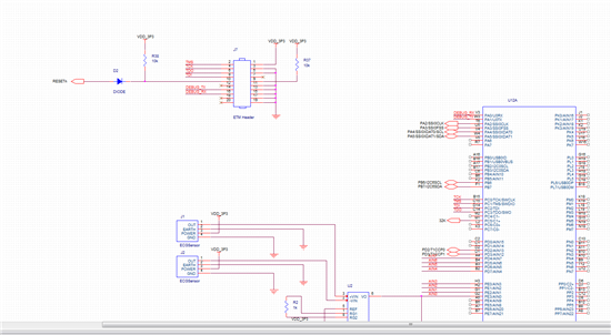
I mimicked the interface of DK-TM4C129X on my custom board, which is 20 pin ETM interface.

I know my question is too naive, but if you find anything I am overlooking, please reply me.

Thanks.

  • Hello Minho,

    How are you connecting the JTAG debugger to the custom TM4C129 board. Can you please list the pin mapping from the JTAG debugger to the custom board's 20-pin header.

    Also if you can send over the schematic section from the 20-pin header to the device, it will be useful

    Regards

    Amit

  • Hi,

     I'm just using DK-TM4C129X as a debugger. From the datasheet, I thought DK-TM4C129X can be used to program

    the external board, and I did it to program the other DK-TM4C129X 

    Pin 1 of DK-TM4C129X was mapped to the pin 1 of 20 pin connector, and equal for the other pins.

    Thanks for your kindness to answer my naive question.

  • Hello Minho,

    Have you made any changes on the DK-TM4C129 so that the debug out from the DK-TM4C129 can be connected to the custom board? The reason is because the TDO from your board may be interfering with the TDO from the TM4C129 device on the DK.

    Also, can you confirm the JTAG not working as per the checklist in the following thread

    http://e2e.ti.com/support/microcontrollers/tiva_arm/f/908/t/374640.aspx

    Regards

    Amit

  • Hi Amit,

     I just pulled out headers to disconnect that from TM129X on DK-TM4C129. What I found now was that initially TMS is high, but when the debugger tried to connect it by pulling down the signals, TMS became low.

    In my custom board, I didn't put any pull up resistor on TMS, TCK, TDI, and TDO because I thought it might be implemented inside TM4C129XNZAD. Can it be a serious problem?

    Thanks.

  • We note NO (zero) pull-up Rs on any of the JTAG lines.  Relying upon MCU's internal ones (usually very high in resistance) has been shown to reduce signal levels & round signal edges - neither "optimal" for bringing up a new, custom board.  (where "anything" may be faulty - plague your efforts)

    Cost/size savings of 4 06-03 pull-up Rs has been "swallowed" by your lost time/effort - never to be recovered...  Is this wise?

  • Hello Minho

    The TM4C129 devices have a weak pull up. This is a ~30K pull up. On a good routed board this will not cause an issue, but if you want to do a custom board, it would be preferred to have an external pull up.

    While this may contribute to the issue you are facing it still may not be the only contributor

    1. I removed the header pins on DK-TM4C129 for TMS, TCK, TDI. TDO and Reset and blue wired to a small custom board that has JTAG

    2. I made sure that the GND between the DK and my custom board is connected

    3. The I ran LMFlashProgrammer to erase and verify flash and it worked.

    4. My custom board has external OSC of 25MHz and VDDC showing 1.2V

    Can you do the checks as well on your side.

    Regards

    Amit

  • Because this is my first PCB design, I made lots of mistake. I didn't try to minimize the size of board.

    I just mimicked DK-TM4C, and it dosen't have external pull-up resistor.

    Thanks for your advice

  • Thanks a lot. I'll follow your suggestion.

    What do you think about my second explanation that TMS was high, but turned low once the debugger tried to program it?

  • Hi Amit,

     I check that VDDC is stable at 1.2V, and because I'm using crystal instead of OSC, I can't verify whether XTAL works at 25MHz. When I probed it, it oscillates very weakly around 1V.

    Can you suggest how I can probe the oscillation of 25MHz crystal?

     As I told you, I didn't put any external pull-up resistor, and as I probed them, there were lots of fluctuation on JTAG signal. I suppose it will be mitigated by adding pull-up resistor.

    Thanks for your advice, and it is very helpful.

  • Amit Ashara said:
    On a good routed board this will not cause an issue

    And - who is to satisfactorily "judge" what qualifies as, "good routed?"  (the rushed, 1st time board designer?)

    Over the years - we've seen > 50 such "well designed" boards (our judgment) fail due to reliance upon MCU's "weak" internal pull-ups.  (across many ARM MCUs - many makers!)

    The "risk-reward" for reliance upon "internal pull-ups" makes little sense - imho.  Even a "well designed" board - operating w/in an RF or bit noisy environment - is more likely to suffer signal loss/distortion when using "internal pull-ups."  (and - w/the universal presence of cells, other signal sources - this problem is destined to expand)

    Even worse - internal pull-ups may work (as you state) in "pristine environments" - even in offending ones - "most of the time."  But (and an important but) may fail at a critical time - when the client really needs to debug/download - and because it's worked in the past - client is "lulled" into thinking, "all is well."  (when really - it is NOT!  He/she's been lucky - signals have long been, "on the edge!")

    Cost/size "savings" of 4 06-03 pull-ups is unlikely to be required by 99.9% here.  Loss of users' time/efforts & morale - via even occasional LOS (loss or distortion of signal) argues strongly in favor of external (proper) pull-ups...

  • Hello cb1,

    That dawned to me after the poster mentioned that it was the first board they had made...

    Regards

    Amit

  • Hi cb1,

     If the reference board had pull-up resistors, I would have done that. Anyway, as I probed TMS, TCK, I found lots of ringing there, and I hope adding pull-up resistor can be helpful.

  • You need to properly "weigh" the risk/reward of using (proper) always present - pull-up Rs vs. the "hoped for" signal integrity provided by (MCU's internal) resistors "outside" of normal/customary JTAG specification.  (and which may be subject to "disconnect" via software - deliberate or unintended...)

  • Hi,

     I appreciate your advice. What I found was that forcing 25MHz clock with function generator fixed every problem. I doubt why the 25MHz osc on board doesn't work. I hope my post would be helpful for others experiencing the same problem.

  • Hello Minho,

    In the past we have noticed that the crystal not being mounted well has caused grief during connect. Now you mention that it is a Oscillator (and not a crystal). Any specific on the data sheet for the same would be useful.

    Regards

    Amit

  • Hi Amit,

     Sometimes, I make mistake between osc and xtal. Exactly, I used xtal, not osc. and my case is very close to what you mentioned. Xtal was assembled at the PCB company. I'm not sure about not being mounted on board. I built 3 boards, and all the boards have the same problem.

    Thanks.

  • Hello Minho,

    And since this was a 25MHz crystal, was the Rs and C1,C2 connected to the crystal as per the Crystal Specification in the electrical section of the data sheet?

    Regards

    Amit

  • I guess that might be the critical fault I made in the custom board. From the reference board, I found that Rs is 0 ohm, so I omitted that. Thanks for your point.

    Thanks.

  • Hello Minho,

    Please do take care of the capacitors as well as per the table in the electrical section for the crystal mentioned/used.

    Regards

    Amit