This thread has been locked.

If you have a related question, please click the "Ask a related question" button in the top right corner. The newly created question will be automatically linked to this question.

Customized TIVA board: I2C is not working

Other Parts Discussed in Thread: TM4C129XNCZAD, TM4C1294NCPDT, TM4C1292NCPDT

Hello,

We are working on a customized TIVA board. The TIVA is connecting via ICE and Etherent , UART1 are working OK.

The attached code was created by PinMux utility in order to initialize I2C5,7

But when we sent data via I2C5 (and 7) we saw nothing with scope. No clock and no data

Can you tell what are we doing wrong ?

What should we check using scope or code ?

We used the same code on TI's TIVA board. In this board we used I2C6 only.

Best regards,

Z.V

6201.Tiva.c
//*****************************************************************************
// Copyright (c) 2014 Texas Instruments Incorporated.  All rights reserved.
// Software License Agreement
// 
//   Redistribution and use in source and binary forms, with or without
//   modification, are permitted provided that the following conditions
//   are met:
// 
//   Redistributions of source code must retain the above copyright
//   notice, this list of conditions and the following disclaimer.
// 
//   Redistributions in binary form must reproduce the above copyright
//   notice, this list of conditions and the following disclaimer in the
//   documentation and/or other materials provided with the  
//   distribution.
// 
//   Neither the name of Texas Instruments Incorporated nor the names of
//   its contributors may be used to endorse or promote products derived
//   from this software without specific prior written permission.
// 
// THIS SOFTWARE IS PROVIDED BY THE COPYRIGHT HOLDERS AND CONTRIBUTORS
// "AS IS" AND ANY EXPRESS OR IMPLIED WARRANTIES, INCLUDING, BUT NOT
// LIMITED TO, THE IMPLIED WARRANTIES OF MERCHANTABILITY AND FITNESS FOR
// A PARTICULAR PURPOSE ARE DISCLAIMED. IN NO EVENT SHALL THE COPYRIGHT
// OWNER OR CONTRIBUTORS BE LIABLE FOR ANY DIRECT, INDIRECT, INCIDENTAL,
// SPECIAL, EXEMPLARY, OR CONSEQUENTIAL DAMAGES (INCLUDING, BUT NOT
// LIMITED TO, PROCUREMENT OF SUBSTITUTE GOODS OR SERVICES; LOSS OF USE,
// DATA, OR PROFITS; OR BUSINESS INTERRUPTION) HOWEVER CAUSED AND ON ANY
// THEORY OF LIABILITY, WHETHER IN CONTRACT, STRICT LIABILITY, OR TORT
// (INCLUDING NEGLIGENCE OR OTHERWISE) ARISING IN ANY WAY OUT OF THE USE
// OF THIS SOFTWARE, EVEN IF ADVISED OF THE POSSIBILITY OF SUCH DAMAGE.
//
// This file was automatically generated by the Tiva C Series PinMux Utility
// Version: 1.0.4
//
//*****************************************************************************

#include <stdint.h>
#include <stdbool.h>
#include "Tiva.h"
#include "inc/hw_types.h"
#include "inc/hw_memmap.h"
#include "inc/hw_gpio.h"
#include "driverlib/sysctl.h"
#include "driverlib/pin_map.h"
#include "driverlib/rom_map.h"
#include "driverlib/gpio.h"

//*****************************************************************************
void
PortFunctionInit(void)
{
    //
    // Enable Peripheral Clocks 
    //
    MAP_SysCtlPeripheralEnable(SYSCTL_PERIPH_I2C7);
    MAP_SysCtlPeripheralEnable(SYSCTL_PERIPH_I2C5);
    MAP_SysCtlPeripheralEnable(SYSCTL_PERIPH_GPIOA);
    MAP_SysCtlPeripheralEnable(SYSCTL_PERIPH_GPIOB);

    //
    // Enable pin PB4 for I2C5 I2C5SCL
    //
    MAP_GPIOPinConfigure(GPIO_PB4_I2C5SCL);
    MAP_GPIOPinTypeI2CSCL(GPIO_PORTB_BASE, GPIO_PIN_4);

    //
    // Enable pin PB5 for I2C5 I2C5SDA
    //
    MAP_GPIOPinConfigure(GPIO_PB5_I2C5SDA);
    MAP_GPIOPinTypeI2C(GPIO_PORTB_BASE, GPIO_PIN_5);

    //
    // Enable pin PA4 for I2C7 I2C7SCL
    //
    MAP_GPIOPinConfigure(GPIO_PA4_I2C7SCL);
    MAP_GPIOPinTypeI2CSCL(GPIO_PORTA_BASE, GPIO_PIN_4);

    //
    // Enable pin PA5 for I2C7 I2C7SDA
    //
    MAP_GPIOPinConfigure(GPIO_PA5_I2C7SDA);
    MAP_GPIOPinTypeI2C(GPIO_PORTA_BASE, GPIO_PIN_5);
}

  • Hi Zvi,

    You forgot one of the most important piece of info. Which part are you using?

    You tested the same code in the TI Tiva board? Does it have exactly the same part? You said you used in it, but did it work without issues? Also, by just testing the I2C6 you didn't exactly rule out completely a code problem since it's not the same code.


  • Hello Zvi,

    The code looks fine. Couple of things that you can do

    1. Add a SysCtlDelay(10) after the SysCtlPeripheralEnable(SYSCTL_PERIPH_GPIOB) and then try

    2. If it still does not work then check the SCL and SDA on the scope. They should be high (provided there are pull up on the board).

    Also can you share the main code!!!

    Regards

    Amit

  • Amit Ashara said:
    Also can you share the main code!!!

    One of the many questions that need to be bounded to a key to save time. Hey, the MSP430F5 launchpad comes with a code that writes an entire text document with just a press of a button, eheh.

    Maybe a window should appear saying "Did you remember too..." etc etc every time someone tries to post...

  • Dear Members,

    The EVM contains  TI's TM4C129XNCZAD

    The customized board contains TI's TM4C129XNCPDT

    What is the difference between those parts ?

    I tried to create a CCS5.5 project with both parts and the code created was the same.

    Best regards,

    Z.V

  • I assume you meant TM4C1294NCPDT instead of TM4C129XNCPDT.

    They are pretty similar, the TM4C129XCZAD is bigger, with more GPIO and peripherals.

    Did you try Amit sugestions?

  • Hello Zvi

    I believe the difference is in the package type. The ZAD is 212 BGA and PDT is the 128 TQFP package. There may be some feature difference as well but none on the I2C.

    Also what about the scope shot and main code?

    Regards

    Amit

  • Dear Members,

    This is the code to initialize I2C5, I2C7:

    //
        // Enable all the GPIO peripherals.
        //
    
    ROM_SysCtlPeripheralEnable(SYSCTL_PERIPH_I2C5); ROM_SysCtlPeripheralEnable(SYSCTL_PERIPH_I2C7); SysCtlDelay (10);

    ROM_SysCtlPeripheralEnable(SYSCTL_PERIPH_GPIOA); ROM_SysCtlPeripheralEnable(SYSCTL_PERIPH_GPIOB); ROM_SysCtlPeripheralEnable(SYSCTL_PERIPH_GPIOC); ROM_SysCtlPeripheralEnable(SYSCTL_PERIPH_GPIOD); ROM_SysCtlPeripheralEnable(SYSCTL_PERIPH_GPIOE); ROM_SysCtlPeripheralEnable(SYSCTL_PERIPH_GPIOF); ROM_SysCtlPeripheralEnable(SYSCTL_PERIPH_GPIOG); ROM_SysCtlPeripheralEnable(SYSCTL_PERIPH_GPIOH); ROM_SysCtlPeripheralEnable(SYSCTL_PERIPH_GPIOJ); ROM_SysCtlPeripheralEnable(SYSCTL_PERIPH_GPIOK); ROM_SysCtlPeripheralEnable(SYSCTL_PERIPH_GPIOL); ROM_SysCtlPeripheralEnable(SYSCTL_PERIPH_GPIOM); ROM_SysCtlPeripheralEnable(SYSCTL_PERIPH_GPION); ROM_SysCtlPeripheralEnable(SYSCTL_PERIPH_GPIOP); ROM_SysCtlPeripheralEnable(SYSCTL_PERIPH_GPIOQ); ROM_SysCtlPeripheralEnable(SYSCTL_PERIPH_GPIOR); ROM_SysCtlPeripheralEnable(SYSCTL_PERIPH_GPIOS); ROM_SysCtlPeripheralEnable(SYSCTL_PERIPH_GPIOT);  SysCtlDelay (10);


    // // PA0,PQ4 are used for UART1. // ROM_GPIOPinConfigure(GPIO_PB1_U1TX); ROM_GPIOPinConfigure(GPIO_PQ4_U1RX); ROM_GPIOPinTypeUART(GPIO_PORTB_BASE, GPIO_PIN_1); ROM_GPIOPinTypeUART(GPIO_PORTQ_BASE, GPIO_PIN_4); // // PF1/PK4/PK6 are used for Ethernet LEDs. // ROM_GPIOPinConfigure(GPIO_PF0_EN0LED0); ROM_GPIOPinConfigure(GPIO_PF4_EN0LED1); ROM_GPIOPinConfigure(GPIO_PF1_EN0LED2); GPIOPinTypeEthernetLED(GPIO_PORTF_BASE, GPIO_PIN_0); GPIOPinTypeEthernetLED(GPIO_PORTF_BASE, GPIO_PIN_1); GPIOPinTypeEthernetLED(GPIO_PORTF_BASE, GPIO_PIN_4); //---------------------- I2C 5 ------------------------------- // // Enable pin PB0 for I2C5 I2C5SCL // ROM_GPIOPinConfigure(GPIO_PB4_I2C5SCL); ROM_GPIOPinTypeI2CSCL(GPIO_PORTB_BASE, GPIO_PIN_4); // // Enable pin PB5 for I2C5 I2C5SDA // ROM_GPIOPinConfigure(GPIO_PB5_I2C5SDA); ROM_GPIOPinTypeI2C(GPIO_PORTB_BASE, GPIO_PIN_5); //---------------------- I2C 7 ------------------------------- // // Enable pin PA5 for I2C7 I2C7SDA // ROM_GPIOPinConfigure(GPIO_PA5_I2C7SDA); ROM_GPIOPinTypeI2C(GPIO_PORTA_BASE, GPIO_PIN_5); // // Enable pin PA4 for I2C7 I2C7SCL // ROM_GPIOPinConfigure(GPIO_PA4_I2C7SCL); ROM_GPIOPinTypeI2CSCL(GPIO_PORTA_BASE, GPIO_PIN_4);

    The chip I'm using is an engineering sample: XM4C1294NCPDT

    It seems I2C5 is now working.

    We checked with scop that SDA, SCL are high.

    But upon sending data, there is no clock \ data.

    Thank you in advance for you help.

    Z.V

  • Hello Zvi

    The code initialization looks fine for the I2C7. Do you have the I2C Configuration code and a simple Transmit/Receive operation that you may have tested?

    Regards

    Amit

  • Hi Amit,

    What do you mean by I2C configuration code ?

    This is the code I'm using with a slave I2C device:

    int time_log_read (unsigned long *elapsed, unsigned long *powerup)
    {
    	long data1,data2,data3,data4,data5,data6;
    
    	I2CMasterSlaveAddrSet(I2C7_BASE, SLAVE_ADDRESS, false);
    
    	//Send 0x05
    	I2CMasterDataPut(I2C7_BASE, 0x05);
    	I2CMasterControl(I2C7_BASE, I2C_MASTER_CMD_BURST_SEND_START);
    	while(!I2CMasterBusy(I2C7_BASE)){};
    	while(I2CMasterBusy(I2C7_BASE)){};
    
    	I2CMasterSlaveAddrSet(I2C7_BASE, SLAVE_ADDRESS, true);
    
    	//Read 1st byte
    	I2CMasterControl(I2C7_BASE, I2C_MASTER_CMD_BURST_RECEIVE_START);
    	while(!I2CMasterBusy(I2C7_BASE)){};
    	while(I2CMasterBusy(I2C7_BASE)){};
    	data1=I2CMasterDataGet (I2C7_BASE);
    
    	//Read 2nd byte
    	I2CMasterControl(I2C7_BASE, I2C_MASTER_CMD_BURST_RECEIVE_CONT);
    	while(!I2CMasterBusy(I2C7_BASE)){};
    	while(I2CMasterBusy(I2C7_BASE)){};
    	data2=I2CMasterDataGet (I2C7_BASE);
    
    	//Read 3rd byte
    	I2CMasterControl(I2C7_BASE, I2C_MASTER_CMD_BURST_RECEIVE_CONT);
    	while(!I2CMasterBusy(I2C7_BASE)){};
    	while(I2CMasterBusy(I2C7_BASE)){};
    	data3=I2CMasterDataGet (I2C7_BASE);
    
    	//Read 4th byte
    	I2CMasterControl(I2C7_BASE, I2C_MASTER_CMD_BURST_RECEIVE_CONT);
    	while(!I2CMasterBusy(I2C7_BASE)){};
    	while(I2CMasterBusy(I2C7_BASE)){};
    	data4=I2CMasterDataGet (I2C7_BASE);
    
    	//Read 5th byte
    	I2CMasterControl(I2C7_BASE, I2C_MASTER_CMD_BURST_RECEIVE_CONT);
    	while(!I2CMasterBusy(I2C7_BASE)){};
    	while(I2CMasterBusy(I2C7_BASE)){};
    	data5=I2CMasterDataGet (I2C7_BASE);
    
    	//Read 6th byte
    	I2CMasterControl(I2C7_BASE, I2C_MASTER_CMD_BURST_RECEIVE_FINISH);
    	while(!I2CMasterBusy(I2C7_BASE)){};
    	while(I2CMasterBusy(I2C7_BASE)){};
    	data6=I2CMasterDataGet (I2C7_BASE);
    
    	*elapsed = (((data4 & 0xFF) << 24) | ((data3 & 0xFF) << 16) | ((data2 & 0xFF) << 8) | (data1 & 0xFF))>>2;
        *powerup = ((data6 & 0xFF) << 8)  | (data5 & 0xFF);
    
    	return 0;
    }


    Best regards,
    Z.V

  • Hello Zvi,

    But there must be some code for configuring I2C7 like I2CMasterInitExp...

    Also it would be good that you can check if the GPIO's are fine for I2C by toggling them 1-0 in GPIO mode.

    Regards

    Amit

  • Hi Amit,

    I tried to configure PA4,PA5 PB4,PB5 as GPIOs . They work fine.

    The init code is now:

    // 
        // Enable all the GPIO peripherals. 
        // 
        ROM_SysCtlPeripheralEnable(SYSCTL_PERIPH_I2C5); 
        ROM_SysCtlPeripheralEnable(SYSCTL_PERIPH_I2C7); 
     
        SysCtlDelay (10);    ROM_SysCtlPeripheralEnable(SYSCTL_PERIPH_GPIOA); 
        ROM_SysCtlPeripheralEnable(SYSCTL_PERIPH_GPIOB); 
        ROM_SysCtlPeripheralEnable(SYSCTL_PERIPH_GPIOC); 
        ROM_SysCtlPeripheralEnable(SYSCTL_PERIPH_GPIOD); 
        ROM_SysCtlPeripheralEnable(SYSCTL_PERIPH_GPIOE); 
        ROM_SysCtlPeripheralEnable(SYSCTL_PERIPH_GPIOF); 
        ROM_SysCtlPeripheralEnable(SYSCTL_PERIPH_GPIOG); 
        ROM_SysCtlPeripheralEnable(SYSCTL_PERIPH_GPIOH); 
        ROM_SysCtlPeripheralEnable(SYSCTL_PERIPH_GPIOJ); 
        ROM_SysCtlPeripheralEnable(SYSCTL_PERIPH_GPIOK); 
        ROM_SysCtlPeripheralEnable(SYSCTL_PERIPH_GPIOL); 
        ROM_SysCtlPeripheralEnable(SYSCTL_PERIPH_GPIOM); 
        ROM_SysCtlPeripheralEnable(SYSCTL_PERIPH_GPION); 
        ROM_SysCtlPeripheralEnable(SYSCTL_PERIPH_GPIOP); 
        ROM_SysCtlPeripheralEnable(SYSCTL_PERIPH_GPIOQ); 
        ROM_SysCtlPeripheralEnable(SYSCTL_PERIPH_GPIOR); 
        ROM_SysCtlPeripheralEnable(SYSCTL_PERIPH_GPIOS); 
        ROM_SysCtlPeripheralEnable(SYSCTL_PERIPH_GPIOT); 
     SysCtlDelay (10); 
        // 
        // PA0,PQ4 are used for UART1. 
        // 
        ROM_GPIOPinConfigure(GPIO_PB1_U1TX); 
        ROM_GPIOPinConfigure(GPIO_PQ4_U1RX); 
        ROM_GPIOPinTypeUART(GPIO_PORTB_BASE, GPIO_PIN_1); 
        ROM_GPIOPinTypeUART(GPIO_PORTQ_BASE, GPIO_PIN_4); 
     
        // 
        // PF1/PK4/PK6 are used for Ethernet LEDs. 
        // 
        ROM_GPIOPinConfigure(GPIO_PF0_EN0LED0); 
        ROM_GPIOPinConfigure(GPIO_PF4_EN0LED1); 
        ROM_GPIOPinConfigure(GPIO_PF1_EN0LED2); 
        GPIOPinTypeEthernetLED(GPIO_PORTF_BASE, GPIO_PIN_0); 
        GPIOPinTypeEthernetLED(GPIO_PORTF_BASE, GPIO_PIN_1); 
        GPIOPinTypeEthernetLED(GPIO_PORTF_BASE, GPIO_PIN_4); 
     
        //---------------------- I2C 5 ------------------------------- 
        // 
        // Enable pin PB0 for I2C5 I2C5SCL 
        // 
        ROM_GPIOPinConfigure(GPIO_PB4_I2C5SCL); 
        ROM_GPIOPinTypeI2CSCL(GPIO_PORTB_BASE, GPIO_PIN_4); 
        // 
        // Enable pin PB5 for I2C5 I2C5SDA 
        // 
        ROM_GPIOPinConfigure(GPIO_PB5_I2C5SDA); 
        ROM_GPIOPinTypeI2C(GPIO_PORTB_BASE, GPIO_PIN_5); 
        
        I2CMasterInitExpClk (I2C5_BASE, SysCtlClockGet(), false);
        I2CMasterEnable (I2C5_BASE);
    
        //---------------------- I2C 7 ------------------------------- 
     
        // 
        // Enable pin PA5 for I2C7 I2C7SDA 
        // 
        ROM_GPIOPinConfigure(GPIO_PA5_I2C7SDA); 
        ROM_GPIOPinTypeI2C(GPIO_PORTA_BASE, GPIO_PIN_5); 
     
        // 
        // Enable pin PA4 for I2C7 I2C7SCL 
        // 
        ROM_GPIOPinConfigure(GPIO_PA4_I2C7SCL); 
        ROM_GPIOPinTypeI2CSCL(GPIO_PORTA_BASE, GPIO_PIN_4); 
    
        I2CMasterInitExpClk (I2C7_BASE, SysCtlClockGet(), false);
        I2CMasterEnable (I2C7_BASE);
    

    I2C5 works fine.

    When I enable the I2C7 code TIVA jumps to FaultISR (void).

    Can you tell why ?

    Thank you in advance,

    Z.V

  • Hello Zvi,

    On a TM4C129 devices the SysCtlClockGet is not a valid function. The return value of SysCtlClockFreqSet will return the system clock that needs to be used as the System Clock Frequency.

    Secondly can you read the value of SYSCTL.I2CPP register to see if I2C7 is available (it should be), and then check what the FAULTSTAT and FAULTADDR are pointing to?

    Regards

    Amit

  • Hi Amit,

    Using CCS 5.5 I did not find SYSCTL.I2CPP in the debugger.

    Same with FAULTSTAT, FAULTADDR.

    Can you help ?

    Best regards,

    Z.V

  • Hello Zvi,

    Go into memory browser and type in the addresses 0xE000ED28 (NVIC.FAULTSTAT), 0xE000ED38 (NVIC.FAULTADDR) and 0x400FE320 (SYSCTL.PPI2C)

    My mention of I2CPP in System Control space was wrong.

    Regards

    Amit

  • Hi Amit,

    0xE000ED28 (NVIC.FAULTSTAT): 00008200

    0xE000ED38 (NVIC.FAULTADDR):   4000452C

    0x400FE320 (SYSCTL.PPI2C):    000003FF

    What PDF can I use to see full description of those addresses ?

    Best regards,

    Z.V 

  • Check the datasheet for your Part

    All those registers are from either NVIC or SysCtl which are under 3.Cortex-M4 Peripherals. In 3.2 Register Map, you can find all registers and if you click on the page number you go to their description. 
    Once in 3.2 Register Map page just do Ctrl+F, "FAULTSTAT", "FAULTADDR" and "PPi2c".

    Another way to find them in the map is by the offset.

    The base address of that table is 0xE000.E000. So for "NVIC FAULTSTAT" just do 0xE000ED28-0xE000E000 = 0xD28, to find the offset, since sometimes is hard to find the register by name (space here, _ there from the headers names sometimes aren't consistent with the datasheet tables)

  • Hi Luis,

    0x8200 in FAULTSTAT means:

    BFARV = 1 (Bus Fault Address Register Valid)

    PRECISE= 1 (Precise Data Bus Error)

    In this case FAULTADDR contains the address of opcode (in flash) that caused the fault ISR.

    Am I right ?

    Thank you in advance,

    Z.V

  • Hello Zvi

    The fault Address is the address of the peripheral which caused the bus fault along with the offset. In this case the address is 0x4000452C, which is the APB address for the GPIO Port-A. In TM4C129 the bus matrix has been switched to AHB and the GPIO port A address base is 0x40058000 instead of 0x40004000

    Are you using an older version of TivaWare?

    Regards

    Amit

  • Hi Amit,

    I'm using TivaWare 2.1.0.12573

    Regards,

    Z.V

  • Hello Zvi,

    It seems the code is bus faulting at the following line

        //
        // Enable pin PA5 for I2C7 I2C7SDA
        //
        ROM_GPIOPinConfigure(GPIO_PA5_I2C7SDA);
        ROM_GPIOPinTypeI2C(GPIO_PORTA_BASE, GPIO_PIN_5);
     

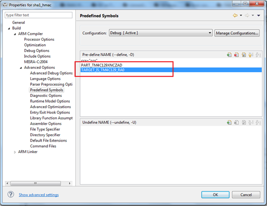
    which would mean that the defines for TM4C123 are still there in CCS. Replace TARGET_IS_TM4C123_RB1 with TARGET_IS_TM4C129_RA1 and PART_TM4C123... with PART_TM4C129...

    Please note that ... is for the exact TM4C129 part that you may be using e.g. PART_TM4C1294NCPDT is for the part on the EK-TM4C129 launchpad

    Regards

    Amit

  • Hi Amit,

    In rom.h I replaced TARGET_IS_TM4C123_RB1 with TARGET_IS_TM4C129_RA1

    In pin_map.h I replaced PART_TM4C123.. with PART_TM4C129.

    Then I rebuilt the application and ran it.

    I got the same Fault ISR.

    Thank you in advance for your help.

    Z.V

  • Hello Zvi

    You don;t have to do this in the h files but in the CCS predefine's menu

    If you can send in your project then I can quickly check and update and send it back.

    Regards

    Amit

  • Hi Amit,

    Can you do it in a new project  and send me the snapshot of the relevant window ?

    Regards,

    Z.V

  • Hello Zvi,

    Right click on the CCS Project -> Show Build Settings and then use the following snapshot to define the parameters. There should be the TARGET_IS_TM4C123_RB1 and PART_TM4C123... in the same place that you would need to replace with the two defines.

    Do make sure that the changes in rom.h and pin_map.h you have done must be undone.

    Regards

    Amit

  • Hi Amit,

    I put:

    PART_TM4C1234NCZAD

    TARGET_IS_TM4C123_RB1

    Am I right ?

    This caused several compilation problems.

    For example:

    GPIO_PB1_U1TX is undefined

    GPIO_PB5_I2C5SDA is undefined.

    Best regards,

    Z.V

  • Hello Zvi

    I would request you to send in your CCS project as a zip-attachment to the post.

    The defines that you have put is for TM4C123, while I think you are using TM4C129 device. Am I right?

    The undefined error is because you have not included driverlib/pin_map.h

    Regards

    Amit

  • Hi Amit,

    We are using TM4C1292NCPDT.

    The label on the chip is: XM4C1294NCPDT probably because it's an engineering sample.

    I will soon upload a zip with my project.

    Best regards,

    Z.V

  • Thank you Z.V

  • 3201.boot.zip

    Hello,

    Attached zip with all the project.

    Regards,

    Z.V

  • Hello Zvi,

    Why is the following line commented in Mcu.c?

        //ROM_SysCtlPeripheralEnable(SYSCTL_PERIPH_GPIOA);

    You need to enable the module. I un-commented the line and it passed the faulting location.

    Regards

    Amit

  • Hi Amit,

    I uncommented this line and currently I do not get the Fault ISR.

    But now, I2C5 hangs when trying to send a message (to a temp. sensor).

    We ran the same code on another circuit and it works fine.

    It seems we have a production problem.

    Your help is highly appreciated !

    Best regards,

    Z.V

  • Hello Zvi,

    Could it be an external Slave issue as you mentioned that on another board it works fine?

    Regards

    Amit