


Hello,
I am using a GPTM in PWM mode to control a stepper motor driver. The width of each pulse should be the same, but frequency of the pulse train should ramp up and then down, to create a trapezoidal velocity profile for the motor. The new timer period is calculated and applied to the timer in an "acceleration" interrupt that is triggered by the rising edge of the timer's CCP signal. I have tested this code a fair amount and found that it works perfectly, unless the starting frequency of the pulse train is too low.
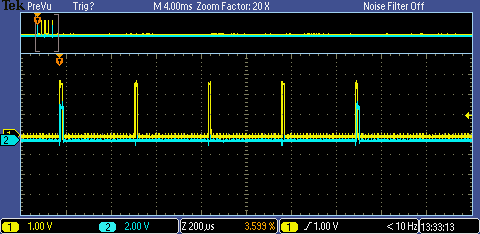
This picture shows the expected operation. Channel 1 (Yellow) is the pulse train generated by the GPTM. Channel 2 (blue) is a GPIO pin that is set high upon entry to the acceleration ISR and cleared upon exit from the ISR. The acceleration interrupt is (intentionally) disabled for the 3 pulses in the middle, because the middle portion of the move is expected to be at a constant velocity.
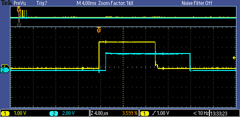
Here is a close-up of a pulse with acceleration enabled:
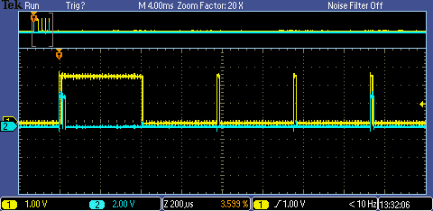
When the starting frequency of the pulsetrain is below a certain threshold, the following glitch happens:
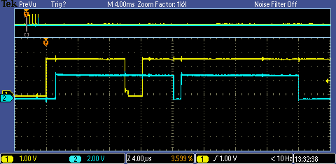
Here is a close-up of the glitch:
Here is the initial configuration of the GPTM:
	MAP_TimerConfigure(MOTOR_A_PWM_TIMER_BASE, TIMER_CFG_SPLIT_PAIR | TIMER_CFG_A_PWM);
	MAP_TimerControlLevel(MOTOR_A_PWM_TIMER_BASE, TIMER_A, false);
	MAP_TimerControlEvent(MOTOR_A_PWM_TIMER_BASE, TIMER_A, TIMER_EVENT_POS_EDGE);
	TimerUpdateMode(MOTOR_A_PWM_TIMER_BASE, TIMER_A,
			TIMER_UP_LOAD_TIMEOUT | TIMER_UP_MATCH_TIMEOUT);
	TimerIntRegister(MOTOR_A_PWM_TIMER_BASE, TIMER_A, motor_A_accel_ISR);
	MAP_TimerIntEnable(MOTOR_A_PWM_TIMER_BASE, TIMER_CAPA_EVENT);
Here is the function that sets a new frequency for the GPTM:
static void pwm_period_set(uint32_t timer_base, tcount_t period)
{
	tcount_t match_val = period - STEP_PULSE_COUNTS;

	// Set 'Load' value
	HWREG(timer_base + TIMER_O_TAILR) = (uint16_t)(period & 0xFFFF);
	HWREG(timer_base + TIMER_O_TAPR) = (uint8_t)((period >> 16) & 0xFF);

	// Set 'Match' value
	HWREG(timer_base + TIMER_O_TAMATCHR) = (uint16_t)(match_val & 0xFFFF);
	HWREG(timer_base + TIMER_O_TAPMR) = (uint8_t)((match_val >> 16) & 0xFF);
}
I wrote some code to capture the 'period', 'match_val', and TAR register at the end of each invocation of the function 'pwm_period_set'. Examining the data, I found that the glitch only occurs if TAR is greater than 'period' (by more than a few counts) at the end of the 'pwm_period_set' function. Here are the two data points that show this threshold frequency:
Issue appears here:
period = 29897
match = 29097
TAR = 29992
Issue doesn't appear here:
period = 28848
match = 28048
TAR = 28852
Note that this issue never occurs when the GPTM frequency is decreasing (deceleration), only when the frequency is increasing. From this I conclude that (in PWM mode) it is not safe to set a new GPTM period that is less than the old GPTM period IF the current TAR value is greater than the old GPTM period. What exactly is going on?
NOTE: I am using a TM4C123GH6PM, silicon rev. 7, with TivaWare 2.1.2.111.


