This thread has been locked.

If you have a related question, please click the "Ask a related question" button in the top right corner. The newly created question will be automatically linked to this question.

EK-TM4C1294XL: Co-Exist of two apps in Flash. 1st app selects which of the two runs.

Part Number: EK-TM4C1294XL
Other Parts Discussed in Thread: TM4C1294NCPDT, , ENERGIA

Hello Amit

I need to have 2 programs to co-exist in flash. The 1st located at the space of  the first 32 KB, (0x0000.0000 - 0x0000.7FFF), while the 2nd to use the address space above it starting at 0x0000.8000.

I want to have these programs EPPROM driven in the sense that after a POR or a simple reset occurs and the 1st app starts executing at 0x0000.0000, after it reads a specific position at EEPROM and finds it

let's say a 0xFF, then continue running but if find  a 0x00 to exit and hand control to the second app at 0x0000.8000. The 1st program will be a flash bootloader kind of application and the 2nd a usual flash app.

How can I tell to my 1st app to stop running and send program pointer to the 0x0000.8000 address so the 2nd app will be start executing?

Can this be done just by a direct manipulation of the program pointer and one or two registers, or am I obliged to use only the BOOTCFG register settings?. And if this even so, is one obliged to also use a pin

for driving the selection? 

The fundamental need is to perform remote bootloadings without the need of a presence of  one guy who will press a button to drive a pin while a POR occurs, so to start a bootloading.

Thank you,

John

  • Hi John,

    Not sure if what you are looking for is something like ((void (*)(void))theFixedAddress)() to jump to 0x0000.8000 if the EEPROM reading shows 0x00. BTW, Amit has additional responsibilities that his presence in TM4C forum will be less frequent. If I cannot answer your question I will seek help from others including Amit. Thanks.
  • Hello Charles and thank you for your answer.

    I was chating with Amit on similar issues weeks ago and thought he's still around.

    Your help is also exceptional in  the forum and I thank you for that.

    O.K., what I want to do is to bypass the need for a button push during processor's 

    startup through which the processor understands, by reading the bootcfg register's bits, 

    if it is a bootloading that follows or needs to jump elsewhere in flash and directly

    start running my application.

    I have lightly modified emac/bl_emac c modules so to read an EEPROM location and according

    to the value found, either wait in a loop for receiving new flash application image, or

    jump to 0x0000.8000 and start running the application image if one is already there. My bootloading

    application is the first one that I load into my TM4C129NCPDT board just like I would do

    with any other flash app. The very 1st time my app reads the predefined EEPROM location of

    the board, that just came from the manufacturer, finds it to be 0xff and so enters into the

    ethernet update procedure and starts receiving the my main application's image bin-packets

    which are served by a remote TFTP server like LM Flash Programmer, or other. After it finishes,

    by seeing that last packet contains lots of empty bytes, exits update routine, writes a 0x00

    to that "driver" EEPROM location and then performs a POR boot via a watchdog0 expiration

    (SYSCTL_ONRST_WDOG0_POR). Now the app sees a 0x00 at that EEPROM location and you 

    say Charles that by just using the ((void (*)(void))0x0000.8000)() in my code the processor will go 

    and start running my main application from that address? Is this fully confirmed? Doesn't this imply 

    that by that mean/way I can have let's say 3 different small apps loaded in flash in different address

    spaces, loaded by the same 1st bootloading app, (playing with the value of the "driver" EEPROM location)

    and then according to external conditions have these apps to jump from one to the other on demand, just

    by using this ((void (*)(void))0x0000.?000)() command? Please Charles verify if this is so. Can you

    also give to me some leads where to find more detailed info on this command regarding the

    TM4C129xxxxx processors. 

    Thank you very much. 

    John


  • Hi John,

    I think this is more a C language way of expressing pointer to function.

    The (void (*)(void) is a type of function pointer taking no argument and returning no value.
    The ((void (*)(void))0x00008000) is to type cast the address (0x00008000) to the function pointer.
    The ((void (*)(void))0x00008000)() is to execute the cast value as a function.

    Please give a try. I will suggest to start with just one application image before supporting multiples.
  • Hi Charles and thank you very much for the prompt answering.
    I'm aware of this cryptic pointer/cast/function expression of C, swupdate.c uses this anyway, but doesn't its use relates with some registers
    manipulation that one should have in mind? I'll go with its use according to your directions, just with one image and I'll let you know tomorrow on the results. Again, thank you very much......
    John
  • Hi John,
    I think your approach to having multiple applications in the flash and using the EEPROM to select between them is a good one. If I follow the thread properly, you are concerned about how to get each application to be independent of the configuration done by another application or the bootloader. One approach would be to have each application do its own initialization and then switch to another application by programming the EEPROM and then doing a system software reset. The boot code could simply read the EEPROM. If the value is 0xFFFFFFFF, it starts the bootcode. If the value is a valid flash location, it jumps to that location. If application 1 is finished and wants to transfer to application 2, it just programs the address of application 2 into the EEPROM and issues a software reset. All of the peripherals are back to the reset state so application 2 runs as though it were the only application in the device. Is this what you are trying to do?
  • Hello Bob AND thank you for your accurate reply.
    Great! This is exactly what I want to do. That way seems that an AUTOMATON, net-bot like behavior, may be obtained. More than that, if states of each one of the apps in one TM4C1294NCPDT, before resets, are passed over a port-bus bridge to nearby similar dudes, then seems that some Turing state-machine models may be implemented in pure hardware level. Which means that some good educational benefits and/or control problems solving may follow. But my needs are of lesser importance and I just need to have the capability of a) remotely flashing new firmwares over ethernet onto our TM4C1294NCPDT based controllers, b) having 3 or 4 different apps on each board's firmware for control and monitoring cases, like alarm and automation industrial systems, where interaction profiles with our controllers may change in the field in non-deterministic time spans or sequences.
    In any case, a mean other than the internal logic & processing results of the different apps is needed so to inform the applications of our board to go and write to an EEPROM location and then reboot. For that, depending on the application running, a web/tcp server is used, a client polling a server at a remote location is used and of course an SMS and/or GPRS data channeling is used as our board also hosts a SIM800 module.
    I think that Charles' advises seem to answer to my need. But what I can't yet figure out is what happens with the SP of the processor when abandons the bootloading app and goes to an address to start running another app, one of the main apps actually.
    Something that needs to be checked on the debug windows of CCS7, if possible.
    Again, thank you very much Bob,
    All the best,
    John
  • John,

    Here's a proven solution: in your 0x00 program (aka your custom bootloader) - after of course you consider your selected program conditions - what you need to do to divert code execution is:

    	{
    		HWREG(0xE000E000 + (0xD08)) = (0x4000 & 0xFFFF);	// Update vector table offset register
    		asm(" MOVW r0, #0x4000");							// Load app vector address into SP
    		asm(" ldr     sp, [r0]");
    		asm(" ldr     r0, [r0, #4]");						// Jump to starting address + 4
    		asm(" bx      r0");
    	}
    

    This example diverts execution to 0x4000 on flash. Your main app must have been compiled for that purpose, hence the .cmd file requires some changes:

    /*
     * Settings for standard compilation
     */
    // #define	APP_BASE 0x00000000
    // #define	APP_LENG 0x00100000
    // #define	RAM_BASE 0x20000000
    // #define RAM_LENG 0x00040000
    
    /*
     * Settings for NL AutoUpdate compilation (app base is offset, app length is smaller)
     */
    #define	APP_BASE 0x00004000	// Offset to match the area of the Main Firmware
    #define	APP_LENG 0x00054000	// 336Kb
    #define	RAM_BASE 0x20000000
    #define RAM_LENG 0x00040000
    
    MEMORY
    {
        FLASH (RX) : origin = APP_BASE, length = APP_LENG
        SRAM (RWX) : origin = RAM_BASE, length = RAM_LENG
    }
    

    To debug/develop your main app, you will need to revert memory mapping to the standard configuration and run it. When you are happy with the result, recompile it to start @ 0x4000 and place it in flash.

    Regards

    Bruno

  • Hello Bruno & Good Morning.

    Thank you very much for the guidelines. If I get it straight this is a proven & well working method to achieve my goal, while

    Charles' suggestion is also another one of the same kind.  What I want to ask you is that while I'll be trying your guidelines, 

    from inside my application I also need to directly modify bits in some registers and I want to use bit-banding for that.

    Shouldn't then use  #define RAM_BASE 0x22000000 instead of  #define RAM_BASE 0x20000000 in the .cmd file?

    Thank you very much,

    John

  • John Piliounis said:
    I also need to directly modify bits in some registers

    Do you mean you need to modify other bits, not specifically related to the program execution diverting? Not sure I follow...

    John Piliounis said:
    Shouldn't then use  #define RAM_BASE 0x22000000 instead of  #define RAM_BASE 0x20000000 in the .cmd file?

    RAM_BASE definition is the address where your RAM variables will begin to be stored. We have it set at 0x20... in a TM4C129x project where I copied the example from. It is probably THE correct ram base location, but I can't open the datasheet right now.

    This is "speculation", but I believe that when we divert the execution from CustomBootloader into MainApplication, we simply overwrite whatever we need into RAM, starting from the base address, hence such address can be the same - for we no longer care about any content that was initially used by CustomBootloader. Any "data transfer" between both (configuration flags for what is worth) are stored in eeprom prior to the detour. But honestly I never had the need to investigate RAM area to check if that is all true, for things just worked as expected...

    Cheers

    Bruno

  • Hi Bruno.
    My main app is the one that needs to modify bits in the SRAM bit-band region and in the Peripherals bit-band region, not my boot app. And because due to interrupts I need to avoid Read-Update-Write operations directly manipulating whole registers at their SRAM/PERIPHERAL 0x20000000 and 0x40000000 regions. That is why I use their bit-band aliases at 0x22000000 and 0x42000000 address space. Compiler needs
    to know that because is not made for using bit-band logic and so explicit declaration of this has to be done from inside C source, like the
    directive .cmd file you mention and regards to the compilation of my main application. I'll let you know on the results. Thank you very-very much again for the very precise AND helpful directions. I really appreciate all this help from TI.
    All the best,
    John
  • Hi Charles. Using the following two routines in my bootloader, I'm trying to load an app at 65536 address: [I don't use the BOOTP routines]

    for(ui32Idx = 0x00010000; ui32Idx < 0x000FA000; ui32Idx += 0x4000)

    {

    while (ROM_FlashErase(ui32Idx))

    {

    }

    I have coded a C# TCP sending app for the bin that I want to bootload in the flash memory at address 65536. I have start a TCP server on my TM4C1294NCPDT board and its associated client successfully  receives 4096 bytes per receiving session. Then I use the following routine to write to flash:

    void write_flash(int guide)
    {
    if ( guide == 0)  // guide is the file_size%4096 & base_address = 65536, 0x10000 **** I get the file-size through an initial comm-session from the remote TCP client before sending of the bin starts.
    {
    base_address += j*4096; // j is a global counter that starts from 0

    ret_val = ROM_FlashProgram(input_buffer,  base_address,  4096);   // input_buffer is the byte buffer that I store the received 4096 bytes

    Serial.print(ret_val);
    Serial.print(" >*< 4096 bytes block transfered...........Block No. ");
    Serial.println(j+1);
    j++;
    }
    else
    {
    ret_val = ROM_FlashProgram(input_buffer,  base_address,  guide);
    Serial.print(ret_val);
    }
    }

    All seem to go well but after programming ends module DOES NOT reboot although I issue the command ROM_SysCtlReset. Does not even respond to the external reset switch. Not even 

    to the watchdog reset, although at the setup stage I issue the command ROM_SysCtlResetBehaviorSet(SYSCTL_ONRST_WDOG0_POR); The same happens when I use EK-TM4C1294XL Launchpad 

    for the tests. Then after I power up the module, it does follow the EEPROM driven routine and issues  ((void (*)(void))0x00010000)(); command. But NOTHING happens. I assume I have done huge mistake somewhere, but after two days I can't figure it out. Any help is more than welcomed. Thank you,

    John

  • Hi John,

    How did you confirm that the the device does not reset when you issue the SysCtlReset or hold the RST pin?
    What does ret_val say when you program? Was the program/erase successful? If you go to 0x10000 in the memory window do you see your binary there? In CCS memory window you can write the contents to a file on a range of addresses if you want to compare what is programmed with your original binary file.
  • Charles hello.

    I always get a 0(zero) from ret_val. I print it on the debug screen so I can see it. After programming(?) finishes, my module/board, and the EK-TM4C1294XL as well, are dead frozen.

    For reset, after programming ends, I NEVER use a pin/button. I only use either the ROM_SysCtlReset command, or the watchdog method with the POR flag

    enabled. Both methods do not seem to be engaged because chip is frozen after the last flash writing/programming command. What I exactly do is as following:

    I boot load a small app by the aid of which programming of module's MAC, IP, Subnet-Mask, Gateway and DNS( not used in my apps) into EEPROM's specific locations happen.

    Then, I load my bootloader app that reads that EEPROM locations and then successfully activates a TCP/IP server. Then I remotely or locally connect to that server, with a C# TCP/IP

    client app running on a PC, and successfully transfer the bin file to my module. I can say successfully, because ret_val is always 0 while flash is programmed. But after that module 

    gives me a dead screen, while it should have reboot. If you want I can send to you both C# client app and my bootloader's code for you to check. But later tomorrow (today for us) because 

    we have a very serious National-Holiday tomorrow and everything is frozen :-)

    Again, thank you very much for all of your help,

    John

  • Hi John,

      Are you able to connect to the target and use the memory window to view what is programmed by the bootloader starting 0x10000?

      Can you monitor the DIVSCLK?  I was wondering if the clock somehow becomes inactive. However, if you can still execute some lines of code then the clock should be active. Can you please confirm this? Unless the clock is inactive, I can't understand why the WD reset does not kick in? Can you also try an experiment to cause a WD reset before you start bootloader programming?

      Sorry, I'm still on vacation since Wednesday. I only have the iPAD and can't really run any code. 


  • Dear Charles, hello and thank you very much for your reply. Clock is operating at all times. It seems I had a mistake in the memory metrics and accidentally I was overwriting areas of the bootloading app area. Maybe that was the reason for ending up with a frozen board. Now, watchdog operates as it should but after the first 41 parts that I write in the flash getting 0s, I start getting -1s for the rest. I'm on this for a couple of days now and I don't yet have a clear picture. My scenario goes like this:

    1) I use a small app in the beginning that I load onto my board through the JTAG port,  through which I mark a specific EEPROM  location to be '1' and also I write IP,SUBNET, GATEWAY, and MAC to some other locations. (MAC is also burned in the USERx registers through LM Flash Programmer / commit  at this 1st stage)

    2) I then load my bootloader app, again through the JTAG port, which reads all the parameters from EEPROM locations and since the specific location is a '1' starts a TCP server waiting for connections. At this point watchdog has been already initiated and properly fed and also serial-debug port is also enabled for getting various debug messages I have code in the boot-app. 

    3) Now, I successfully remotely connect onto my board through a remote TCP C#-coded client running on a PC and I first send the file size of the bin app-file that I want to load onto my board. The boot-app on the board gets this info and creates two vars: parts = file_size/4096, last_part = file_size%4096 (the remaining bytes). Then sends a tcp message to the remote PC app to send the 1st package (part) of 4096 bytes which I read in a byte array. When 4096 bytes have been read, my app fills up a -> uint32_t flash_input_buffer[1024] <- using the -> byte input_buffer[4096] <- which has just been filled up. This is done as following: (the described procedure repeats 'parts' times.)

    for (j = 0; j < 1024; j++)
    {

       flash_input_buffer[l] = ( input_buffer[4*j + 0] << 24 | input_buffer[4*j + 1] << 16 | input_buffer[4*j + 2] << 8 | input_buffer[4*j + 3] );

    My app then immediately goes and flashes the data as following:  ret_val = ROM_FlashProgram(flash_input_buffer, base_address, 1024);, where the base _address = 0x10000 and in every write of the 'parts' increases  by 1024 addresses as,  base_address += q*1024, where q = 0 for the 1st part and so on. 

    ///*** Note that input_buffer fills with new bytes from the remote sending tcp app in every 'parts' loop.  The remote PC app gets a tcp notification from the boot-app to start sending the next stream of 4096 or final                 bytes, AFTER every successful read and FLASH-write has happened. So all bytes are read deterministic ***///

    The last loop in the boot-app goes like, 

    for (j = 0; j < last_part/4; j++)
    {

        flash_input_buffer[l] = ( input_buffer[4*j + 0] << 24 | input_buffer[4*j + 1] << 16 | input_buffer[4*j + 2] << 8 | input_buffer[4*j + 3] );
    }

    and then again,  ret_val = ROM_FlashProgram(flash_input_buffer, base_address, last_part/4),  where base_address has been prepared in the last 'parts' loop before.

    After part 41, or 42, for a 226884 bytes long main app I start getting -1s. Does it seem that I make a logical or metrics mistake somewhere?  (Flash erase has been done correctly before any new flash programming and for being sure that my flash-erase doesn't mess things up, I also used LM Flash Programmers flash-erase utility option but nothing changed in getting -1s)

  • Hi John,

      I just wanted to make sure if you have any write protection on the flash beyond part 41 or 42. Can you please also monitor the base_address to see if it increments properly after part 41 or 42? I assume your application code to be programmed is much greater than 42 parts, correct? I assume the flash_input_buffer contains correct data (non -1s) with q>=42, right?

      One thing not very clear to me is that you said the first 41 parts are getting zeros. Are you downloading a binary which is all zeros as an experiment or proper binary image is programmed successfully at the for the first 41 parts? 


  • Charles, hello again.

    O.K. I traced the error.  If you look at the code I send above, what I'm doing in order to increase the memory address 1024 locations at a time in each new write is foolish by mistake. I write:

    ***************** My app then immediately goes and flashes the data as following:  ret_val = ROM_FlashProgram(flash_input_buffer, base_address, 1024);, where the base _address = 0x10000 and in every write of the 'parts' increases  by 1024 addresses as,  base_address += q*1024, where q = 0 for the 1st part and so on. ****************

    base_address should increase as: base_address += 1024 AND NOT as base_address += q*1024 !!!  Yes, as you say, my app is 55 chunks of 4096 bytes each and 1604 bytes at the end. Now everything is received as it should and everything is written in flash as it should and watchdog reboots as it should. Before each flash-write I print the address of the current programming location and all Address-Values are indeed 1024 locations apart. I always get a 0 ret_val in each FlashProgram command AND ALSO, before I FashProgram each steam of the received data I send them over another tcp client to another PC and rebuild the original bin there. By the time all flash programming has finished I compare the initial and the final bins, bye-to-byte and are always found IDENTICAL. So I'm sure that what has been written in flash reflects to the original bin.

    AND NOW the last problem. After the watchdog boots the IoT module, the boot app now finds EEPROM specific location written as '0' (the last thing my boot-app does before watchdog reboot). So directly issues the command ((void (*)(void))0x00010000)() but nothing happens and the debug screen remains blank for ever. Even if I power reboot the module the main-app does not start. Only a blank debug screen is what I get. Should this command needs and others to be issued before it?

    As always, any help is more than welcomed. Thank you very much, John.

  • Hello Bruno. I would like to ask you to verify that if I need to use the 0x00010000 address as the starting address of my application in flash then I would need to modify your ASM code as following:
    {
    HWREG(0xE000E000 + (0xD08)) = (0x10000 & 0xFFFFF); // Update vector table offset register
    asm(" MOVW r0, #0x0000");
    asm(" MOVT r0, #0x0001");
    asm(" ldr sp, [r0]");                         // Load app vector address into SP
    asm(" ldr r0, [r0, #4]"); // Jump to starting address + 4
    asm(" bx r0");
    }
    or instead of the two MOVW, MOVT commands could use the ldr r0, =0x00010000 Is any, or both, of the previous options o.k. to use?

    Also, if I include/put only the #define APP_BASE 0x00010000 // Offset to match the area of the Main Firmware // in my main app's definitions area, would that be O.K. with the compiler?

    Do I have to include those 3 DEFs? **********************************************
    #define APP_LENG 0x00054000 // 336Kb ////
    #define RAM_BASE 0x20000000
    #define RAM_LENG 0x00040000
    ********************************************************************************
    Thank you very much,
    John

  • Hello Charles, Bruno & all. There is gradual success, but success. The project's status is as following:

    Because, I'm not eventually sure IF the flash programming procedure that I follow succeeds in properly flashing the module, I thought of the following procedure to follow, to verify at least that both my boot-app and main-app are properly loading in flash and communicate. So what I did, is to load the boot-app with LM Flash Programmer at "Program Address Offset: 0x00000000" as usual, AND to load my main-app, again with LM Flash Programmer, at  "Program Address Offset: 0x00010000". SO NOW, having already the specific EEPROM location programmed to a '0', AFTER EACH REBOOT, my boot-app at 0x00000000 hands immediately the control to the main-app at 0x00010000. BIG SUCCESS, which I owe to you guys, and thank you for all of your help in doing that. Some very useful data now for all the folks in our community in the forum:

    a) My boot-app uses the following code, as suggested by Bruno and Charles, slightly modified by me to go beyond the 2-bytes address limit :

        Method 1: (This code run from inside the boot-app at the point we decide to hand control to our main-app which is located, in my case, at  0x000100000. Boot-app is located at 0x00000000 )

    HWREG(0xE000E000 + (0xD08)) = (0x10000 & 0xFFFFF);  // Update vector table offset register
    asm(" MOVW r0, #0x0000");   // Low Bytes of the 32-bit address  
    asm(" MOVT r0, #0x0001");    // High Bytes of the 32-bit address. Look at the ASM table of commands of Cortex-M3, M4
    asm(" ldr sp, [r0]");                   // Load app vector address into SP
    asm(" ldr r0, [r0, #4]");             // Jump to starting address + 4
    asm(" bx r0");                            //  After this command your module will start the main-app

        Method 2: (Again, this code run from ......)

    (*((void (*)(void))(*(uint32_t *)0x00010004)))();

    b)  As Bruno suggested, for the main-app to be able to successfully be relocated in the desired address, (in my case 0x000100000), we need to FOLLOW TWO IMPORTANT steps:

    Step 1: Inside the main body of the source code of our main-app, we need to make the following definitions, so the compiler will have the knowledge where to put some addressing vectors during compilation.

    /// ****************************** Directives to Compiler for Upper Flash Relocation of our main-app's code
    #define APP_BASE 0x00010000
    #define APP_LENG 0x00060000   // the length must be larger that the app's length.
    #define RAM_BASE 0x20000000
    #define RAM_LENG 0x00040000
    /// ******************************

    Step 2: Linker also, NEEDS to know how to handle the binary addressing space for the particular MEMORY schema of our ARM processor. In our case the snowflake family. For that to happen, we need to make a minor modification to the LINKER's guiding file which has the extension .ld / .lds We can easily locate this file with a search in our dev's environment directories. 

    For CCS7 it is at ***\ccsv7\ccs_base\arm\include\tm4c1294ncpdt.lds and for ENERGIA is at *****\energia-0101E0017\hardware\lm4f\cores\lm4f\lm4fcpp_snowflake.ld.

    The file contains a source block like below:

    MEMORY
    {
    flash (rx) : ORIGIN = 0x00000000, LENGTH = 0x00100000
    ram (rwx) : ORIGIN = 0x20000000, LENGTH = 0x00040000
    }

    There we need to change  ONLY the flash(rx): ORIGIN = 0x00000000 to  ORIGIN = 0x00010000 and LENGTH = 0x00100000 we may leave it as is or have it as LENGTH = 0x00060000

    BEWARE, we need to revert to the original values for our other apps that we need to start normally at 0x00000000

    *************************************** So far so good.

    But Charles/Bruno, I can't yet figure our why the bin image of my main-app is not written in flash memory with the method I described in my post yesterday. What I did today, is that I used LM Flash Programmer's UTILITY, 'Upload Flash Contents to a .bin file' and I read all contents from 0x000100000 to 0x000600000 into a test.bin file which I then edit with a HEX editor. Unfortunately, ALL SPACE WAS EMPTY!!!! Means that although I was getting a 0 as the ret_val = ROM_FlashProgram(....,  ....,  .....) nothing was written in the flash. That I can not explain. Please advice what I'm doing wrong and what would be a proper method to write to flash.

    Thank you all very much,

    John

  • Hello Charles, Bruno & all. There is gradual success, but success. The project's status is as following:

    Because, I'm not eventually sure IF the flash programming procedure that I follow succeeds in properly flashing the module, I thought of the following procedure to follow, to verify at least that both my boot-app and main-app are properly loading in flash and communicate. So what I did, is to load the boot-app with LM Flash Programmer at "Program Address Offset: 0x00000000" as usual, AND to load my main-app, again with LM Flash Programmer, at "Program Address Offset: 0x00010000". SO NOW, having already the specific EEPROM location programmed to a '0', AFTER EACH REBOOT, my boot-app at 0x00000000 hands immediately the control to the main-app at 0x00010000. BIG SUCCESS, which I owe to you guys, and thank you for all of your help in doing that. Some very useful data now for all the folks in our community in the forum:

    a) My boot-app uses the following code, as suggested by Bruno and Charles, slightly modified by me to go beyond the 2-bytes address limit :

    Method 1: (This code run from inside the boot-app at the point we decide to hand control to our main-app which is located, in my case, at 0x000100000. Boot-app is located at 0x00000000 )

    HWREG(0xE000E000 + (0xD08)) = (0x10000 & 0xFFFFF); // Update vector table offset register
    asm(" MOVW r0, #0x0000"); // Low Bytes of the 32-bit address
    asm(" MOVT r0, #0x0001"); // High Bytes of the 32-bit address. Look at the ASM table of commands of Cortex-M3, M4
    asm(" ldr sp, [r0]"); // Load app vector address into SP
    asm(" ldr r0, [r0, #4]"); // Jump to starting address + 4
    asm(" bx r0"); // After this command your module will start the main-app

    Method 2: (Again, this code run from ......)

    (*((void (*)(void))(*(uint32_t *)0x00010004)))();

    b) As Bruno suggested, for the main-app to be able to successfully be relocated in the desired address, (in my case 0x000100000), we need to FOLLOW TWO IMPORTANT steps:

    Step 1: Inside the main body of the source code of our main-app, we need to make the following definitions, so the compiler will have the knowledge where to put some addressing vectors during compilation.

    /// ****************************** Directives to Compiler for Upper Flash Relocation of our main-app's code
    #define APP_BASE 0x00010000
    #define APP_LENG 0x00060000 // the length must be larger that the app's length.
    #define RAM_BASE 0x20000000
    #define RAM_LENG 0x00040000
    /// ******************************

    Step 2: Linker also, NEEDS to know how to handle the binary addressing space for the particular MEMORY schema of our ARM processor. In our case the snowflake family. For that to happen, we need to make a minor modification to the LINKER's guiding file which has the extension .ld / .lds We can easily locate this file with a search in our dev's environment directories.

    For CCS7 it is at ***\ccsv7\ccs_base\arm\include\tm4c1294ncpdt.lds and for ENERGIA is at *****\energia-0101E0017\hardware\lm4f\cores\lm4f\lm4fcpp_snowflake.ld.

    The file contains a source block like below:

    MEMORY
    {
    flash (rx) : ORIGIN = 0x00000000, LENGTH = 0x00100000
    ram (rwx) : ORIGIN = 0x20000000, LENGTH = 0x00040000
    }

    There we need to change ONLY the flash(rx): ORIGIN = 0x00000000 to ORIGIN = 0x00010000 and LENGTH = 0x00100000 we may leave it as is or have it as LENGTH = 0x00060000

    BEWARE, we need to revert to the original values for our other apps that we need to start normally at 0x00000000

    *************************************** So far so good.

    But Charles/Bruno, I can't yet figure our why the bin image of my main-app is not written in flash memory with the method I described in my post yesterday. What I did today, is that I used LM Flash Programmer's UTILITY, 'Upload Flash Contents to a .bin file' and I read all contents from 0x000100000 to 0x000600000 into a test.bin file which I then edit with a HEX editor. Unfortunately, ALL SPACE WAS EMPTY!!!! Means that although I was getting a 0 as the ret_val = ROM_FlashProgram(...., ...., .....) nothing was written in the flash. That I can not explain. Please advice what I'm doing wrong and what would be a proper method to write to flash.

    Thank you all very much,

    John
  • John,

    My apologies for not being able to analyze this more deeply, as I'm under a myriad of technical challenges at the moment which are kind of draining whatever's left in there...

    But a couple of ideas NOT having read your post properly:

    - Are you by any change rewriting other app's memory regions when you upload another firmware? If you are using any PC flasher, the tendency is to write the whole flash again unless you carefully choose the destination.

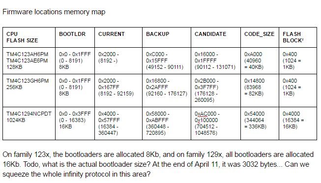
    What we do for this bootloader/updater story is to use a library inside the "main" application - so it receives update packages and stores them in the proper local of flash without touching the running app; only on next bootloader, our bootloader manouvers the blocks. As a matter of fact, our "actual" application always runs in the same location, and the old backup or the future "candidate" are stored somewhere temporarily. Still, there is a permanent custom bootloader app (which never changes), from 0x0000 to about 8K.

    Actually, looking for the real table:

    Later, we needed firmware that are longer than 1/3 of the available memory, so we have a bit of a different arrangement saving the backup and candidate in an external memory, but that's not yet into production products.

    Regards

    Bruno

  • Hello John

    As Bruno indicated the size of the Flash is 1MB on the TM4C129x device family. So you main application cannot reside at the end of flash. It should be at the page boundary after the boot image.