This thread has been locked.

If you have a related question, please click the "Ask a related question" button in the top right corner. The newly created question will be automatically linked to this question.

TM4C129ENCPDT: Changing from crystal to external oscillator and I2C

Part Number: TM4C129ENCPDT

Hello.

Due to some HW requirements, we had to change from using a 25MHz crystal to a 25MHz external oscillator (which comes from a 50MHz divided by 2) on the OSC0 pin. The SW hasn't changed at all (we were using Tivaware 2.1.0.12573 version).

Is it necessary to change our call to the SysCtlClockFreqSet function? Right now is:

g_ui32SysClock = MAP_SysCtlClockFreqSet((SYSCTL_XTAL_25MHZ | SYSCTL_OSC_MAIN | SYSCTL_USE_PLL | SYSCTL_CFG_VCO_480), 120000000);

On the other hand, we are seeing some odd behaviour on the I2C ports (SDA and SCL and out of time).

Is there any change in the I2C clocking because of the external oscillator? The I2CMasterInitExpClk call, remains the same.

Thank you

  • PAk said:
    Is it necessary to change our call to the SysCtlClockFreqSet function?

    The TM4C129ENCPDT datasheet has the following description for the PWRDN field in the Main Oscillator Control (MOSCCTL) register:

    From looking at the source of SysCtlClockFreqSet in TivaWare_C_Series-2.1.4.178 the SYSCTL_MOSCCTL_PWRDN bit is always cleared.

    Therefore, after the existing SysCtlClockFreqSet I think you might need to add:

        SysCtlMOSCConfigSet (SYSCTL_MOSC_PWR_DIS);

    Note that I haven't tested this, and not sure if setting the PWRDN bit after SysCtlClockFreqSet has attempted to synchronize the PLL will generate a valid clock. There appears to be an omission that the SysCtlClockFreqSet () doesn't have an option to allow a single-ended input to be specified for the main oscillator.

    You might need to create a modified SysCtlClockFreqSet () which doesn't clear the PWRDN bit before attempting to synchronize the PLL.

    PAk said:
    On the other hand, we are seeing some odd behaviour on the I2C ports (SDA and SCL and out of time).

    My guess is that the hardware detected a failure of the non-existent crystal and so the system frequency hasn't been set correctly.

    Did the SysCtlClockFreqSet function return a value of zero indicating failure?

    Edit: Corrected SYSCTL_MOSC_SESRC to SYSCTL_MOSC_PWR_DIS.

  • Chester Gillon said:

    PAk
    Is it necessary to change our call to the SysCtlClockFreqSet function?

    The TM4C129ENCPDTdatasheet has the following description for the PWRDN field in the Main Oscillator Control (MOSCCTL) register:

    From looking at the source of SysCtlClockFreqSet in TivaWare_C_Series-2.1.4.178 the SYSCTL_MOSCCTL_PWRDN bit is always cleared.

    Therefore, after the existing SysCtlClockFreqSet I think you might need to add:

        SysCtlMOSCConfigSet (SYSCTL_MOSC_PWR_DIS);

    Note that I haven't tested this, and not sure if setting the PWRDN bit after SysCtlClockFreqSet has attempted to synchronize the PLL will generate a valid clock. There appears to be an omission that the SysCtlClockFreqSet () doesn't have an option to allow a single-ended input to be specified for the main oscillator.

    You might need to create a modified SysCtlClockFreqSet () which doesn't clear the PWRDN bit before attempting to synchronize the PLL.

    PAk
    On the other hand, we are seeing some odd behaviour on the I2C ports (SDA and SCL and out of time).

    My guess is that the hardware detected a failure of the non-existent crystal and so the system frequency hasn't been set correctly.

    Did the SysCtlClockFreqSet function return a value of zero indicating failure?

    Edit: Corrected SYSCTL_MOSC_SESRC to SYSCTL_MOSC_PWR_DIS.

    Thank you Chester for your quick answer.

    However, calling: 

     SysCtlMOSCConfigSet (SYSCTL_MOSC_PWR_DIS);

    after SysCtlClockFreqSet did not work (at least I had the same problem with I2C). The communications via UART and Ethernet work fine, program seems to run but the I2C is not working properly.

    The return call of SysCtlClockFreqSet shows g_ui32SysClock=120000000. I think it is possible to use as the system clock even with an external oscillator, right?

    Thanks again

  • PAk said:
    The communications via UART and Ethernet work fine, program seems to run but the I2C is not working properly.

    Different peripherals have different clock sources. From looking at the datasheet:

    a) The EMAC (Ethernet) uses the main oscillator, which requires a 25MHz cyrstal.

    b) The UART can use either the System Clock or Global Alternate Clock for the baud rate clock source. [Where the Global Alternate Clock defaults to the trimmed 16 MHz PIOSC]

    c) The I2C uses the System Clock as the clock source.

    Therefore, if the System Clock is set to the wrong frequency the I2C peripheral will be affected, but the Ethernet and UART (using the Global Alternate Clock) can continue to operate correctly.

    I have been playing with code which validates the actual System Clock frequency has been set to the correct value by SysCtlClockFreqSet(), by running two timers clocked off the PIOSC (fixed nominal 16 MHz) and the System Clock. The code is:

    /*
     * main.c
     */
    
    #include <stdbool.h>
    #include <stdint.h>
    #include <stdio.h>
    
    #include <inc/hw_memmap.h>
    #include <driverlib/sysctl.h>
    #include <driverlib/timer.h>
    
    /** The device is test with the clock frequency set to the maximum allowed for TM4C129 devices */
    #define CLOCK_FREQUENCY_HZ 120000000
    
    /** The trimmed internal PIOSC frequency */
    #define PIOSC_FREQUENCY_HZ 16000000
    
    /**
     * @brief Initialise the system clock, and perform a sanity check that the expected frequency has been set
     */
    static void initialise_clock (void)
    {
        uint32_t reported_frequency;
        uint32_t piosc_start_ticks, piosc_stop_ticks;
        uint32_t sys_clock_start_ticks, sys_clock_stop_ticks;
    
        reported_frequency = SysCtlClockFreqSet ((SYSCTL_XTAL_25MHZ | SYSCTL_OSC_MAIN | SYSCTL_USE_PLL | SYSCTL_CFG_VCO_480),
                                                 CLOCK_FREQUENCY_HZ);
    
        SysCtlPeripheralDisable (SYSCTL_PERIPH_TIMER0);
        SysCtlPeripheralDisable (SYSCTL_PERIPH_TIMER1);
        SysCtlPeripheralReset (SYSCTL_PERIPH_TIMER0);
        SysCtlPeripheralReset (SYSCTL_PERIPH_TIMER1);
        SysCtlPeripheralEnable (SYSCTL_PERIPH_TIMER0);
        SysCtlPeripheralEnable (SYSCTL_PERIPH_TIMER1);
        while (!SysCtlPeripheralReady (SYSCTL_PERIPH_TIMER0) || !SysCtlPeripheralReady (SYSCTL_PERIPH_TIMER1))
        {
        }
    
        /* Set timer0 to a 32-bit periodic up counter driven from the system clock */
        TimerClockSourceSet (TIMER0_BASE, TIMER_CLOCK_SYSTEM);
        TimerConfigure (TIMER0_BASE, TIMER_CFG_PERIODIC_UP);
        TimerLoadSet (TIMER0_BASE, TIMER_A, 0xffffffff);
        TimerEnable (TIMER0_BASE, TIMER_A);
    
        /* Set timer1 to a 32-bit periodic up counter driven from the PIOSC */
        TimerClockSourceSet (TIMER1_BASE, TIMER_CLOCK_PIOSC);
        TimerConfigure (TIMER1_BASE, TIMER_CFG_PERIODIC_UP);
        TimerLoadSet (TIMER1_BASE, TIMER_A, 0xffffffff);
        TimerEnable (TIMER1_BASE, TIMER_A);
    
        /* Wait for what should be one second, based upon the timer driven from the PIOSC */
        piosc_start_ticks = TimerValueGet (TIMER1_BASE, TIMER_A);
        sys_clock_start_ticks = TimerValueGet (TIMER0_BASE, TIMER_A);
        do
        {
            piosc_stop_ticks = TimerValueGet (TIMER1_BASE, TIMER_A);
            sys_clock_stop_ticks = TimerValueGet (TIMER0_BASE, TIMER_A);
        } while ((piosc_stop_ticks - piosc_start_ticks) < PIOSC_FREQUENCY_HZ);
    
        const uint32_t sys_clock_ticks_per_sec = sys_clock_stop_ticks - sys_clock_start_ticks;
        printf ("Requested clock frequency : %u Hz\n", CLOCK_FREQUENCY_HZ);
        printf ("Clock frequency reported by SysCtlClockFreqSet() : %u Hz\n", reported_frequency);
        printf ("Measured clock frequency = %u Hz\n", sys_clock_ticks_per_sec);
    }
    
    int main(void)
    {
        initialise_clock ();
    
        return 0;
    }

    When run on a launchpad with a 25 MHz crystal the results were:

    Requested clock frequency : 120000000 Hz
    Clock frequency reported by SysCtlClockFreqSet() : 120000000 Hz
    Measured clock frequency = 119011383 Hz

    There is an apparent 0.8% error, but that is probably down to the the PIOSC being used as the timing reference.

    If you run the above code on your hardware what measured clock frequency is reported?

  • While the effort & detail displayed here by Chester is exemplary - would it not prove far faster/easier to, "output and measure a "frequency divided" (smallest divisor possible) replica of the System Clock - via a Timer - forced into PWM Mode?"    (this assumes that this MCU (129x) may employ the System Clock as input clock source for the Timer.)

    Absent poster's report as well - his measurement of the SCL frequency - both "prior to" and "post" the change of MCU's clock source.    

    And - as always - has this effort been launched for a "single board" - as opposed to a (far more meaningful) "several board" occurrence?     "Anything is possible/suspect" w/"single board" - that same effect noted (and repeated) across multiple boards/MCUs - substantially raises the likelihood of a (real) MCU issue.    (not a board build/assembly error - seen just once!)

  • Thank you Chester.

    After running the program twice I get this results with the JTAG probe:

    [CORTEX_M4_0] Requested clock frequency : 120000000 Hz
    Clock frequency reported by SysCtlClockFreqSet() : 120000000 Hz
    Measured clock frequency = 119467097 Hz

    Requested clock frequency : 120000000 Hz
    Clock frequency reported by SysCtlClockFreqSet() : 120000000 Hz
    Measured clock frequency = 119507513 Hz

    So 99.5%.....even I didn't use the SysCtlMOSCConfigSet (SYSCTL_MOSC_PWR_DIS); call.

  • PAk said:
    So 99.5%

    OK, the System Clock frequency as measured by a timer is correct.

    Can you show how the 2C Master Timer Period is set, and also give more details on the I2C timing problem?

    E.g. show a scope capture for the working (25MHz crystal) and non-working (25MHz single ended input on OSC0) cases.

    Also, using the CCS debugger can you check the value of the  I2C Master Timer Period (I2CMTPR) register for the working and non-working cases.

  • Thank you Chester.

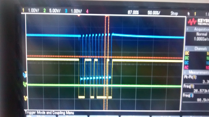
    The problem with I2C, is that with the same code, the I2C signals look like this:

    And on the crystal board, look like this:

    It seems to be a delay between them (on the same pins).

  • Your presentation of those, "Comparative Scope Traces" - as my initial post suggested - has enabled, "Real Analysis."     While you initially noted, "odd behavior" - the single trace suggests, "NO CHANCE" of I2C working - at all!

    Top trace reveals a complete "break" between SCL & SDA!    Note that the scope records SCL as 128.9KHz.     This almost surely signals a significant MCU "set-up" issue - or the inability of this MCU to accept your changed input source.    Returning to your report of "odd behavior" - if it proves true that (some) I2C transfers succeed - then your SCL to SDA timing "MUST" be varying - which is extremely hard to grasp.    Under your new operation - have you EVER known an I2C transfer to succeed?     That is far beyond "odd behavior" - and that clarity (has a new transfer EVER worked) is required & requested.

    Bottom trace reveals an expected (proper) display of SCL clocking SDA. And SCL (appears) to be 98.5KHz - much closer to 100KHz standard.

    Such is FAR BEYOND a "delay" - the top trace reports an unusable (and illegal) I2C output.    The I2C clock must be well synchronized to the I2C data - clearly yours fails to "come close."

    To ease such comparisons - it would prove useful to transmit the identical data - and to attempt to fit the signals so that they "fill" as much of the scope as possible. (suspect that widening the time-base one click would achieve better fill - enabling easier signal edge reading)

  • cb1_mobile said:

    Your presentation of those, "Comparative Scope Traces" - as my initial post suggested - has enabled, "Real Analysis."     While you initially noted, "odd behavior" - the single trace suggests, "NO CHANCE" of I2C working - at all!

    Top trace reveals a complete "break" between SCL & SDA!    Note that the scope records SCL as 128.9KHz.     This almost surely signals a significant MCU "set-up" issue - or the inability of this MCU to accept your changed input source.    Returning to your report of "odd behavior" - if it proves true that (some) I2C transfers succeed - then your SCL to SDA timing "MUST" be varying - which is extremely hard to grasp.    Under your new operation - have you EVER known an I2C transfer to succeed?     That is far beyond "odd behavior" - and that clarity (has a new transfer EVER worked) is required & requested.

    Bottom trace reveals an expected (proper) display of SCL clocking SDA. And SCL (appears) to be 98.5KHz - much closer to 100KHz standard.

    Such is FAR BEYOND a "delay" - the top trace reports an unusable (and illegal) I2C output.    The I2C clock must be well synchronized to the I2C data - clearly yours fails to "come close."

    To ease such comparisons - it would prove useful to transmit the identical data - and to attempt to fit the signals so that they "fill" as much of the scope as possible. (suspect that widening the time-base one click would achieve better fill - enabling easier signal edge reading)

    That is true...I also tested at 400kHz on the Oscillator board, and I am getting a 330kHz clock. I2C has never worked on this board, hopefully, the delay seems to be constant for every speed of the bus.

    Maybe there is something to configure for I2C when using an external oscillator (instead of an external crystal) that TI staff can point me.

    Best regards

  • PAk said:
    Maybe there is something to configure for I2C when using an external oscillator (instead of an external crystal)

    Indeed - although poster Chester made great effort in identifying, "Set-Up & Configuration" (potential) limitations - imposed by your use of an external oscillator.    We must note that "many/most" MCUs do accept & perform well under external oscillators - the Ethernet capability of your device (most likely) has added sensitivities to the input clock source.

    The factory is best equipped to (really/deeply) advise in such matter.    (not all "ins/outs" of the device are published - by this vendor or (similar) others)

    I know your penchant for "saving" - yet it must be noted that your (return) to the past (successful) 25MHz xtal circuit - completely avoids this (new: failing I2C) issue.

    Might you better indicate your intent in writing, "Odd I2C behavior?"     From the single (failed) waveform presented - I cannot accept that ANY i2C transfer could succeed!   (the loss of "clock to data Sync" is massive!)

    As to a "potential fix" - isn't it likely that your (new, added) oscillator forces added trace length - in the path from oscillator to MCU?    Might other high speed signals run near - and/or parallel - to the oscillator's connection track"?    And - if the oscillator was added w/out an official "pcb redesign to accommodate the oscillator" have you simply "cabled in" the oscillator's output?   The MCU's crystal input circuit "expects" 2 inputs - how have you treated the (now) empty (Osc1, I believe) input?      This detail/description is useful should your issue be EXTERNAL to the MCU - thus unknown by vendor's tech staff!

    You speak of the "divide by two" - that is ALL achieved w/in the oscillator - is that true?   (I don't believe the MCU can accept so high a frequency (50MHz) and then implement your "divide."   Again - do describe.)

    Just dawns - might you replace the existing 50MHz oscillator w/several others - from different vendors - & test/observe?     (one of the staff here recalled such an issue - although w/another's Cortex M4 - and the change of oscillator did work!)    Note that this "substitute other oscillator makes" may make most sense (only) after the other board design/implementation issues - listed here - have been revealed!

  • There is no inherent difference in using a crystal, or an external oscillator of the same frequency. However, when using an external oscillator you need to be sure there are no reflection on the OSC0 line. A reflection might be interpreted as an extra clock edge by the PLL and it would try to momentarily speed up to twice the frequency causing unpredictable results.

    As an experiment, you might try running the PLL off of the 16MHz precision internal oscillator to see if that solves the problem.
  • Found the issue...an error on manufacturing avoiding some pull up resistor, made some i2C IC in the bus had a behaviour as an UART. Probably the dealyed signal was an answer of that device (to our signal scl).

    Sorry for the mistake, thank you all for your great help.

    I hope this helps somebody in the future, for me it has clarified that is the same to use a crystal or an external oscillator. 

  • Bob Crosby said:
    There is no inherent difference in using a crystal, or an external oscillator of the same frequency

    Out of curiosity, does that mean the datasheet note about the PWRDN field in the Main Oscillator Control (MOSCCTL) register needing to be set for single-ended mode is incorrect?

  • Bob - thank you - appreciated.

    Might you advise - what is the proper treatment of "MCU's OSC1" when an oscillator - rather than an xtal - drives OSC0?     In most (past) MCUs - "OSC1" serves as output feedback to the crystal circuit - thus may be left unconnected.

    O.P.'s diagnosis proves (not) especially compelling.

  • Setting the PWRDN bit disables the unbuffered inverter that drives the crystal. That reduces power consumption and electrical emissions.  You are correct in advising the original poster that it should be set when operating in single input mode, but it was not likely the cause of an incorrect frequency.

  • Hi CB1,
    You are correct, the OSC1 should be left unconnected when OSC0 is driven by an oscillator.

    I think PAk's problem was totally unrelated to the change from crystal to oscillator. My understanding is (PAk, please correct me if I am wrong) that the original board with a crystal worked, but the modified board with the oscillator did not. The only "intentional" change was from crystal to oscillator, but there was an unintentional missing resistor that cause one of the I2C slave device to configure its I2C lines as UART lines. I think that caused a drive conflict so the TM4C could not drive the SDA line low. Looking back to the failing scenario scope shot, you see what looks like a drive conflict on SDA with the first SCL edge. When it fails to drive SDA low, the I2C kept clocking, but quit driving SDA. The second transmission is interesting in that it looks like a drive conflict on SCL and SDA is now correct. Interesting, but academic as the problem has now been resolved. (And I have no shortage of interesting problems to ponder.)
  • Especially "no shortage" of those (always well thought) "interesting problems" presented as, "Does NOT work!"     (suggesting that is "your" fault!)

    Thanks for the confirmation of "OSC1's" handling.    Poster's description of "odd I2C behavior" (when clearly there was NO I2C capability possible) and then the "suddenness" of the fix - causes my "xtal-ball" to predict, "poster's return."

  • Bob Crosby said:
    Hi CB1,
    You are correct, the OSC1 should be left unconnected when OSC0 is driven by an oscillator.

    I think PAk's problem was totally unrelated to the change from crystal to oscillator. My understanding is (PAk, please correct me if I am wrong) that the original board with a crystal worked, but the modified board with the oscillator did not. The only "intentional" change was from crystal to oscillator, but there was an unintentional missing resistor that cause one of the I2C slave device to configure its I2C lines as UART lines. I think that caused a drive conflict so the TM4C could not drive the SDA line low. Looking back to the failing scenario scope shot, you see what looks like a drive conflict on SDA with the first SCL edge. When it fails to drive SDA low, the I2C kept clocking, but quit driving SDA. The second transmission is interesting in that it looks like a drive conflict on SCL and SDA is now correct. Interesting, but academic as the problem has now been resolved. (And I have no shortage of interesting problems to ponder.)

    That is a perfect description about what has happened.

    Thak you for your time

  • That is a perfect description of what has happened.

    Thank you for your time
  • As the description is judged "perfect" - might you identify the (troublesome) I2C slave device - and the pin which "missed" the required pull-up - so that your (interesting yet unusual)  finding may be replicated.

    As firm/I are not 129x fans - I've asked a client to "duplicate your set-up" & test/report.    They too had I2C issue - which proved to be noise imposed upon the oscillator output - as I noted earlier.    Client would really appreciate your listing of those 2 simple details.     (i.e. slave device make/model & pin "missing" pull-up)      We did try to assist & would much appreciate your input...

  • Yes, a BoSCH BNOXXX IMU device.

    The behaviour repeats itself across the boards

  • Thank you - and which pin "missed" the pull-up?     Our firm has never/ever seen nor heard of a legitimate I2C Slave behaving in this manner!

  • Thank you - much appreciated... BTW - we should "PM" re: "Meta Material" as employed in "Phased Array Radar." (firm/I have latest/greatest - might accept your "first born" in trade.     (provided - of course - that he/she proves adequate in smt soldering!)

    Good - mystery solved (& most unexpected) it appears that it was NOT the absence of a pull-up resistor - but (rather) the (special) connection of the Adafruit Eval Board's "PS1" to 3V3 - which switched the Bosch device from I2C to UART.    (and the "only" means to do that)     Here - for those interested - is a true copy from the linked page:

    "You'll need to connect the PS1 pin from the top row to 3.3V power to put the BNO055 into UART mode.   Once in UART mode the BNO055's SCL and SDA pins will become serial RX and TX pins."

    Note that the board included pull up resistors upon (both) SCL & SDA (resistors R6 & R7) thus the report of a "missing pull-up" - which so concerned - appears, "Not the case."

    Indeed you've selected a powerful sensor - yet the "update speed" - when SO throttled back by I2C - seems not particularly inspired!    (SPI may realize a 100:1 speed-up - perhaps that's coming...)

  • cb1_mobile said:

    Thank you - much appreciated... BTW - we should "PM" re: "Meta Material" as employed in "Phased Array Radar." (firm/I have latest/greatest - might accept your "first born" in trade.     (provided - of course - that he/she proves adequate in smt soldering!)

    Good - mystery solved (& most unexpected) it appears that it was NOT the absence of a pull-up resistor - but (rather) the (special) connection of the Adafruit Eval Board's "PS1" to 3V3 - which switched the Bosch device from I2C to UART.    (and the "only" means to do that)     Here - for those interested - is a true copy from the linked page:

    "You'll need to connect the PS1 pin from the top row to 3.3V power to put the BNO055 into UART mode.   Once in UART mode the BNO055's SCL and SDA pins will become serial RX and TX pins."

    Note that the board included pull up resistors upon (both) SCL & SDA (resistors R6 & R7) thus the report of a "missing pull-up" - which so concerned - appears, "Not the case."

    Indeed you've selected a powerful sensor - yet the "update speed" - when SO throttled back by I2C - seems not particularly inspired!    (SPI may realize a 100:1 speed-up - perhaps that's coming...)

    PM on the way.

    I2c speed was enough ìn our application, SPI ports are used on other more complex sensors.

  • PAk said:
    SPI ports are used on other more complex sensors.

    I can see (really I can) the Bosch Product Manager's face tighten - as he reads that!    A "9-DOF" Sensor is (not) judged complex?    (I'll try to "smooth things" w/Wolfgang.)

    Should you (really) desire "complex" - you may note our latest/greatest ARM Cortex MCU - "R52."     This MCU aimed directly/uniquely at "Safety Critical APPS" (i.e. Autonomous/Assisted Auto, Medical, Critical Industrial)

    While finishing this post - just saw the "PM Light turn on!"      Had to be "you" - all alimony checks dispatched yesterday...     (and..."enhanced" (and complex) blondes are "unlikely" to land - this esteemed space...)

  • By "complex" I ment "time critical"...in the us range. Real time world can be hard...
  • Do read the (just added) final para. - my earlier post. Perhaps explains "why" I sought your arrival. (Meta materials ain't cheap)

    BTW - if "time critical" would not a far FASTER MCU - blip your "RADAR!"      (cb1 today - on FIRE!)     (friend PAk's firm produces Radar-based devices!)

  • I am all hears/eyes....promise to answer tomorrow...quite late here.
    A lot is happening in the new devices world under most engineers radar!!! (on fire too)

  • PAk said:
    lot is happening in the new devices world outside most engineers radar!!!

    But not outside cb1's - who (perhaps cleverly) hires gifted High School Kidz to scan 20 or so publications - seeking "Keywords."    

    After gaining familiarity - these smart young people "know" what firm/I need - and that saves HOURS of our time/effort.    (so that we can "better acquire" advanced materials, latest MCUs etc.)

    My PM light was NOT from you - nor from those "enhanced."     Good that!      

    BTW - NO "hoop-jumping" required - our move into Autonomous brings us extended opportunity to interact.    (maybe)     (I always, "make the effort.")

  • Sent a message to both of your accounts....it seems I sent it to the wrong one first
  • Indeed - famed "cb1" account is (temporarily) "on hiatus."
    I have answered (in detail) via PM tied to this "mobile" account.