This thread has been locked.

If you have a related question, please click the "Ask a related question" button in the top right corner. The newly created question will be automatically linked to this question.

CCS/TM4C129ENCPDT: ADC interrupt working intermittently

Part Number: TM4C129ENCPDT
Other Parts Discussed in Thread: EK-TM4C1294XL

Tool/software: Code Composer Studio

I'm using the CryptoConnected Launchpad with the TM4C129E, CCS Studio v6.2, driverlib from TivaWare.

I'm trying to use the ADC0, with TIMER0 being responsible for triggering conversion.

On the following code, TIMER1 interrupts every 3 seconds approx. normally, toggling a LED on the board. TIMER0 is configured to trigger the ADC0 on timeout.

However, it is not working properly. Sometimes the interrupt happens, it reaches a breakpoint i've set inside the ISR, and the conversion reading is ok, plus it keeps working until I close CCS or reboot my PC. But most of the times it doesn't work, the program stays on the infinite loop waiting for the interrupt and it never occurs. I've already looked on the register map and everything seems to be ok on the NVIC and on the Timer Regs.

I don't have any idea where the problem may be.

/*
 * ISRs
 */
void ISR_Timer1A() {
	TimerIntClear(TIMER1_BASE, TIMER_TIMA_TIMEOUT);

	if (led3s == 0) {
		GPIOPinWrite(GPIO_PORTN_BASE, GPIO_PIN_0, GPIO_PIN_0);
		GPIOPinWrite(GPIO_PORTN_BASE, GPIO_PIN_2, GPIO_PIN_2);
		led3s = 1;
	} else {
		led3s = 0;
		GPIOPinWrite(GPIO_PORTN_BASE, GPIO_PIN_0, 0);
		GPIOPinWrite(GPIO_PORTN_BASE, GPIO_PIN_2, 0);
	}

	return;
}

void ISR_ADC0() {
	ADCIntClear(ADC0_BASE, 3);
	while(ADCBusy(ADC0_BASE));
	ADCSequenceDataGet(ADC0_BASE, 3, bufferTemp);

	if (ledConv == 0) {
		GPIOPinWrite(GPIO_PORTN_BASE, GPIO_PIN_1, GPIO_PIN_1);
		GPIOPinWrite(GPIO_PORTN_BASE, GPIO_PIN_3, GPIO_PIN_3);
		ledConv = 1;
	} else {
		ledConv = 0;
		GPIOPinWrite(GPIO_PORTN_BASE, GPIO_PIN_1, 0);
		GPIOPinWrite(GPIO_PORTN_BASE, GPIO_PIN_3, 0);
	}

	return;
}

/*
 * Main Loop 
 */

int main(void) {
	led3s = 0;
	ledConv = 0;

	SysCtlClockFreqSet((SYSCTL_USE_OSC | SYSCTL_OSC_INT | SYSCTL_MAIN_OSC_DIS | SYSCTL_SYSDIV_1), 16000000);
	SysCtlPeripheralPowerOn(SYSCTL_PERIPH_GPIOE);
	SysCtlPeripheralPowerOn(SYSCTL_PERIPH_GPION);
	SysCtlPeripheralPowerOn(SYSCTL_PERIPH_TIMER0);
	SysCtlPeripheralPowerOn(SYSCTL_PERIPH_TIMER1);
	SysCtlPeripheralPowerOn(SYSCTL_PERIPH_ADC0);
	SysCtlPeripheralEnable(SYSCTL_PERIPH_GPIOE);
	SysCtlPeripheralEnable(SYSCTL_PERIPH_GPION);
	while (!SysCtlPeripheralReady(SYSCTL_PERIPH_GPION));
	GPIOPinTypeGPIOOutput(GPIO_PORTN_BASE, GPIO_PIN_0 | GPIO_PIN_1 | GPIO_PIN_2 | GPIO_PIN_3);
	GPIOPinTypeADC(GPIO_PORTE_BASE, GPIO_PIN_5);

	SysCtlPeripheralEnable(SYSCTL_PERIPH_ADC0);
	while (!SysCtlPeripheralReady(SYSCTL_PERIPH_ADC0));
	ADCClockConfigSet(ADC0_BASE, (ADC_CLOCK_SRC_PIOSC | ADC_CLOCK_RATE_HALF), 1);
	ADCPhaseDelaySet(ADC0_BASE, ADC_PHASE_0);
	ADCReferenceSet(ADC0_BASE, ADC_REF_INT);
	ADCHardwareOversampleConfigure(ADC0_BASE, 64);
	ADCSequenceDisable(ADC0_BASE, 3);
	ADCSequenceConfigure(ADC0_BASE, 3, ADC_TRIGGER_PROCESSOR, 0);
	ADCSequenceStepConfigure(ADC0_BASE, 3, 0, (ADC_CTL_IE | ADC_CTL_END | ADC_CTL_SHOLD_8 | ADC_CTL_CH8));

	SysCtlPeripheralEnable(SYSCTL_PERIPH_TIMER0);
	while (!SysCtlPeripheralReady(SYSCTL_PERIPH_TIMER0));
	TimerConfigure(TIMER0_BASE, TIMER_CFG_A_PERIODIC_UP);
	TimerUpdateMode(TIMER0_BASE, TIMER_A, TIMER_UP_LOAD_IMMEDIATE);
	TimerClockSourceSet(TIMER0_BASE, TIMER_CLOCK_SYSTEM);
	TimerLoadSet(TIMER0_BASE, TIMER_A, 1100);
	TimerADCEventSet(TIMER0_BASE, TIMER_ADC_TIMEOUT_A);
	TimerControlTrigger(TIMER0_BASE, TIMER_A, true);
	SysCtlPeripheralEnable(SYSCTL_PERIPH_TIMER1);
	while (!SysCtlPeripheralReady(SYSCTL_PERIPH_TIMER1));
	TimerConfigure(TIMER1_BASE, TIMER_CFG_A_PERIODIC_UP);
	TimerUpdateMode(TIMER1_BASE, TIMER_A, TIMER_UP_LOAD_IMMEDIATE);
	TimerClockSourceSet(TIMER1_BASE, TIMER_CLOCK_SYSTEM);
	TimerLoadSet(TIMER1_BASE, TIMER_A, 48484848);

	ADCIntRegister(ADC0_BASE, 3, *ISR_ADC0);
	ADCIntClear(ADC0_BASE, 3);
	ADCIntEnableEx(ADC0_BASE, ADC_INT_SS3);
	IntEnable(INT_ADC0SS3);
	ADCIntEnable(ADC0_BASE, 3);
	ADCSequenceEnable(ADC0_BASE, 3);

	TimerIntRegister(TIMER1_BASE, TIMER_A, *ISR_Timer1A);
	TimerIntEnable(TIMER1_BASE, TIMER_TIMA_TIMEOUT);

	IntMasterEnable();

	TimerEnable(TIMER0_BASE, TIMER_A);
	TimerEnable(TIMER1_BASE, TIMER_A);

	while (1) {
	}
	return 0;
}

Thanks

  • First, thanks for using paste code, it does help readability.

    You code does need additional whitespace and comments, so we are not guessing what you are trying to do, and the flow is clear.

    The first thing I would do is remove the oversampling. Start without it and add it back in.

    Robert

    Oh, and one more thing. This construct

    while (!SysCtlPeripheralReady(SYSCTL_PERIPH_TIMER0));

    is a bug waiting to happen. Always use a statement block in a conditional and always make use of whitespace.

  • Poster Robert brings his (usual) well thought points.         And - just maybe - (his) reminders to use the (proper code import method) are being followed.

    Now I don't use your MCU - yet note your Timer1  is configured via: "Timer_Cfg_A_Periodic_Up" - which forces it to be a "Half-Width" Timer.    (i.e. you get two - for the price of one.)     Subsequently you load that Timer w/48484848 - which will "over-flow" should Timer1 be "normal" 32 bit width.    (as Timer A is just 16 bits)   Again - you'll have to check the MCU spec to confirm if such "32 bit" use is proper.

    Luiz Felipe K Evaristo said:
    trying to use the ADC0, with TIMER0 being responsible for triggering conversion.

    Yet - your code reveals:   "ADC_Trigger_Processor" as the "responsible trigger" - not Timer0!      That's in conflict - is it not?     (code found w/in ADCSequenceConfigure()).

    Would it not make great sense to (temporarily) simplify your code by employing (just ONE) timer to trigger.    Get that to work robustly first - only after that's achieved would I add the complexity of the 2nd timer.

    This more systematic (limit scope, confirm correctness, only then proceed) method illustrates the always vital, "KISS" - and its "complete absence here" (but for outside posters) clearly leads to the near constant arrival of "Overly Complex - most always failing - Initial User Solutions!"

  • cb1_mobile said:

    Yet - your code reveals:   "ADC_Trigger_Processor" as the "responsible trigger" - not Timer0!      That's in conflict - is it not?     (code found w/in ADCSequenceConfigure()).

    sorry, I've changed that for testing and forgot to change back...

    cb1_mobile said:

    Would it not make great sense to (temporarily) simplify your code by employing (just ONE) timer to trigger.  

    I've done this test program, which follows recommendations from Robert as well, but I still can't get my ADC to work... 

    void ISR_ADC0() {
    	// Clear Interrupt
    	ADCIntClear(ADC0_BASE, 3);
    
    	while(ADCBusy(ADC0_BASE)) {
    
    	}
    
    	// Get Conversion Value
    	ADCSequenceDataGet(ADC0_BASE, 3, bufferTemp);
    
    	return;
    }
    
    int main(void) {
    	// Set frequency to 16MHz from PIOSC
    	SysCtlClockFreqSet((SYSCTL_USE_OSC | SYSCTL_OSC_INT | SYSCTL_MAIN_OSC_DIS | SYSCTL_SYSDIV_1), 16000000);
    
    	// Power On peripherals
    	SysCtlPeripheralPowerOn(SYSCTL_PERIPH_GPIOE);
    	SysCtlPeripheralPowerOn(SYSCTL_PERIPH_TIMER0);
    	SysCtlPeripheralPowerOn(SYSCTL_PERIPH_ADC0);
    
    	// Reset peripherals
    	SysCtlPeripheralReset(SYSCTL_PERIPH_GPIOE);
    	SysCtlPeripheralReset(SYSCTL_PERIPH_TIMER0);
    	SysCtlPeripheralReset(SYSCTL_PERIPH_ADC0);
    
    	// Enable GPIO Port E
    	SysCtlPeripheralEnable(SYSCTL_PERIPH_GPIOE);
    
    	while (!SysCtlPeripheralReady(SYSCTL_PERIPH_GPIOE)) {
    
    	}
    
    	// Set Pin 5 as ADC In (AIN8)
    	GPIOPinTypeADC(GPIO_PORTE_BASE, GPIO_PIN_5);


    	/* Configure ADC */
    	SysCtlPeripheralEnable(SYSCTL_PERIPH_ADC0);
    
    	while (!SysCtlPeripheralReady(SYSCTL_PERIPH_ADC0)) {
    
    	}
    
    	// Clock 16MHz from PIOSC
    	ADCClockConfigSet(ADC0_BASE, (ADC_CLOCK_SRC_PIOSC | ADC_CLOCK_RATE_HALF), 1);
    
    	// Phase Delay = 0.0
    	ADCPhaseDelaySet(ADC0_BASE, ADC_PHASE_0);
    
    	// Reference = Internal 3V
    	ADCReferenceSet(ADC0_BASE, ADC_REF_INT);
    
    	// Disable Sequencer 3
    	ADCSequenceDisable(ADC0_BASE, 3);
    
    	// Configure Sequencer 3, trigger from timer
    	ADCSequenceConfigure(ADC0_BASE, 3, ADC_TRIGGER_TIMER, 0);
    
    	// Configure Step 0 of Sequencer 3
    	ADCSequenceStepConfigure(ADC0_BASE, 3, 0, (ADC_CTL_IE | ADC_CTL_END | ADC_CTL_CH8));
    
    	// Register ISR for ADC
    	ADCIntRegister(ADC0_BASE, 3, *ISR_ADC0);
    
    	// Enable Interrupt
    	ADCIntEnable(ADC0_BASE, 3);
    
    	// Enable External Interrupt
    	ADCIntEnableEx(ADC0_BASE, ADC_INT_SS3);
    
    	// Enable Sequencer
    	ADCSequenceEnable(ADC0_BASE, 3);


    	/* Configure Timer 0 */
    	SysCtlPeripheralEnable(SYSCTL_PERIPH_TIMER0);
    
    	while (!SysCtlPeripheralReady(SYSCTL_PERIPH_TIMER0)) {
    
    	}
    
    	// Configure Timer A as Periodic Up-Counter
    	TimerConfigure(TIMER0_BASE, TIMER_CFG_A_PERIODIC_UP);
    
    	// Set Update Mode as Immediate
    	TimerUpdateMode(TIMER0_BASE, TIMER_A, TIMER_UP_LOAD_IMMEDIATE);
    
    	// Clock form System
    	TimerClockSourceSet(TIMER0_BASE, TIMER_CLOCK_SYSTEM);
    
    	// Set event to trigger the ADC as Timer A Timeout
    	TimerADCEventSet(TIMER0_BASE, TIMER_ADC_TIMEOUT_A);
    
    	// Enable Trigger
    	TimerControlTrigger(TIMER0_BASE, TIMER_A, true);
    
    	// Load Timer Max Value
    	TimerLoadSet(TIMER0_BASE, TIMER_A, 10000);


    	// Enable All Interrupts
    	IntMasterEnable();
    
    	// Enable Timer A
    	TimerEnable(TIMER0_BASE, TIMER_A);
    
    	while (1) {
    
    	}
    	return 0;
    }

    It is still locked on the infinite loop, the interrupt never happens.

  • The added whitespace helps, as do the comments. I expect you'll find that yourself as well, especially if you keep using it.

    This

    	// Register ISR for ADC
    	ADCIntRegister(ADC0_BASE, 3, *ISR_ADC0);
    

    cannot be right. The compiler really should be complaining about passing a void to a function, that's not something that's defined in the language. I'm not even sure it's syntactically correct even if the function returned a value.

    Robert

  • Luiz Felipe K Evaristo said:
    It is still locked on the infinite loop, the interrupt never happens.

    Might you identify (from which) "infinite loop" the MCU cannot escape?

  • I don't get it, but the compiler did not point a single error. Plus, when I register, say, an ISR for a timer, it works... It's just the ISR for the ADC :( Maybe if I change the pointer in the vector table?
  • the while(1) in the main program
  • Luiz Felipe K Evaristo said:
    the while(1) in the main program

    That loop is fairly standard - the program "sits there" - awaiting an interrupt to (escape) and execute a function.

    Is it correct that you DO verify "entry" to the Timer ISR - but NOT to the ADC ISR?

    It is noted that you, "Register your interrupts" rather than place them w/in the "Start-Up file."     Most users do better when they employ the "Start-Up file" method - many examples reveal "just how" that's done.   (forum search - atop this page - should yield many "hits.")

  • Luiz Felipe K Evaristo said:
    I don't get it, but the compiler did not point a single error. Plus, when I register, say, an ISR for a timer, it works... It's just the ISR for the ADC :( Maybe if I change the pointer in the vector table?

    ADCIntRegister is a function taking three arguments, the third argument should be a pointer to a function that takes no arguments and returns nothing (although knowing TIVAWare it's possible they used an int instead1).

    ISR_ADC0 is such a function (so far, so good). If you just use ISR_ADC0 you will get a pointer to that function. You should be starting to see the problem now.

    *ISR_ADC0 dereferences the pointer to the function. I'm not sure that's syntactically valis without the (), it's unusual and questionable at best. However assuming it is valid then it calls ISR_ADC0 and returns, umm, nothing. That nothing would be passed to the ADCIntRegister function and dereferenced as the interrupt routine. The compiler should certainly complain about passing nothing as any function parameter. If it doesn't that's a bug in the compiler.

    Robert

    1 - That would really be a bug in TIVAWare, but that's a separate topic.

  • cb1_mobile said:

    Is it correct that you DO verify "entry" to the Timer ISR - but NOT to the ADC ISR?

    yes, Timer interrupts, both for Timer0 and Timer1, work perfectly, but ADC not, neither for ADC0 or ADC1.

    cb1_mobile said:

    It is noted that you, "Register your interrupts" rather than place them w/in the "Start-Up file."     Most users do better when they employ the "Start-Up file" method - many examples reveal "just how" that's done.   (forum search - atop this page - should yield many "hits.")

    I'll give it a try, thanks

  • Robert Adsett72 said:

    ISR_ADC0 is such a function (so far, so good). If you just use ISR_ADC0 you will get a pointer to that function. You should be starting to see the problem now.

    *ISR_ADC0 dereferences the pointer to the function. I'm not sure that's syntactically valis without the (), it's unusual and questionable at best. However assuming it is valid then it calls ISR_ADC0 and returns, umm, nothing. That nothing would be passed to the ADCIntRegister function and dereferenced as the interrupt routine. The compiler should certainly complain about passing nothing as any function parameter. If it doesn't that's a bug in the compiler.

    I've done some tests. If I put in the argumet ISR_ADC0 or *ISR_ADC0 the compiler doesn't point errors. However, if I put ISR_ADC0(), it does point "type mismatch" (void x void *(void))

  • okay, so I've tried using the startup file, but nothing. I also changed the program to test other forms of interrupt triggering, such as external from GPIO, processor and other timers. The program does not enter the ADC ISR. I also checked if the interrupt is set, and it is correctly. Any other interrupts (timer, GPIO) work fine, but ADC not.

    I am very lost now... maybe could be a bug in CCS Debug, or something like that? Or memory maybe?
  • When you placed the "ADC ISR" w/in your, "Start-Up file" - did the name you chose MATCH the name included in the (long) list of "Register Interrupts" at the (bottom) of the "Start-Up file?"  (and listed for ADC0)

    If so - please show your code which enables the ADC interrupt. ONLY via the start-up file method - remove all traces of the "registered interrupt method!"

    NOW is not the time to "be lost" - instead apply yourself - check carefully - there is almost ZERO chance of a bug in this instance...

  • cb1_mobile said:

    When you placed the "ADC ISR" w/in your, "Start-Up file" - did the name you chose MATCH the name included in the (long) list of "Register Interrupts" at the (bottom) of the "Start-Up file?"  (and listed for ADC0)

    If so - please show your code which enables the ADC interrupt. ONLY via the start-up file method - remove all traces of the "registered interrupt method!"

    I believe it is this:

    startup file:

    static void FaultISR(void);
    static void IntDefaultHandler(void);
    extern void ADC0SS3IntHandler(void);

    and then:

    IntDefaultHandler,                      // ADC Sequence 0
    IntDefaultHandler,                      // ADC Sequence 1
    IntDefaultHandler,                      // ADC Sequence 2
        ADC0SS3IntHandler,                      // ADC Sequence 3
    IntDefaultHandler,                      // Watchdog timer
    IntDefaultHandler,                      // Timer 0 subtimer A
    IntDefaultHandler,                      // Timer 0 subtimer B
    IntDefaultHandler,                      // Timer 1 subtimer A
    IntDefaultHandler,                      // Timer 1 subtimer B

    main file:

    void ADC0SS3IntHandler() {
    	// Clear Interrupt
    	ADCIntClear(ADC0_BASE, 3);
    	// Get Conversion Value
    	ADCSequenceDataGet(ADC0_BASE, 3, bufferTemp);
    
    	return;
    }
    
    int main(void) {
    	// Set frequency to 16MHz from PIOSC
    	SysCtlClockFreqSet((SYSCTL_USE_OSC | SYSCTL_OSC_INT | SYSCTL_MAIN_OSC_DIS | SYSCTL_SYSDIV_1), 16000000);
    
    	// Power On peripherals
    	SysCtlPeripheralPowerOn(SYSCTL_PERIPH_GPIOE);
    	SysCtlPeripheralPowerOn(SYSCTL_PERIPH_TIMER0);
    	SysCtlPeripheralPowerOn(SYSCTL_PERIPH_ADC0);
    
    	// Reset peripherals
    	SysCtlPeripheralReset(SYSCTL_PERIPH_GPIOE);
    
    	// Enable GPIO Port E
    	SysCtlPeripheralEnable(SYSCTL_PERIPH_GPIOE);
    
    	while (!SysCtlPeripheralReady(SYSCTL_PERIPH_GPIOE)) {
    
    	}
    
    	// Set Pin 5 as ADC In (AIN8)
    	GPIOPinTypeADC(GPIO_PORTE_BASE, GPIO_PIN_5);
    
    	/* Configure ADC */
    	SysCtlPeripheralEnable(SYSCTL_PERIPH_ADC0);
    	SysCtlPeripheralReset(SYSCTL_PERIPH_ADC0);
    
    	while (!SysCtlPeripheralReady(SYSCTL_PERIPH_ADC0)) {
    
    	}
    
    	// Disable Interrupts
    	ADCIntDisable(ADC0_BASE, 3);
    	IntDisable(INT_ADC0SS3);
    
    	// Clock 16MHz from PIOSC
    	ADCClockConfigSet(ADC0_BASE, (ADC_CLOCK_SRC_PIOSC | ADC_CLOCK_RATE_FULL), 1);
    
    	// Phase Delay = 0.0
    	ADCPhaseDelaySet(ADC0_BASE, ADC_PHASE_0);
    
    	// Reference = Internal 3V
    	ADCReferenceSet(ADC0_BASE, ADC_REF_INT);
    
    	// Disable Sequencer 3
    	ADCSequenceDisable(ADC0_BASE, 3);
    
    	// Configure Sequencer 3, trigger from timer
    	ADCSequenceConfigure(ADC0_BASE, 3, ADC_TRIGGER_TIMER, 3);
    
    	// Configure Step 0 of Sequencer 3
    	ADCSequenceStepConfigure(ADC0_BASE, 3, 0, (ADC_CTL_IE | ADC_CTL_END | ADC_CTL_SHOLD_8 | ADC_CTL_CH8));
    
    	// Enable Sequencer
    	ADCSequenceEnable(ADC0_BASE, 3);
    
    	// Register ISR for ADC
    	//ADCIntRegister(ADC0_BASE, 3, ADC0SS3IntHandler);
    	//IntRegister(INT_ADC0SS3, ADC0SS3IntHandler);
    	
    	/* Configure Timer 0 */
    	SysCtlPeripheralEnable(SYSCTL_PERIPH_TIMER0);
    	SysCtlPeripheralReset(SYSCTL_PERIPH_TIMER0);
    
    	while (!SysCtlPeripheralReady(SYSCTL_PERIPH_TIMER0)) {
    
    	}
    
    	// Clock form System
    	TimerClockSourceSet(TIMER0_BASE, TIMER_CLOCK_SYSTEM);
    
    	// Configure Timer A as Periodic Up-Counter
    	TimerConfigure(TIMER0_BASE, TIMER_CFG_A_PERIODIC_UP);
    
    	// Set Update Mode as Immediate
    	TimerUpdateMode(TIMER0_BASE, TIMER_A, TIMER_UP_LOAD_IMMEDIATE);
    
    	// Load Timer Max Value
    	TimerLoadSet(TIMER0_BASE, TIMER_A, 1000);
    
    	// Set event to trigger the ADC as Timer A Timeout
    	TimerADCEventSet(TIMER0_BASE, TIMER_ADC_TIMEOUT_A);
    
    	// Enable Trigger
    	TimerControlTrigger(TIMER0_BASE, TIMER_A, true);
    
    	/* Interrupts */
    	// Enable Interrupt for SS3
    	ADCIntEnable(ADC0_BASE, 3);
    
    	// Enable External Interrupt
    	IntEnable(INT_ADC0SS3);
    
    	// Enable All Interrupts
    	IntMasterEnable();
    
    	/* START */
    	// Enable Timer A
    	TimerEnable(TIMER0_BASE, TIMER_A);
    
    	//Try to force trigger
    	//IntTrigger(INT_ADC0SS3);
    	while (1) {
    
    	}
    	return 0;
    }

     as you may note, there is a commented instruction IntTrigger(INT_ADC0SS3). This command does trigger the interrupt and the program goes to the ISR I've set manually...

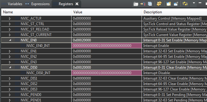
    I also noted that on my NVIC Registers, interrupt number 17 (ADC0 - SS3) is both set in NVIC_EN0 and NVIC_DIS0, which means the interrupt is both enabled and disabled and the same time? The changes happen after IntEnable(INT_ADC0SS3);

    Might it be the cause of the interrupt never occuring besides forced?

  • Many should like the effort you've expended and the clarity of this last post - well done.

    Your use of the "forced trigger" was quite clever - and points to a (likely) "solution path" for you. Via the MCU manual's "list of ADC Registers" you may systematically examine the (appropriate) ADC Registers which "reflect or govern" ADC interrupts. Then do the same for the "list of Interrupt Registers." You are seeking (any) "interrupt bit" differences between the "forced trigger" and your "normal code."

    Know that (both) poster Robert & I want "you" to "drive your issue to solution!"     Might your (detailed) examination of the source code w/in "IntTrigger()" provide insight?   (especially useful - as that function (alone) - thus far - has worked!)

    As a (sometimes) proponent of KISS here - I'd prefer you to "unhook" your ADC interrupt from any timer - use the "Processor Trigger" as a simpler and more direct trigger.   (i.e. remove the possibility - however slight - for the Timer to "Hold your ADC Interrupt hostage!"    i.e. exploit one of the key benefits of the (banned here) KISS!)

    I recall that some ADC Registers are "sensitive" to "reads" - and if "open" in your IDE - that may cause flawed MCU response. The MCU manual's presentation of the Registers (usually) identifies such "sensitive" registers - be sure to check to see if (that) describes your condition...

    You may also "change the order" of "IntEnable() and ADCIntEnable()." (pure "swag" - yet (any) port during a storm) Do check that the parameters for both of these functions are proper. (there have been so many revisions of xWare - checking beats hope)

  • Thanks for the reply...

    So I've changed the trigger source for the ADC to Processor and tried to initiate using ADCProcessorTrigger... nothing happened. I also tried to use TRIGGER_ALWAYS and... nothing happened.

    Looking in the register map, everything has the same values between using IntTrigger or not, apart from the expected changes. But, when I halt execution in the while(1) loop, ADCBusy is 1, always. So that means it is converting?

    One thing came into my mind: If I use timer interrupt, and inside its ISR call IntTrigger for the ADC, will it work? I mean, with appropriate priorities and settings, it would, but timing will be affected, right?
  • 	// Configure Step 0 of Sequencer 3
    	ADCSequenceStepConfigure(ADC0_BASE, 3, 0, (ADC_CTL_IE | ADC_CTL_END | ADC_CTL_SHOLD_8 | ADC_CTL_CH8));
    

    Where does ADC_CTL_SHOLD_8 come from? I can't find it in the TIVAWare manuals I've looked at or the header files (although I'm using an older version).

    Robert

  • Robert Adsett72 said:
    Where does ADC_CTL_SHOLD_8 come from? I can't find it in the TIVAWare manuals I've looked at or the header files (although I'm using an older version).

    It's for the ADC hold the sample for 8 clock cycles. Defined in driverlib/adc.h of TivaWare 2.1.4.178

  • Luiz Felipe K Evaristo said:
    Robert Adsett72
    Where does ADC_CTL_SHOLD_8 come from? I can't find it in the TIVAWare manuals I've looked at or the header files (although I'm using an older version).

    It's for the ADC hold the sample for 8 clock cycles. Defined in driverlib/adc.h of TivaWare 2.1.4.178

    What is it defined as?

    Robert

  • //*****************************************************************************
    //
    // Values that can be passed to ADCSequenceStepConfigure as the ui32Config
    // parameter.
    //
    //*****************************************************************************
    #define ADC_CTL_TS              0x00000080  // Temperature sensor select
    #define ADC_CTL_IE              0x00000040  // Interrupt enable
    #define ADC_CTL_END             0x00000020  // Sequence end select
    #define ADC_CTL_D               0x00000010  // Differential select
    #define ADC_CTL_CH0             0x00000000  // Input channel 0
    #define ADC_CTL_CH1             0x00000001  // Input channel 1
    #define ADC_CTL_CH2             0x00000002  // Input channel 2
    #define ADC_CTL_CH3             0x00000003  // Input channel 3
    #define ADC_CTL_CH4             0x00000004  // Input channel 4
    #define ADC_CTL_CH5             0x00000005  // Input channel 5
    #define ADC_CTL_CH6             0x00000006  // Input channel 6
    #define ADC_CTL_CH7             0x00000007  // Input channel 7
    #define ADC_CTL_CH8             0x00000008  // Input channel 8
    #define ADC_CTL_CH9             0x00000009  // Input channel 9
    #define ADC_CTL_CH10            0x0000000A  // Input channel 10
    #define ADC_CTL_CH11            0x0000000B  // Input channel 11
    #define ADC_CTL_CH12            0x0000000C  // Input channel 12
    #define ADC_CTL_CH13            0x0000000D  // Input channel 13
    #define ADC_CTL_CH14            0x0000000E  // Input channel 14
    #define ADC_CTL_CH15            0x0000000F  // Input channel 15
    #define ADC_CTL_CH16            0x00000100  // Input channel 16
    #define ADC_CTL_CH17            0x00000101  // Input channel 17
    #define ADC_CTL_CH18            0x00000102  // Input channel 18
    #define ADC_CTL_CH19            0x00000103  // Input channel 19
    #define ADC_CTL_CH20            0x00000104  // Input channel 20
    #define ADC_CTL_CH21            0x00000105  // Input channel 21
    #define ADC_CTL_CH22            0x00000106  // Input channel 22
    #define ADC_CTL_CH23            0x00000107  // Input channel 23
    #define ADC_CTL_CMP0            0x00080000  // Select Comparator 0
    #define ADC_CTL_CMP1            0x00090000  // Select Comparator 1
    #define ADC_CTL_CMP2            0x000A0000  // Select Comparator 2
    #define ADC_CTL_CMP3            0x000B0000  // Select Comparator 3
    #define ADC_CTL_CMP4            0x000C0000  // Select Comparator 4
    #define ADC_CTL_CMP5            0x000D0000  // Select Comparator 5
    #define ADC_CTL_CMP6            0x000E0000  // Select Comparator 6
    #define ADC_CTL_CMP7            0x000F0000  // Select Comparator 7
    #define ADC_CTL_SHOLD_4         0x00000000  // Sample and hold 4 ADC clocks
        #define ADC_CTL_SHOLD_8         0x00200000  // Sample and hold 8 ADC clocks
    #define ADC_CTL_SHOLD_16        0x00400000  // Sample and hold 16 ADC clocks
    #define ADC_CTL_SHOLD_32        0x00600000  // Sample and hold 32 ADC clocks
    #define ADC_CTL_SHOLD_64        0x00800000  // Sample and hold 64 ADC clocks
    #define ADC_CTL_SHOLD_128       0x00A00000  // Sample and hold 128 ADC clocks
    #define ADC_CTL_SHOLD_256       0x00C00000  // Sample and hold 256 ADC clocks

    from the file

  • Two thoughts,
    - You should probably clear interrupts before enabling them
    - You need to determine (re-determine?) that you've got the correct interrupt hooked up. If a differnt interrupt fires do you have default handlers and if so can you tell if they are called?

    Robert
  • Friend Robert makes usual "good/critical" points.    

    If I may - an even more BRUTAL (KISS influenced approach - of course) would see you (temporarily) halt all other interrupts - even the bulk of "Non ADC related code" - so that, "NO Outside intrusions are able to "spoil your attempt to achieve the ADC Interrupt."     

    I would also suggest that you (again temporarily) load the vendor example/peripheral code, "Single_Ended.C" - changing ONLY the ADC code listing to your ADC0_SS3.    

    We need to get (something) to work - KISS stresses the fundamentals - the basics - kicking these to the curb leads to the "pain/suffering" you/Robert/and I are (now) enduring.   DO try Single-Ended.C with ONLY the change to SS3.   (none other, please - MORE is NOT the way to proceed!)

  • Agreed starting from the known good example and slowly changing to the desired goal would be a worthy process.

    Robert
  • Surely as it is a "Well Known" (some would even say, "LIKED" process) fully resident under KISS.

    Endless "pain/suffering" results from the "Rejection of KISS!"

  • cb1_mobile said:

    I would also suggest that you (again temporarily) load the vendor example/peripheral code, "Single_Ended.C" - changing ONLY the ADC code listing to your ADC0_SS3.    

    so I've used this code, exactly as it was provided, and then changing to ADC0_SS3:

    #include <stdbool.h>
    #include <stdint.h>
    #include "inc/hw_memmap.h"
    #include "driverlib/adc.h"
    #include "driverlib/gpio.h"
    #include "driverlib/pin_map.h"
    #include "driverlib/sysctl.h"
    #include "driverlib/uart.h"
    #include "utils/uartstdio.h"
    
    void
    InitConsole(void)
    {
        //
        // Enable GPIO port A which is used for UART0 pins.
        // TODO: change this to whichever GPIO port you are using.
        //
        SysCtlPeripheralEnable(SYSCTL_PERIPH_GPIOA);
    
        //
        // Configure the pin muxing for UART0 functions on port A0 and A1.
        // This step is not necessary if your part does not support pin muxing.
        // TODO: change this to select the port/pin you are using.
        //
        GPIOPinConfigure(GPIO_PA0_U0RX);
        GPIOPinConfigure(GPIO_PA1_U0TX);
    
        //
        // Enable UART0 so that we can configure the clock.
        //
        SysCtlPeripheralEnable(SYSCTL_PERIPH_UART0);
    
        //
        // Use the internal 16MHz oscillator as the UART clock source.
        //
        UARTClockSourceSet(UART0_BASE, UART_CLOCK_PIOSC);
    
        //
        // Select the alternate (UART) function for these pins.
        // TODO: change this to select the port/pin you are using.
        //
        GPIOPinTypeUART(GPIO_PORTA_BASE, GPIO_PIN_0 | GPIO_PIN_1);
    
        //
        // Initialize the UART for console I/O.
        //
        UARTStdioConfig(0, 115200, 16000000);
    }
    
    //*****************************************************************************
    //
    // Configure ADC0 for a single-ended input and a single sample.  Once the
    // sample is ready, an interrupt flag will be set.  Using a polling method,
    // the data will be read then displayed on the console via UART0.
    //
    //*****************************************************************************
    int
    main(void)
    {
    #if defined(TARGET_IS_TM4C129_RA0) ||                                         \
        defined(TARGET_IS_TM4C129_RA1) ||                                         \
        defined(TARGET_IS_TM4C129_RA2)
        uint32_t ui32SysClock;
    #endif
    
        //
        // This array is used for storing the data read from the ADC FIFO. It
        // must be as large as the FIFO for the sequencer in use.  This example
        // uses sequence 3 which has a FIFO depth of 1.  If another sequence
        // was used with a deeper FIFO, then the array size must be changed.
        //
        uint32_t pui32ADC0Value[1];
    
        //
        // Set the clocking to run at 20 MHz (200 MHz / 10) using the PLL.  When
        // using the ADC, you must either use the PLL or supply a 16 MHz clock
        // source.
        // TODO: The SYSCTL_XTAL_ value must be changed to match the value of the
        // crystal on your board.
        //
    #if defined(TARGET_IS_TM4C129_RA0) ||                                         \
        defined(TARGET_IS_TM4C129_RA1) ||                                         \
        defined(TARGET_IS_TM4C129_RA2)
        ui32SysClock = SysCtlClockFreqSet((SYSCTL_XTAL_25MHZ |
                                           SYSCTL_OSC_MAIN |
                                           SYSCTL_USE_PLL |
                                           SYSCTL_CFG_VCO_480), 20000000);
    #else
        SysCtlClockSet(SYSCTL_SYSDIV_10 | SYSCTL_USE_PLL | SYSCTL_OSC_MAIN |
                       SYSCTL_XTAL_16MHZ);
    #endif
    
        //
        // Set up the serial console to use for displaying messages.  This is
        // just for this example program and is not needed for ADC operation.
        //
        InitConsole();
    
        //
        // Display the setup on the console.
        //
        UARTprintf("ADC ->\n");
        UARTprintf("  Type: Single Ended\n");
        UARTprintf("  Samples: One\n");
        UARTprintf("  Update Rate: 250ms\n");
        UARTprintf("  Input Pin: AIN0/PE3\n\n");
    
        //
        // The ADC0 peripheral must be enabled for use.
        //
        SysCtlPeripheralEnable(SYSCTL_PERIPH_ADC0);
    
        //
        // For this example ADC0 is used with AIN0 on port E7.
        // The actual port and pins used may be different on your part, consult
        // the data sheet for more information.  GPIO port E needs to be enabled
        // so these pins can be used.
        // TODO: change this to whichever GPIO port you are using.
        //
        SysCtlPeripheralEnable(SYSCTL_PERIPH_GPIOE);
    
        //
        // Select the analog ADC function for these pins.
        // Consult the data sheet to see which functions are allocated per pin.
        // TODO: change this to select the port/pin you are using.
        //
        GPIOPinTypeADC(GPIO_PORTE_BASE, GPIO_PIN_3);
    
        //
        // Enable sample sequence 3 with a processor signal trigger.  Sequence 3
        // will do a single sample when the processor sends a signal to start the
        // conversion.  Each ADC module has 4 programmable sequences, sequence 0
        // to sequence 3.  This example is arbitrarily using sequence 3.
        //
        ADCSequenceConfigure(ADC0_BASE, 3, ADC_TRIGGER_PROCESSOR, 0);
    
        //
        // Configure step 0 on sequence 3.  Sample channel 0 (ADC_CTL_CH0) in
        // single-ended mode (default) and configure the interrupt flag
        // (ADC_CTL_IE) to be set when the sample is done.  Tell the ADC logic
        // that this is the last conversion on sequence 3 (ADC_CTL_END).  Sequence
        // 3 has only one programmable step.  Sequence 1 and 2 have 4 steps, and
        // sequence 0 has 8 programmable steps.  Since we are only doing a single
        // conversion using sequence 3 we will only configure step 0.  For more
        // information on the ADC sequences and steps, reference the datasheet.
        //
        ADCSequenceStepConfigure(ADC0_BASE, 3, 0, ADC_CTL_CH0 | ADC_CTL_IE |
                                 ADC_CTL_END);
    
        //
        // Since sample sequence 3 is now configured, it must be enabled.
        //
        ADCSequenceEnable(ADC0_BASE, 3);
    
        //
        // Clear the interrupt status flag.  This is done to make sure the
        // interrupt flag is cleared before we sample.
        //
        ADCIntClear(ADC0_BASE, 3);
    
        //
        // Sample AIN0 forever.  Display the value on the console.
        //
        while(1)
        {
            //
            // Trigger the ADC conversion.
            //
            ADCProcessorTrigger(ADC0_BASE, 3);
    
            //
            // Wait for conversion to be completed.
            //
            while(!ADCIntStatus(ADC0_BASE, 3, false))
            {
            }
    
            //
            // Clear the ADC interrupt flag.
            //
            ADCIntClear(ADC0_BASE, 3);
    
            //
            // Read ADC Value.
            //
            ADCSequenceDataGet(ADC0_BASE, 3, pui32ADC0Value);
    
            //
            // Display the AIN0 (PE3) digital value on the console.
            //
            UARTprintf("AIN0 = %4d\r", pui32ADC0Value[0]);
    
            //
            // This function provides a means of generating a constant length
            // delay.  The function delay (in cycles) = 3 * parameter.  Delay
            // 250ms arbitrarily.
            //
    #if defined(TARGET_IS_TM4C129_RA0) ||                                         \
        defined(TARGET_IS_TM4C129_RA1) ||                                         \
        defined(TARGET_IS_TM4C129_RA2)
            SysCtlDelay(ui32SysClock / 12);
    #else
            SysCtlDelay(SysCtlClockGet() / 12);
    #endif
        }
    }
    

    I got nothing in both cases.

    As Robert said, I've tried to disable the interrupts before setting them.. got nothing, and as you said, I've let only the ADC interrupt set.. got nothing as well.

    However, I've done another test: if I call IntPendSet(INT_ADC0SS3), the program does enter the ISR. So, as it looks, the problem is on pending the ADC0 interrupt maybe?

  • Luiz Felipe K Evaristo said:
    I got nothing in both cases.

    You got nothing with the straight unmodified example program? Also what does "got nothing" mean?

    Robert

  • Does the sample (example) code provide an "ADC ISR?" If not - how valid is your report of "got nothing."

    Should you not be able to "note" the occurrence of an ADC Interrupt via (certain) ADC Register "bit readings?"
  • Looking at your code - it appears that NONE/ZERO of the "required" (multiple) Interrupt Enables have been placed w/in "Single_Ended.C"
    In addition - as noted earlier - you'd have to add the ADC ISR - to confirm its entry. (presence is required ... for entry - is it not?)

    Also - your providing a mid-level input signal (~1.65V) to the specified ADC input pin - and then "monitoring the conversion's result" - would provide (more) useful data.   It is NOT required that the ADC "interrupt" for a conversion to proceed & succeed.   Kindly provide such an input voltage level (1.65V) and report the result of your conversions.

    I believe your "end of conversion delay" to be far too small.    Increase it by a factor of 1000 - so that repeated conversions are made (somewhat) human readable...

  • cb1_mobile said:
    Looking at your code - it appears that NONE/ZERO of the "required" (multiple) Interrupt Enables have been placed w/in "Single_Ended.C"
    In addition - as noted earlier - you'd have to add the ADC ISR - to confirm its entry. (presence is required ... for entry - is it not?)

    Let's get the polled version working before worrying about interrupts.

    Robert

  • As far as I understood, the Single_ended.c works by polling the ADC, as Robert said, and I didn't change one thing in the first moment. I tried to change the Clock Source, and the ADC Pin only, as the provided code is already configured to work with Sample Sequencer 3. (In the ADC input I have put a potentiometer in which I can vary the voltage from 0 to 3.3V. )

    Supposedly, this program sends the conversion result by UART to the console for reading. Thing is, on debug mode it got stuck in while(!ADCIntStatus(ADC0_BASE, 3, false)) and the console stays blank as a result...

  • Do recall poster's report of, "Got nothing" (very much kin to "Does not Work!") likely targeted his "failure to detect" code's entry w/in ADC ISR - which requires (some) ISR presence - for such detection... This is why I suggested that he provide a known, mid range input to the ADC - so that at least the ADC's functionality could be monitored - possibly confirmed...
  • Luiz Felipe K Evaristo said:

    As far as I understood, the Single_ended.c works by polling the ADC, as Robert said, and I didn't change one thing in the first moment. I tried to change the Clock Source, and the ADC Pin only, as the provided code is already configured to work with Sample Sequencer 3. (In the ADC input I have put a potentiometer in which I can vary the voltage from 0 to 3.3V. )

    Supposedly, this program sends the conversion result by UART to the console for reading. Thing is, on debug mode it got stuck in while(!ADCIntStatus(ADC0_BASE, 3, false)) and the console stays blank as a result...

    It's not clear, do you mean it gets stuck here with the unmodified code?

    If so, try a different board. If not go back to the unmodified code and see what the behaviour is.

    Robert

  • cb1_mobile said:
    Do recall poster's report of, "Got nothing" (very much kin to "Does not Work!") likely targeted his "failure to detect" code's entry w/in ADC ISR

    I didn't see any indication that the poster was using an ISR, thus the call for amplification. It does look as as if the poster does intend this test to be polling only but I'm not yet clear on whether the unmodified code fails.

    Robert

  • Might it be that, "Got nothing" ... "conveys nothing?"
  • really sorry if I wasn't clear enough.

    I've just done this: I took the Single-Ended.c from TivaWare, put it in a new project, with all includes and etc., and tried to run it on the board. As a result, I get a blank console where should be ADC readings, and if I pause the debug, it indicates that the code is inside while(!ADCIntStatus(ADC0_BASE, 3, false)), and don't get out of it. I don't have other boards at the moment.

    The strange thing is, analyzing the code, it looks like the processor triggers ADC conversion, and it waits for a clear in the interrupt flag, which isn't set as no interrupts are set. Confusing, to say the least. This polling method doesn't seem to be configured right

  • Luiz Felipe K Evaristo said:

    really sorry if I wasn't clear enough.

    I've just done this: I took the Single-Ended.c from TivaWare, put it in a new project, with all includes and etc., and tried to run it on the board. As a result, I get a blank console where should be ADC readings, and if I pause the debug, it indicates that the code is inside while(!ADCIntStatus(ADC0_BASE, 3, false)), and don't get out of it. I don't have other boards at the moment.

    OK. We need someone with '129 experience to verify that this does work on a '129 but AFAIK this is known good working code. You really need to get another board, as cb1 might say "Ware the single board anomaly".  BTW is this your own board or an eval board such as a Launchpad you're working with?

    Getting another Launchpad to test with should be a rapid and easy process.

    Luiz Felipe K Evaristo said:
    The strange thing is, analyzing the code, it looks like the processor triggers ADC conversion, and it waits for a clear in the interrupt flag, which isn't set as no interrupts are set. Confusing, to say the least. This polling method doesn't seem to be configured right

    Others have run this code w/o modification. It should be good code but may be worth having someone with direct '129 experience verify that it is.

    Robert

  • Crack staff & this humble reporter can (and do) confirm that "single_ended.c" works on (both) LX4F231 & 4C123! (no 129's allowed - our building...)
    As the day completes we will try to work in an (added) ADC Interrupt (and enabling code) - and see if the interrupt (finally) is triggered...

    Luiz - we will not "abandon" you - we both appreciate your effort - it is a good learning exercise for all of us - do keep "trying" and NOT to get discouraged...

  • thanks, I will ask for a colleague's board. It is the TM4C CryptoConnected Launchpad.

    I will report if any of the codes works on another kit
  • Hello Luiz,

    Can you attach the CCS project you created for the TivaWare provided single-ended example? I will download and test it on my own hardware as well.
  • I have asked for two friends who have the board, and they reported the same issues I had, code stuck at that instruction I mentioned above.

    Here is the project:

    adc_single_ended_test.rar

  • May I note that my firm (just) ran, "Single_Ended.C" without ISSUE!     (as included under StellarisWare, Ver 9453)    (only version of vendorWare "approved" by firm's key clients - due to its robustness/stability & uniquely broad MCU coverage!)   

    Tests were run on (both) LX4F231 (we've employed thousands) and TM4C123 - both proved successful - "NO HANGS" were encountered.     (we remain "unimpressed" w/ 120MHz 129 - have NONE - thus could not include...) 

    If useful - I will provide that (past) example code file for review.    (such may explain our (and our key clients) "hesitation/reluctance" to switch to newer vendorWare incarnations!)    Note that StellarisWare 9453 is the sole vendor offering which supports: LM3S, LX4F and TM4C123 (123 via/very slight mod: {pinmap.h})     Firm actively (still) supports those (past - predecessor LMI & this vendor's) MCUs...

  • thanks for the feedback. I would like to know, did the console show the setting messages and then the ADC conversion values? Because I didn't even get the configuration messages (forgot to mention that earlier).

    I would switch to TM4C123 as it has much more support and technical data, but I don't have much time...

  • Hello Luiz,

    Thank you for sharing your CCS Project. I didn't have a Crypto LaunchPad handy so I used the EK-TM4C1294XL LaunchPad instead. With the example you provided, the clock settings were not right as the LaunchPad (both 1294XL and 129EXL) has a 25MHz crystal, not a 16MHz crystal.

    Once I fixed the clock settings, the example ran for me with no issues including getting full UART output.

    The clock settings I used are:

        SysCtlClockFreqSet((SYSCTL_XTAL_25MHZ |
                            SYSCTL_OSC_MAIN |
                            SYSCTL_USE_PLL |
                            SYSCTL_CFG_VCO_480), 120000000);

    Please try this and see if we can get you back to the baseline of the single_ended example running properly.

  • Also forgot to note but make sure to use the UART settings of 8n1 115200 bps for your terminal software, connected to COM port for the ICDI ("Stellaris Virtual Serial Port")
  • Ralph Jacobi said:

    ... UART settings of 8n1 115200 bps for your terminal software, connected to COM port for the ICDI ("Stellaris Virtual Serial Port")

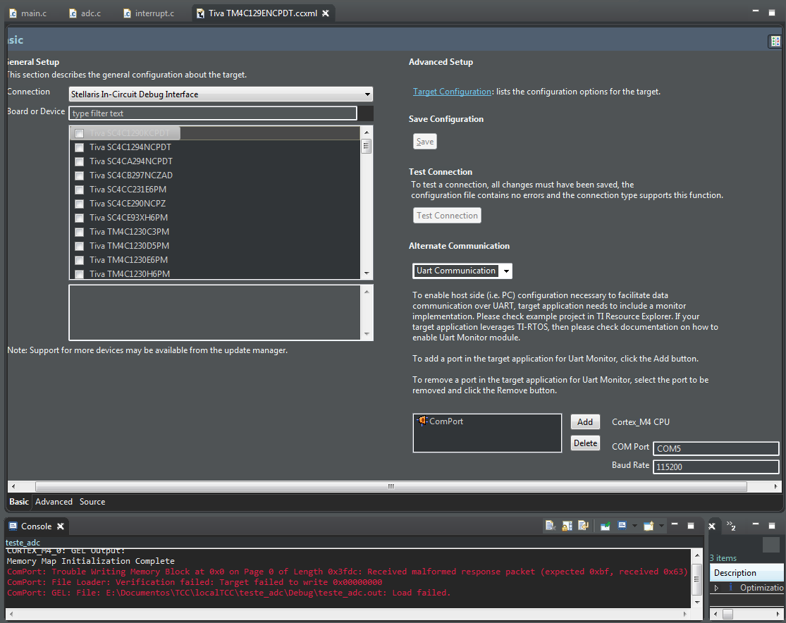
    I've done some research about setting COM ports, and so I configured. However, if I set a COM port with baud 115200, I get this error:

    If I remove the ComPort, the program loads normally, although still don't working as it should. I'm probably doing something wrong, but I'm not sure what it is...

  • Hello Luiz,

    Sorry for any confusion I may have caused but the UART settings I referred to were for terminal programs like PuTTY or Docklight to receive the UART data when the application is running. Not the CCS Configuration file. I just mentioned the IDCI port because there are 2 USB ports plugs on the Tiva LaunchPad so I wanted to make sure you had correct port selected for the UART terminal software as you reported getting zero messages from it before.

    Use the CCS .ccxml settings as they are by default.

    For PuTTY/Docklight/TeraTerm etc. - use the settings I listed to see the output of the UART functions in the TM4C single_ended.c example.

    Hopefully that is more clear now. :)
  • Thanks Ralph!

    Using Hercules Terminal I was finally able to see the ADC conversion values, as it was intended. So polling method does work, but why not the interrupt method now?

    Thanks again

  • Luiz Felipe K Evaristo said:
    So polling method does work, but why not the interrupt method now?

    It is assumed that you've followed the suggestion to employ, "Single_Ended.C" - that (is) the case - is it not?     That example program does not provide an Interrupt Service Routine - iirc.

    Little should prevent you from adding a short ISR (preferred is placement w/in your start-up file) - and then observing its entry.

  • Luiz Felipe K Evaristo said:
    Using Hercules Terminal I was finally able to see the ADC conversion values, as it was intended. So polling method does work, but why not the interrupt method now?

    Now, you've two paths forward. You could add interrupts to this program or you could change to a different sequencer. Don't, however, do both at once.

    The basic idea is to add pieces one by one until either you reach the point where it fails to work or you have all the features present. In the former case you will have a relatively small set of changes to look at as being problematic.

    Robert

  • May it be noted that Robert's "incrementalism" may be described by the (likely) better known/more memorable, "KISS!"

    Much to be said for simplicity - minimizing the number of "unknowns or variables" - and creating realizable and, "measurable outcomes!"     (the clear "essence" of KISS...)