This thread has been locked.

If you have a related question, please click the "Ask a related question" button in the top right corner. The newly created question will be automatically linked to this question.

TM4C129DNCPDT: system clock value isn't meet register. It might be Errata SYSCTL#22

Part Number: TM4C129DNCPDT
Other Parts Discussed in Thread: TM4C1294NCPDT, TPS22969

Hi Champs,

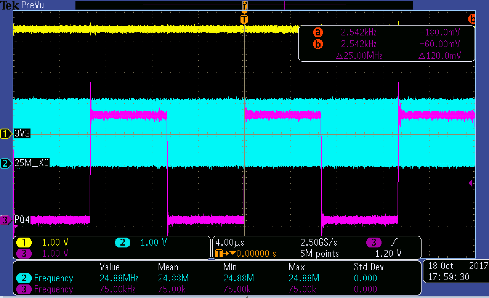
My customer set up a test procedure which power on/off M4. Power up cycle is 1s. They configure PQ4 as DIVSCLK output. They monitor the PQ4 clock. Normally, PQ4 clock will be 1.2Mhz because sysclk is 120Mhz and DIVSCLK = 99


Customer test procedure is shown below.

1. Using Arduino to do shutdown test

2. When Tm4c129DNCPDT V_3V3 rising, Arduino start to count 65ms

3. After 65ms, Arduino detect an GPIO which is assigned by FW, if the GPIO still in LOW 

state, Arduino will keep V_3V3 to wait for debug. 

-> Because if sysclk is 120Mhz, GPIO will be pull high before 65ms. If GPIO is still low after 65ms, it means sysclk be changed

4.  If GPIO in HIGH state, Arduino will shut-down the V_3V3 and do the Step 2~ Step 3 at a period 1sec again until issue happen.

5. GPIO PQ4 is used to detect the internal system clock

.

when issue happened, frequency of PQ4 is 75kHz which means sysclk is 7.5Mhz. Fvco=240, 7.5Mhz= 240/32. Looks like PSYSDIV =32. I connected ICDI to check internal SYSCTL_RSCLKCFG & STSCLT_PLLFREQ0/Q1. The setting is shown below. However, PSYSDIV is 0x1. I also check XTAL which still generate 25Mhz clock.


Another thing is that when I rewrite PSYDIV = 2 and PQ4 output frequency become 0.6Mhz. then I rewrote PSYDIV=1, PQ4 clock frequency become 1.2Mhz. It looks like system didn’t load correct value into PSYDIV. When we check errata, we found out that sysctl#22 which mentioned PSYDIV value may not be loaded into the physical divider causing the system clock to be divided by 2.


We thought will this related with this errata. Could you please help on this ? thanks !


Customer also want to know what is the difference between TM4C1294NCPDT and TM4C129DNCPDT. They faced sysclk issue before on TM4C129DNCDPT and they try to duplicate issue on Launchpad which use TM4C1294NCPDT. They can’t duplicate issue, however, issue happened when they change IC to TM4C129DNCPDT. Thanks!

Register setting

PQ4 output waveform


  • Which version of the function SysCtlClockFreqSet() are they using?
  • The difference is the addition of the security hardware accelerator on the TM4C129DNCPDT.

  • Hi Bob,

    they used latest Tiveware version is 2.1.4.178. I am not sure this issue is related with driver library or hardware. This issue is random and I spent 4 hr to duplicate the issue. Customer did stress test which power on/off TM4C129D. Could you please check the issue ? thanks!   

  • Hi Lisa,

    Lisa Ding said:
    They faced sysclk issue before on TM4C129DNCDPT and they try to duplicate issue on Launchpad which use TM4C1294NCPDT. They can’t duplicate issue,

    Might it be that after applying errata #22 work around the issue is not with PHYSDIV? Perhaps the power up reset timing or other power bus issue is causing the MCU to abort the MOSC program of PHYSDIV?

    It would seem more likely that some kind of hardware issue exists on the custom PCB that the launch pad overcomes. Several things can effect MCU performance such as reflow temperature being excessive or otherwise not consistent with documented ramp soak profiles, relative humidity of MCU prior to reflow and so many other things it is hard to pinpoint any single one being the exact cause. Process of elimination is the only way for customer to uncover what is different between the launch pad and the custom PCB.

    I would suggest the customer start by comparing VDD power up rise times (MCU reset) and 3v3 LDO to insure they are similar or better than the launch pad.

  • Hi BP101,

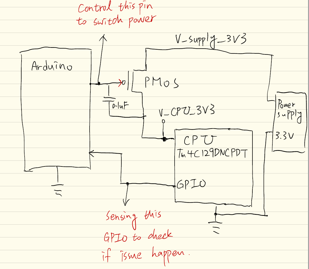
    Thanks for your reply. We duplicate this issue on TM4C129 connected launchPad actually. Customer add PMOS on 3.3v and use GPIO to control PMOS on/off. They change TM4C1294NCPDT to TM4C129DNCPDT. They also provide 3.3v waveform to me. Please see below diagram. 

    BP101 said:
    Might it be that after applying errata #22 work around the issue is not with PHYSDIV? Perhaps the power up reset timing or other power bus issue is causing the MCU to abort the MOSC program of PHYSDIV?

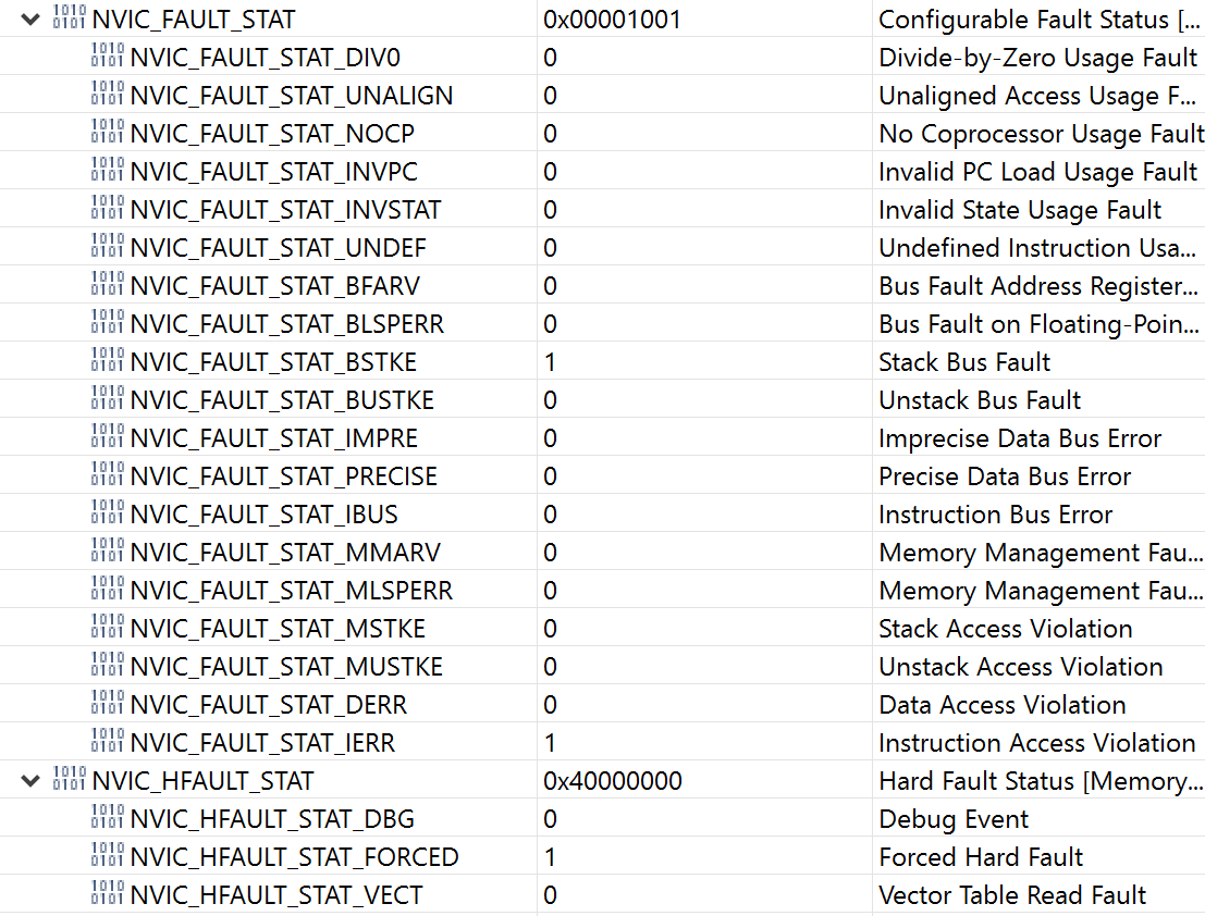
    How can we know this issue is about reset timing  or power bus issue ? How can we know MCU abort the MOSC program of PHYSDIV? Actually, this issue will trigger hard fault and customer's code is trapped in faultISR. Please see fault status register pic. thanks. 

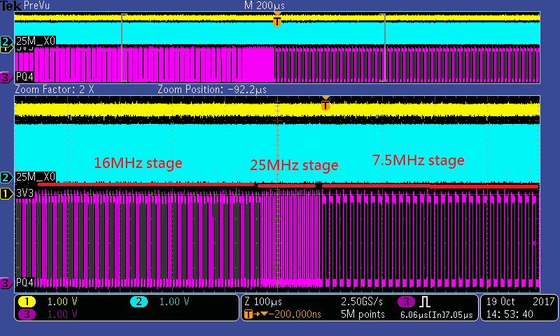
    Customer provided PQ4(DIVSCLK) waveform, the first clock resource is internal oscillator which is 16Mhz, second is 25Mhz, i guess this is external crystal frequency. customer used MOSC to be PLL input resource. Third is 7.5Mhz which is incorrect DIVSCLK. It should be 12Mhz instead. 

     DIVSCLK waveform

    3.3v waveform

    NVIC_FAULT_STAT/NVIC_HFAULT_STAT


  • Lisa Ding said:
    Thanks for your reply. We duplicate this issue on TM4C129 connected launchPad actually.

    Ok very different from earlier comment, perhaps the PMOS switch is suspect.. So the GPIO control of PMOS switch originates from Arduino pad?

    Lisa Ding said:
    How can we know this issue is about reset timing  or power bus issue ?

    The capture of reset rise time has to coincide with 3v3 power source rise time each being stable, your capture omits the reset pulse. Notice LDO turn on ripple during reset (check LDO datasheet load transient response graphs) may have some under laying connection with undesired current flow occurring from PMOS switch powering LDO and what kind of switch ? with GPIO enable pin? Is the 3v3 LDO startup capture from custom PCB or LP and do they seem to have the same startup ripple?     

    Lisa Ding said:
    How can we know MCU abort the MOSC program of PHYSDIV?

    It seems customers added circuit proved or even caused the issue and the stack is being corrupted during POR causing bus fault leading to hard fault, therefor PHYSDIV bit never gets set. A block diagram schematic of control system (load switch) would also help to clarify the GPIO control method. 

  • BP101 said:
    Ok very different from earlier comment, perhaps the PMOS switch is suspect.. So the GPIO control of PMOS switch originates from Arduino pad?

    [Lisa] Yes. They use Arduino EVM to control PMOS on/off

    BP101 said:
    what kind of switch ? with GPIO enable pin? Is the 3v3 LDO startup capture from custom PCB or LP and do they seem to have the same startup ripple? 

    [Lisa] : PMOS:

    https://www.digikey.tw/products/zh?keywords=NDT452AP

     Customer connect PMOS to 3.3v and use GPIO to connect to PMOS gate. 3.3v LDO start-up capture from Launchpad. 

    BP101 said:
    It seems customers added circuit proved or even caused the issue

    [Lisa]: Customer face this issue on their own board and duplicated the issue on launchPad.

    BP101 said:
    stack is being corrupted during POR causing bus fault leading to hard fault, therefor PHYSDIV bit never gets set.

    [Lisa]: Do you mean system trigger hardfault before set PHYSDIV part ? Customer use Tivaware bootloader example and add GPIO/sysctrl delay code. If this is stack get corrupted, it means that this is SW issues. How can we prove this is stack get corrupted and trigger bus fault? Can we use the blinky code which is easiest code. It shouldn't issue stack corrupted.  thanks

    BP101 said:
    A block diagram schematic of control system (load switch) would also help to clarify the GPIO control method. 

    [Lisa]: Please see below diagram


  • Hi Lisa,

    A combination of things might be causing the crash not to exclude complicating the primary issues by adding more hardware. First I would recommend the customer review datasheet pages 223-224 and verify analog LDO is stable when RST reset occurs in proper timing as shown in Table 27-14 figure 27-11. That was my maddening reason to suggest customer add capture of RST pin along with 3v3 power up. Perhaps even check the RESC register, check BOR set if there was a dip in LDO supply event when ever the PHYSDIV value is not being set. BTW the launch pad violates the datasheet RST pin recommendations.

    Adding a PMOS switch versus an actual load switch may not be the best method. Recommend customer review TI load switch seminar (excellent!) and look at datasheet TPS22969 or other PMOS load switches. That is if they truly want controls for their experiment, must eliminate all anomaly causing conditions from the adding of sub systems.

    Lisa Ding said:
    [Lisa]: Do you mean system trigger hardfault before set PHYSDIV part ? Customer use Tivaware boot loader example and add GPIO/sysctrl delay code. If this is stack get corrupted, it means that this is SW issues


    Ok the serial boot loader adds a whole other can of worms into the experiment since it preforms copy of flash stored application into SRAM where it executes. Very often MOSC is again configured (main()) of application, perhaps add a 1 second SYS delay after MOSC reconfigured in main. That should arrest any race conditions that might arise after the copy of Flash application into SRAM then executes.

    Perhaps it would be wise customer only focus on issue setting PHYSDIV value by entering a while(1) loop after MOSC is configured. NO other code in flash and completely erase flash memory of serial boot loader starting the PHYSDIV test application @0x0. In that way it will confirm or eliminate SW being the cause of PHYSDIV issue. 

  • Hi BP101,
    Thanks for your reply. I just wondering that if MCU abort before MOSC setting. Why clock become correct after I connect with TM4C129 and rewrite the PSYDIV value ? MCU should still in fault state after I re-wrote PSYDIV?
  • Lisa Ding said:
    Why clock become correct after I connect with TM4C129 and rewrite the PSYDIV value ?

    Not sure how you manage to rewrite the PHYSDIV bit into control register while the CPU is in a hard fault state let alone how it then reads the register without first clearing the hard fault. 

    Lisa Ding said:
    MCU should still in fault state after I re-wrote PSYDIV?

    The only why to correct a hard fault that I'm aware is to reset or POR the MCU. However the ARM cortex CPU can be forced via registers to continue running during a hard fault condition. Seemingly that becomes useful in recovering the MCU state information while in the hard fault infinite loop function.

    The best way to determine the culprit of hard fault is to eliminate as much that could impact any and all MOSC configurations. The boot loader first configures the MOSC after POR, does your application later re-configure MOSC? 

  • BP101 said:
    Not sure how you manage to rewrite the PHYSDIV bit into control register while the CPU is in a hard fault state let alone how it then reads the register without first clearing the hard fault. 

    I just use emulator then connect to TM4C129 by using CCS. I launched target configuration first then connect to target. In this step, I can access TM4C129 register and re-wrote it.

    Also, if TM4C129 exit hard fault state, I shouldn't see hard fault flag in register. However, I did see fault flag in register. that's also a weird part.  

    I checked datasheet which show MOSC Failure Reset. If MOSC didn't configure correctly, will MCU generate MOSC Failure Reset ? If it will generate reset, MCU shouldn't be trapped in fault state.

  • Lisa Ding said:
    I launched target configuration first then connect to target

    Perhaps the ICDI is resetting the Target upon connection? You can verify if the check box to reset target on connect is set in the debug properties.

    Lisa Ding said:
    In this step, I can access TM4C129 register and re-wrote it.

    And you actually see the DIVSCLK output change frequency?

    Lisa Ding said:
    Also, if TM4C129 exit hard fault state, I shouldn't see hard fault flag in register. However, I did see fault flag in register. that's also a weird part.  

    That may seem a fairly good indication the CPU was not reset on connection or the debug register continuous refresh button has not been clicked. Perhaps you see the cached results of the last debug, especially if a hard fault occurs during your current debug connection the refresh is not updating the register view.

    Lisa Ding said:
    I checked datasheet which show MOSC Failure Reset. If MOSC didn't configure correctly, will MCU generate MOSC Failure Reset ?

    The watchdog timer may reset the MCU on a fault without you being aware it occurred, especially if you have no blinking LED indicators in your application. Check the errata for your MCU it might have issue with reporting MOSC failure. That would of course infer such a failure is indeed occurring.

    Have you yet removed the boot loader from your application firmware? 

  • Hi BP1,

    BP101 said:
    Perhaps the ICDI is resetting the Target upon connection? You can verify if the check box to reset target on connect is set in the debug properties.

    I don't  think ICDI reset the device. Because I connect with TM4C129 and register setting isn't default value. It is customer's code setting.

    BP101 said:
    And you actually see the DIVSCLK output change frequency?

    Yes. I provide the waveform in my first post. When I re-write the PSYDIV, DIVSCLK freq is changed back to normal.

    In customer setting, TM4C129 won't run the whole project because customer will reset TM4C129 before bootloader executed. thanks!

    #include "inc/hw_gpio.h"
    #include "inc/hw_memmap.h"
    #include "inc/hw_sysctl.h"
    #include "inc/hw_types.h"
    #include "driverlib/sysctl.h"
    #include "driverlib/gpio.h"
    
    #define SYSTEM_DELAY_MS ( 120000/3 )
    
    
        SysCtlPeripheralEnable(SYSCTL_PERIPH_GPIOQ);
    
        GPIOPinConfigure(GPIO_PQ4_DIVSCLK);
    
        GPIOPadConfigSet(GPIO_PORTQ_BASE, GPIO_PIN_4, GPIO_STRENGTH_2MA,GPIO_PIN_TYPE_STD);
    
        GPIODirModeSet(GPIO_PORTQ_BASE, GPIO_PIN_4, GPIO_DIR_MODE_HW);
    
        SysCtlClockOutConfig(SYSCTL_CLKOUT_EN | SYSCTL_CLKOUT_SYSCLK, 100);
    
    
        SysCtlClockFreqSet((SYSCTL_XTAL_25MHZ |
             SYSCTL_OSC_MAIN |
             SYSCTL_USE_PLL |
             SYSCTL_CFG_VCO_480), PLL_FREQ);
        SysCtlDelay(10*SYSTEM_DELAY_MS); // delay 10ms
    
        SysCtlPeripheralEnable(SYSCTL_PERIPH_GPIOE);
    
        GPIOPinTypeGPIOOutput(GPIO_PORTE_BASE, GPIO_PIN_5);
        GPIOPinWrite(GPIO_PORTE_BASE, GPIO_PIN_5, GPIO_PIN_5);
    

  • Hi Lisa,

    Lisa Ding said:
    In customer setting, TM4C129 won't run the whole project because customer will reset TM4C129 before bootloader executed

    Something not right being boot loader you first describe executes after POR, that would infer every time it executes. Later post Lisa infers the (ROM) type boot loader is being executed only once.  

  • Hi BP101,
    thanks for reply. But if flash have code then TM4C129 won't execute bootloader. It should jump to main directly.
    I just wondering that why I re-connect to TM4C129 and re-write the PSYSDIV value. DIVSCLK become 1.2Mhz clock which is correct.
  • Lisa Ding said:
    thanks for reply. But if flash have code then TM4C129 won't execute boot loader. It should jump to main directly.

    That seems to differ from several earlier posts that boot loader was being loaded. We have to assume you infer (Flash) as you did not state (ROM) boot loader was being loaded and ROM only loads application after a (FULL) erase of flash,  why bring up boot loader at all?

    All posts must be very careful describing boot process in this forum being two unique versions of boot loader exist.  Also I recall comment to place a 1 second delay after MOSC not 100ms as psoted code thus shows.     

  • Can now see application has been cleaned up from what was posted a day ago. Forum reply feature will not allow page scroll back to review past comments, (Dis-Like).
  • Hi BP101,

    BP101 said:
    All posts must be very careful describing boot process in this forum being two unique versions of boot loader exist. All this time had believed you were using the flash boot loader, not ROM boot loader since you stated it was being loaded prior to the application execution in the experiment. Clearly once the application is loaded by ROM boot loader Flash memory is not being erased each POR cycle. Today you double back on several earlier posts and state boot loader is not being executed, might that confuse all helpers to your cause? Flash embedded boot loader executes after POR every time unlike ROM boot loader single time execute.

    sorry that I confuse you. Actually, customer loaded the boot_serial code. Bootloader will execute first then customer's code. thanks for correction

    BP101 said:
    It would seem your application syntax (methods) is randomly causing a CPU hard fault, not #22 errata. No #Include directives are to be placed in (main()), placed at top of C file and are not part of the executing application. Configuring GPIO port for DIVSCLK twice in the same function is a good idea? Also I recall comment to place a 1 second delay after MOSC not 100ms as psoted code thus shows.

    I asked customer to move out bootloader and they will do experiment again. Will update after we got result. thanks

  • Notice my post explaining serial boot loader (SBL) offsets was edit out few posts up. If SBL is not placed on 32k boundary LM flash can over write the address space of application or worse merge them together. Was reason why I asked to have customer remove the SBL days ago.

    Not sure why TI choose the name (serial) though it existed prior to ROM, yet both provide a serial port load of the application. You knew right away when I stated several times (flash) BL it was not the Rom BL. In my mind if someone says SBL I know from past experience as RBL did not exist but now both exist and both are serial loaders. Perhaps better TI deprecate SBL name, rename to FSBL for everyone's sanity.
  • Hi Lisa,

    Post Resolved?
  • Hi BP101,
    Customer haven't get the new launchPad so they can't do new experiment which didn't use bootloader example code. thanks
  • Hi Lisa,

    Lisa Ding said:
    Customer haven't get the new launchPad

    Not sure why customer believes to require new launch pad when a (full) erase of flash memory removes any presence of serial boot loader. 

    Customer can use LM flash programmer to both full erase and write the test application to offset 0x0000.0000 in single secession.

  • Hi BP101,
    Because customer's original Launchpad is broken. That's why they require new one.
  • Hi Lisa,

    Lisa Ding said:
    Because customer's original Launchpad is broken.

     Have at times thought mine broken yet was able to revive or unlock DAP via LM flash programmer. Do relate accidents seem to happen at the worst times.

  • Hi BP101,

    Customer removed bootloader part in test code. However, problem still existed.
  • Hi Lisa,

    Noticed customers test code relies on PIOSC during GPIO configuration then abruptly switches to MOSC and more configuration follows.

    Would it not seem prudent to first configure MOSC then GPIO and not rely on PIOSC but only until MOSC is configured?

  • Hi Lisa,


     I am not sure what could be going on. Perhaps internally we are not getting a good reset. Do you know how long the device is powered off during this test? Does the frequency of occurrence of this problem change if the device is powered off longer? From one scope picture you posted it looked like the external voltage dropped to 360mV. Will it drop lower if powered off longer?

  • Bob Crosby said:
    Do you know how long the device is powered off during this test

    [Lisa]:Power off is 935ms, Power on is 65ms. Please see below waveform

    Bob Crosby said:
    Does the frequency of occurrence of this problem change if the device is powered off longer?

    [Lisa]: Never did this. The reason why you want to increase power off time is keep power to become lower ?

    Bob Crosby said:
    Will it drop lower if powered off longer

    [Lisa]: Yes. Customer said voltage drop lower if keep power off longer.

    I checked datasheet which TM4C129 reset falling voltage is 1.84v, customer's board offset is 360mv. It should be able to generate POR.

    I'm just wondering that the clock waveform is 16Mhz -> 25Mhz -> 7.5Mhz. 16Mhz looks like internal oscillator, 25Mhz is external oscillator value. 7.5Mhz is sysclk. TM4C129 used internal osc when power on then change to external oscillator due to customer used MOSC to be PLL input source. If 16Mhz changed to 25Mhz, I think 129 already reset and ran code. I connected with 129 when issue happened. I checked register setting already be changed to customer setting and rewrote PSYSDIV to 2. clock output changed and I rewrote PSYSDIV to 1. Sysclk became 12Mhz. Looks like PSYSDIV didn't load correct number. There is a errata SYSCTL#22 which showed "This register value may not be loaded into the physical divider causing the system clock to be divided by 2." Could you please help to verify it ? thanks.  

  • Hi Lisa,

    Perhaps you might check GPIO PQ4=DIVSCLK (MPU pin 102) is disconnected from U4_OC2 output. OC2 pin 5 being held low seemingly presents a short on LDO +3v3 each time DIVSCLK signal peaks and (may) lead to a failed launch pad. Table 26-6 indicates DIVSCLK only present at PQ4 .
  • To the surrounding atmosphere,

    Tried myself to get 120Mhz DIVSCLK output on X11/Booster pack headers some time ago. Oddly the signal was an unstable awful looking square wave and Amit gave some test code for DIVSCLK made no difference in signal quality or generating the correct frequency. Had no recall at the time U4 OC2 signal was being held in a low state affecting PQ4 output.

    Suddenly realized this issue may be related recalling my application later made to monitor PQ4 report OC from GTO port,  can be DIVSCLK, MCU pin 102.